Chapter 6
High-Value
Targets
The purpose of threat doctrine is for enemy forces to locate, target, and destroy deep targets, thereby degrading friendly capabilities while adding offensive momentum to attacking enemy forces. Enemy commanders focus their most sophisticated sensors in search of HVTs. By attacking these targets, enemy forces hope to deny adequate C2, combat support, or resupply operations to forward friendly forces throughout the battlespace. Therefore, properly employing CCD at key fixed installations, such as command posts (CPs) and Army aviation sites (AASs), is essential to survival on a battlefield. HVTs fall into two general classifications-fixed installations (Section ID and relocatable units (Section IID. For information on camouflaging medical facilities, see
Avvendix F.
SECTION I - CCD PLANNING
PLANS
6-1. No single solution exists for enhancing the survivability of HVTs with CCD (except for large-area smoke screens). The characteristics of many such targets are unique and require the creative application of CCD principles and techniques. Therefore, the CCD planning process presented in this section is not intended to impose a regimen that must be followed at all costs. Rather, it suggests a logical sequence that has proven successful over time. In fact, the steps outlined below often lead to creative CCD solutions simply because they allow designers to consider the many options, benefits, and pitfalls of CCD employment. No CCD plan is wrong if it achieves the intended signature-management goals and does not impair mission accomplishment.
6-2. Each commander should develop his unit's CCD plan based on an awareness, if not a comprehensive assessment, of the detectable EM signatures emitted by HVTs under his command. He should evaluate these signatures by considering the enemy's expected RSTA capabilities (airborne and ground-based), knowledge of the target area, and weapons-on-target capability.
OBJECTIVE
techniques can best eliminate or reduce target signatures. CCD should decrease the effectiveness of enemy attacks by interfering with its target-acquisition process, which in turn increases target survivability.
PLANNING PROCESS
6-4. The steps outlined below provide guidance for designing CCD plans for HVTs. The detailed planning approach is applicable in any situation where CCD employment is necessary, but more so when the plans include HVTs.
Step 1. Identify the threat. Identify the principal threat sensors, weapon-delivery
platforms, and likely directions of attack.
Step 2. Identify critical facilities. Identify critical HVTs. Include those that are critical
from an operational standpoint and those that may provide reference points (cues) for an attack on more lucrative targets.
Step 3. Evaluate facilities. Once the critical HVTs are identified, focus efforts on
identifying the target features that might be conspicuous to an enemy RSTA.
Consider multispectral (visual, thermal, NIR, radar) signatures in this assessment. The seven recognition factors (Chavter 3) are an excellent framework for conducting this assessment. Include a review of area maps, site plans, photographs, and aerial images of the target area.
Step 4. Quantify signatures. Quantify the multispectral signatures that are emitted by
high-value facilities. Base the quantification on actual surveys of critical facilities, using facsimiles of threat sensors when possible. Specify the EM wavelengths in which targets are most vulnerable, and develop signature-management priorities.
Step 5. Establish CCD goals. Establish specific CCD goals for HVTs. These goals
should indicate the signature reduction (or increase) desired and the resources
available for CCD implementation. Base these goals on the results of steps 1 through 4. Change the CCD goals as the planning process develops and reiterate them
accordingly.
Step 6. Select materials and techniques. Select CCD materials and techniques that
best accomplish signature-management goals within logistical, maintenance, and resource constraints. Expedient, off-the-shelf materials and battlefield by-products are not identified in this manual, but they are always optional CCD materials.
Step 7. Organize the plan. Develop a CCD plan that matches goals with available
materials, time and manpower constraints, and operational considerations. If the goals are unobtainable, repeat steps 5 and 6 until a manageable plan is developed.
Step 8. Execute the plan. Once a feasible CCD plan is developed, execute it. Store
countermeasures or develop methods to defeat the CCD.
Step 9. Evaluate the CCD. The final step in the CCD planning process is to evaluate
the deployed CCD materials and techniques. Important questions to ask in this evaluation include the following:
.
Does CCD increase the survivability of HVTs?.
Does deployed CCD meet the signature-management goals outlined in the plan?.
Is deployed CCD operationally compatible with the treated target(s)?.
Are CCD materials and techniques maintainable within manpower and resource constraints?SECTION II - FIXED INSTALLATIONS
CONCEPT
6-5. Fixed installations (base camps, AASs, CPs, warehouses, roadways, pipelines, railways, and other lines-of-communication [LOC] facilities) provide scarce, nearly irreplaceable functional support to ground maneuver forces. The threat to these facilities is both ground-based and aerial. The CCD techniques for the two attack types do not necessarily change, but the defender must be aware of the overall implications of his CCD plan.
GROUND ATTACKS
6-6. Ground attacks against fixed installations (enemy offensives, terrorist attacks, and enemy special-force incursions) require constant operational awareness by the defenders. While most CCD techniques are conceptually designed to defend against an aerial attack, these same techniques can affect the target-acquisition capabilities of an enemy's ground forces to the benefit of the defender. SCSPP, LCSS, and natural vegetation provide CCD against a ground attack.
6-7. CCD discipline (light, noise, spoil) involves prudent operational procedures that friendly troops should observe in any tactical situation, particularly in the presence of hostile ground forces. (See Chavter 5 for more information.)
AERIAL ATTACKS
weapons delivery. This means attacking aircrews have limited search time once they reach the target area. Helicopters travel at slower speeds but generally encounter similar time-on-target limitations. Because of lower flying altitudes and slower speeds,
helicopters are more vulnerable to ground defenses. In either case, proper CCD can increase aircrew search time, thereby reducing available time to identify, designate, and attack an HVT. The longer an aircrew is forced to search for a target in a defended area, the more vulnerable the aircraft becomes to counterattack.
ENEMY INTELLIGENCE
6-9. The location and configuration of most fixed installations are usually well known. CCD techniques that protect against sophisticated surveillance sensor systems,
particularly satellite-based systems, can be costly in terms of manpower, materials, and time. Steps can be taken to reduce an enemy's detection of relocatable targets. Fixed installations are difficult to conceal from RSTA sensors due to the relatively long residence time of fixed installations versus relocatable targets. Unless the construction process for a given fixed installation was conducted secretly, defenders can safely assume that enemy RSTA sensors have previously detected and catalogued its location.
Defenders can further assume that attacking forces have intelligence data leading them to the general area of the fixed installation. CCD design efforts, therefore, should focus on the multispectral defeat or impairment of the enemy's local target-acquisition process.
CCD TECHNIQUES
6-10. Selected CCD techniques should capitalize on terrain features that are favorable to the defender and on the short time available to attacking aircrews for target acquisition. Use artificial and natural means to camouflage the installation. Where time and resources allow, deploy alternative targets (decoys) to draw the attention of the attacking aircrews away from the fixed installation.
6-11. Comprehensive CCD designs and techniques for fixed installations can be costly, yet field tests have shown that simple, expedient techniques can be effective. HVTs are usually supplied with artificial CCD materials. If they are not, soldiers increase the survivability of an installation by using CCD principles.
OTHER CONSIDERATIONS
6-12. While standard CCD materials are designed to enhance fixed-installation survivability, they have practical limitations that are not easily overcome. Materials applied directly to a fixed installation may achieve the signature-management goals stated in the CCD plan. However, if other features of the target scene are not treated accordingly, the target may be well hidden but remain completely vulnerable.
6-13. For example, three weapons-storage-area (WSA) igloos are in a row. The middle igloo is treated with CCD materials while the other two are not. The middle igloo will still be vulnerable. The enemy knows that three igloos exist and will probably locate the middle one no matter how well the CCD plan is designed. However, if all three igloos are treated with CCD materials and three decoy igloos are placed away from them, the
6-14. Furthermore, if a man-made object (traffic surface) or a natural feature (tree line) is close to the igloos, attacking forces will use these cues to proceed to the target area even if all three igloos are treated with CCD materials. Remember, an HVT is part of an overall target scene and an attacker must interpret the scene. Do not make his task easy. CCD plans that treat only the target and ignore other cues (man-made or natural) within the target scene are insufficient.
COMMAND POSTS
6-15. C2 systems provide military leaders with the capability to make timely decisions, communicate the decisions to subordinate units, and monitor the execution of the decisions. CPs contain vital C2 systems.
SIGNATURES
6-16. Since World War II, the size and complexity of CPs have increased dramatically. Their signatures have correspondingly increased from a physical and communications perspective (more types of antennas and transmission modes at a wider range of
frequencies). As a result, the enemy can use several conspicuous signatures to detect and target CPs for attack. Therefore, CPs require excellent CCD to survive on the battlefield.
Lines of Communication
6-17. CPs are usually located near converging LOC, such as road or rail junctions, and often require new access and egress routes. Consider the following regarding CCD and CPs:
.
Vehicle tr affic. When evaluating EM signatures that CPs emit, consider concentrations of vehicles, signs of heavy traffic (characteristic wear and track marks), and air traffic. Park vehicles and aircraft a significant distance from CPs..
Antennas. Antennas and their electronic emissions and numerous support towers are common to most CPs. Paint antennas and support equipment withnonconductive green, black, or brown paint if the surfaces are shiny. If tactically feasible, use remote antennas to reduce the vulnerability of the radio system to collateral damage.
.
Security emplacements. Security measures (barbwire, barriers, security and dismount points, and other types of emplacements) can indicate CP operations. Barbwire exhibits a measurable RCS at radar frequencies. Ensure that barbwire and concertina wire follow natural terrain lines and are concealed as much as possible.Equipment
and other thermal sources in defilade positions, within structures, or under natural cover. Heat diffusers, which tone down and vent vehicle exhaust away from threat direction, are an expedient means of thermal-signature reduction.
Defensive Positions
6-19. Defensive positions (berms, revetments, fighting positions) for protection against direct- and indirect-fire attackers typically create scarred earth signatures and detectable patterns due to earth excavation.
CCD
6-20. CCD improves OPSEC and increases survivability by minimizing the observable size and EM signatures of CPs. CP CCD requires recon, planning, discipline, security, and maintenance. Carefully controlled traffic plans decrease the possibility of disturbing natural cover and creating new, observable paths. Decoys are a highly effective means of confusing the enemy's target-acquisition process, particularly against airborne sensors. Against ground threats, the same general rules of CCD discipline apply; however, recon and heightened security patrols enhance CCD efforts against ground attack.
SITES
6-21. CP sites, which could move every 24 hours, are still occupied for a longer period than AAs. CP site selection is crucial, therefore units
should-.
Consider the needs of supporting an extended occupation while minimizing changes to natural terrain patterns. When constructing defensive positions, minimize earth scarring as much as possible. If scarred earth is unavoidable, cut vegetation, toned-down agents (paint), and camouflage nets help conceal scarred areas..
Use existing LOC (roads, trails, streams). If a site requires construction of roads or paths, make maximum use of natural concealment and existing terrain. The fewer new lines required, the better the CP blends, leaving natural features relatively unchanged..
Never locate a CP at a road junction. Road junctions are high-priority targets for enemy forces and are easily detectable..
Locate a CP in an existing civilian structure, if possible, which simplifies hiding military activity. However, choose a structure in an area where a sufficient number of buildings with similar EM signatures can mask its location.TELECOMMUNICATIONS PROCEDURES
6-22. By strictly complying with proper radio, telephone, and digital communications procedures, the opportunities for an enemy to detect friendly telecommunications activities are minimized. Consider the following:
dipoles). As a rule of thumb, place antennas a minimum of one wavelength away from surrounding structures or other antennas. NOTE: One wavelength is 40 meters (typically) for low frequencies and 1 meter for very high frequencies (VHFs).
.
Move antennas as often as possible within operational constraints..
Use directional antennas when possible. If using nondirectional antennas, employ proper terrain-masking techniques to defeat the threat's radio direction-finding efforts..
Use existing telephone lines as much as possible. Newly laid wire is a readily observable signature that can reveal a CP's location. Communications wire and cable should follow natural terrain lines and be concealed in the best way possible.CCD DISCCIPLINE
6-23. Maintain CCD discipline after occupying a site. Establish and use designated foot paths to, from, and within a CP's area. If a unit occupies a site for more than 24 hours, consider periodically rerouting foot paths to avoid detectable patterns. Conceal security and dismount points and other individual emplacements, and make paths to the CP inconspicuous. Enforce proper disposal procedures for trash and spoil. Rigidly enforce light and noise discipline. Enhance the realism of a decoy CP by making it appear operational. Allow CCD discipline to be lax in the decoy CP, thus making it a more conspicuous target than the real CP.
SUPPL Y AND WATER POINTS
6-24. Supply and water points provide logistical support-the backbone of sustained combat operations. As these targets are relatively immobile and the object of an enemy's most sophisticated sensors, using CCD is one of the most effective means to improve their survivability.
OPERATIONS
6-25. Many CCD methods associated with AAs and CPs also apply to supply and water points, but with additional requirements. Large amounts of equipment and supplies are quickly brought into tactical areas and delivered to supply points located as close to the FLOT as possible. Supplies must be unloaded and concealed quickly, while supply points remain open and accessible for distribution. Under these conditions, multiple supply points are generally easier to camouflage than single, large ones. Decoy supply and water points can also confuse a threat's targeting efforts.
CCD
layouts to conform with the local ground pattern. Creativity can playa role in this effort. The following guidance enhances concealment of these operations:
.
Avoid establishing regular (square or rectangular) perimeter shapes for an area..
Select locations where concealed access and egress routes are already established and easily controlled..
Use roads with existing overhead concealment if you need new access roads. Conceal access over short, open areas with overhead nets..
Control movement into and out of the supply area..
Mix and disperse supply-point stocks to the maximum extent possible. This not only avoids a pattern of stockpile shapes but also avoids easy destruction of one entire commodity..
Space stocks irregularly (in length and depth) to avoid recognizable patterns. Stack supplies as low as possible to avoid shadows. Dig supplies in if resources allow. In digging operations, disperse the spoil so as not to produce large piles of earth..
Cover stocks with nets and other materials that blend with background patterns and signatures. Flattops (large, horizontal CCD nets) are effective for concealing supply-point activities when resources allow their construction and when supply points are not too large. Dunnage from supply points provides excellent material for expedient decoys.TRAFFIC CONTROL
6-27. Ensure that vehicles cause minimal changes to the natural terrain as a result of movement into, within, and out of the area. Provide concealment and control of vehicles waiting to draw supplies. Rigidly practice and enforce CCD discipline and OPSEC. Debris control could be a problem and requires constant attention.
WATER POINTS
6-28. CCD for water points include the following additional considerations:
.
Spillage. Water spillage can have positive and negative effects on a unit's CCD posture. Standing pools of water reflect light that is visible to observers. Pools can also act as forward scatterers of radar waves, resulting in conspicuous black-hole returns on radar screens. Therefore, minimize water spillage and provide adequate drainage for runoff. On the other hand, dispersed water can be used to reduce the thermal signatures of large, horizontal surfaces. However, use this technique sparingly and in such a way that pools do not form.water-point equipment to eliminate shine from damp surfaces. Conceal shine by placing canvas covers on bladders, using camouflage nets, and placing foliage on and around bladders. This also distorts the normal shape of the bladders.
.
Scheduling. Enhance CCD discipline at water points by establishing and strictly enforcing a supply schedule for units. The lack of or violation of a supplyschedule produces a concentration of waiting vehicles that is difficult to conceal.
ARMY AVIATION SITES
6-29. AASs are among the most important of all battlefield HVTs. AASs are typically comprised of several parts that make up the whole, including tactical assembly areas (TAAs), aviation maintenance areas (AMAs), forward operating bases (FOBs), and forward arming and refueling points (FARPs). The positioning of AAS elements with respect to each other is dynamic and often depends on the existing tactical situation. In the following discussion, an AAS will be defined as a TAA, an AMA, and a FARP collocated in the same area. While these elements are not always collocated, the CCD techniques for individual elements will not greatly differ based on positioning. Untreated AASs are detectable in most threat sensor wavelengths.
.
TAA. A TAA is typically a parking area for helicopters. Helicopters are high!y conspicuous targets because of their awkward shape, distinctive thermalsignatures, and large RCS. An enemy expends a lot of time and energy attempting to locate TAAs. Once it finds them, the enemy aggressively directs offensive operations against them.
.
AMA. The most conspicuous features of an AMA are the large transportable maintenance shelters. These shelters are highly visible and indicate the presence of helicopters to an enemy. AMAs occupy large areas to allow for ground handling of aircraft. Traffic patterns around AMAs are also strong visual cues to the enemy. Maintenance assets, including aviation shop sets, havecharacteristically distinct multispectral cues.
.
FARP. A FARP provides POL and ammunition support to AASs and other tactical units. A FARP consists of fuel bladders, heavy expanded mobility tactical trucks (HEMTTs), fueling apparatus, and bulk ammunition. Due to safetyrequirements, FARP elements are dispersed as much as possible within terrain and operational constraints. Each element is detectable with multispectral radar. In
aFARP-. Fuel bladders contain petroleum liquids whose thermal mass is a strong IR cue relative to the background. Bladders are often bermed, which means that visible earth scarring is necessary to construct the berm.
. Large HEMTTs are conspicuousin all wavelengths.
apparatus (hoses, pumps) are arranged linearly in an open area for safe and easy access. The linear deployment of these hoses is a strong visual cue, and their dark color usually contrasts with the background. The dark hoses experience solar loading, and the POL liquids within the hoses can provide a thermal cue.
.
Equipment. Palletized ammunition and support equipment accompany AASs. Such equipment is often stacked in regular, detectable patterns..
Aircraft. Aircraft create large dust plumes when deployed to unpaved areas. Such plumes are distinct visual cues and indicate the presence of rotary aircraft to an enemy.. Parked aircraft. Camouflage nets, berms, stacked equipment, and revetments can effectively conceal parked aircraft. Vertical screens constructed from camouflage nets help conceal parked aircraft,
particularly against ground-based threats. However, CCD techniques for rapid-response aircraft must not impair operational requirements, meaning that obtrusive, permanent CCD techniques are generally not an option. Also, foreign object damage (FOD) is a critical concern for all aviation assets. CCD for parked aircraft depends on the expected ground time between flights. The commanding officer must approve all aircraft CCD techniques before implementation.
. Aircraft refueling. Aircraft refueling positions, particularly fuel hoses, should be dispersed and arrayed in a nonlinear configuration. The hoses can be concealed at periodic locations with cut vegetation or a light earth/sod covering to reduce visual and thermal signatures.
.
Defensive positions. Constructing defensive positions can create detectable areas of scarred earth..
CCD. AASs are extremely valuable targets; therefore, try to prevent their initial detection by an enemy..
Vehicles. Large vehicles can be effectively concealed with camouflage nets. Also, properly placing these vehicles to use terrain features and indigenous vegetation increases their survivability. Expedient vehicle decoys provide an enemy with alternate targets, and proper CCD discipline is essential..
Dunnage. Quickly conceal all dunnage (packing materials) to minimize the evidence of AASs..
Construction. When constructing defensive positions, minimize disturbances to the surrounding area. Cover scarred earth with cut vegetation, camouflage nets, or toned-down agents.SECTION 111- RELOCATABLE UNITS
MOBILITY AND CCD
6-30. Examples of valuable relocatable units include TOCs, tactical-missile-defense (TMD) units (Patriot batteries), refuel-on-the-move (ROM) sites, and FARPs. These units are critical to offensive and defensive operations, and their protection should receive a high priority.
6-31. Mobility and CCD enhance the survivability ofrelocatable units. A CCD plan must include the techniques for units to deploy rapidly and conduct mobile operations
continuously. The CCD techniques available to mobile units are basically the same as for fixed installations, and the principles of CCD still apply. However, the mission of
relocatable units differs from that of fixed installations so CCD execution also differs.
6-32. Relocatable units spend from a few hours to several weeks in the same location, depending on their tactical situation. CCD techniques must be planned accordingly. If a unit is at a location for a few hours, it should employ expedient CCD techniques. If a unit is at a location for several days, it should employ robust CCD plans. The resources a unit expends on CCD execution must be weighed against the length of time that it remains in the same location. As CCD plans increase in complexity, subsequent assembly and teardown times also increase. Commanders must ensure that the unit's manpower and resources dedicated to CCD execution are equal to the tactical mobility requirements.
BUILT -IN CAP ABILITIES
6-33. CCD should be built into systems to the maximum extent possible. Supplemental CCD is usually necessary and should be designed to enhance the built-in CCD. Apply the same rules for avoiding detection and the same considerations regarding the seven
Chapter 7
Special Environments
The fundamentals of CCD do not change between environments. The seven rules for avoiding detection and the seven recognition factors that are listed in Chavter 3 and the three CCD principles-preventing detection, improving survivability, and improving deception capabilities-still apply. However, the guidelines for their application change. Different environments require thoughtful, creative, and unique CCD techniques. This chapter discusses different CCD techniques that have proven effective in three special environments-desert, snow-covered areas, and urban terrain.
DESERT
7-1. The color of desert terrain varies from pink to blue, depending on the minerals in the soil and the time of the day. No color or combination of colors matches all deserts. Patches of uniform color in the desert are usually 10 times larger than those in wooded areas. These conditions have led to the development of a neutral, monotone tan as the best desert CCD paint color.
TOPOGRAPHY
7-2. Although desert terrain may appear featureless, it is not completely flat. In some ways, desert terrain resembles unplowed fields; barren, rocky areas; grasslands; and steppes.
SHADOWS
7-3. The closer a target is to the ground, the smaller its shadow; and a small shadow is easier to conceal from aerial observation. The proper draping of CCD nets will alter or disrupt the regular, sharp-edged shadows of military targets and allow target shadows to appear more like natural shadows. When supplemented by artificial materials, natural shadows cast by folds of the ground can be used for CCD purposes. The best solution to the shadow problem in desert terrain is to dig in and use overhead concealment or cover. Otherwise, park vehicles in a way that minimizes their broadside exposure to the sun.
PLACEMENT
TERRAIN MOTTLING
7-5. Use terrain mottling when the ground offers little opportunity for concealment. This technique involves scarring the earth with bulldozers, which creates darker areas on which to place equipment for better blending with the background. Ensure that the mottled areas are irregularly shaped and at least twice the size of the target you are concealing. Place the target off center in the mottled area and drape it with camouflage nets. When employing the scarring technique, dig two to three times as many scars as pieces of equipment being concealed. Doing this prevents the mere presence of mottled areas from giving away a unit's location.
MOVEMENT DISCIPLINE
7-6. Movement discipline is especially important in the desert. Desert terrain is uniform and fragile, making it easily disturbed by vehicle tracks. Vehicle movement also produces dust and diesel plumes that are easily detectable in the desert. When movement is
necessary, move along the shortest route and on the hardest ground. Shine is a
particularly acute desert problem due to the long, uninterrupted hours of sunlight. To deal with this problem, remove all reflective surfaces or cover them with burlap. Use matte CCD paint or expedient paints (see Table 3-2) to dull the gloss of a vehicle's finish. Shade optical devices (binoculars, gun sights) when using them.
NOISE SND LIGHT DISCIPLINE
7-7. Noise and light discipline is particularly important in desert terrain since sound and light can be detected at greater distances on clear desert nights. The techniques for reducing these signatures remain the same as for other environments. Be aware that thermal sensors, while not as effective during the day, have an ideal operating environment during cold desert nights. Starting all vehicle and equipment engines simultaneously is a technique that can be used to confuse enemy acoustical surveillance efforts.
SNOW -COVERED AREAS
7-8. When the main background is white, apply white paint or whitewash over the permanent CCD paint pattern. The amount of painting should be based on the percentage of snow coverage on the ground:
.
If the snow covers less than 15 percent of the background, do not change the CCD paint pattern..
If the snow cover is 15 to 85 percent, substitute white for green in the CCD paint pattern.PLACEMENT
7-9. A blanket of snow often eliminates much of the ground pattern, causing natural textures and colors to disappear. Blending under these conditions is difficult. However, snow-covered terrain is rarely completely white so use the dark features of the landscape. Place equipment in roadways, in streambeds, under trees, under bushes, in shadows, and in ground folds. Standard BDU s and personal equipment contrast with the snow
background, so use CCD to reduce these easily recognized signatures.
MOVEMENT
7-10. Concealing tracks is a major problem in snow-covered environments. Movement should follow wind-swept drift lines, which cast shadows, as much as possible. Vehicle drivers should avoid sharp turns and follow existing track marks. Wipe out short lengths of track marks by trampling them with snowshoes or by brushing them out.
THERMAL SIGNATURES
7-11. Snow-covered environments provide excellent conditions for a threat's thermal and UV sensors. Terrain masking is the best solution to counter both types of sensors. Use arctic LCSS and winter camouflage paint to provide UV blending, and use smoke to create near-whiteout conditions.
URBAN TERRAIN
7-12. Urbanization is reducing the amount of open, natural terrain throughout the world. Therefore, modern military units must be able to apply effective urban CCD. Many of the CCD techniques used in natural terrain are effective in urban areas.
PLANNING
7-13. Planning for operations in urban areas presents unique difficulties. Tactical maps do not show man-made features in enough detail to support tactical operations. Therefore, they must be supplemented with aerial photographs and local city maps. Local
government and military organizations are key sources of information that can support tactical and CCD operations. They can provide diagrams of underground facilities, large-scale city maps, and/or civil-defense or air-raid shelter locations.
SELECTING S SITE
7-15. The regular pattern of urban terrain; the diverse colors and contrast; and the large, enclosed structures offer enhanced concealment opportunities. Established, hardened road surfaces effectively mask vehicle tracks. Depending on the nature of the operation,
numerous civilian personnel and vehicles may be present and may serve as clutter. This confuses an enemy's ability to distinguish between military targets and the civilian population. Underground structures (sewers, subways) are excellent means of concealing movement and HVTs.
7-16. When augmented by artificial means, man-made structures provide symmetrical shapes that provide ready-made CCD. The CCD for fighting positions is especially important because of the reduced identification and engagement ranges (100 meters or less) typical of urban fighting. Limit or conceal movement and shine. These signatures provide the best opportunity for successful threat surveillance in urban terrain. Careful placement of equipment and fighting positions remains important to provide visual CCD and avoid detection by contrast (thermal sensors detecting personnel and equipment silhouetted against colder buildings or other large, flat surfaces).
ESTABLISHING FIGHTING POSITIONS
7-17. The fundamental CCD rule is to maintain the natural look of an area as much as possible. Buildings with large, thick walls and few narrow windows provide the best concealment. When selecting a position inside a building, soldiers
should-.
Avoid lighted areas around windows..
Stand in shadows when observing or firing weapons through windows..
Select positions with covered and concealed access and egress routes (breaches in buildings, underground systems, trenches)..
Develop decoy positions to enhance CCD operations.PLACING VEHICLES
us Units
I
Multiplied By Metric Units
Cubic feet
1
0.0283 Cubic meters
Feet
1
0.3048 Meters
Gallons 13.7854 Liters
Inches 12.54 Centimeters
Inches 10.0254 Meters
Inches 125.4001 Millimeters
Miles, statute 11.6093 Kilometers
Miles, statute
1
0.9144 Yards
Ounces 128.349 Grams
Pounds
10.454 Kilograms
Tons, short 10.9072 Tons, metric
Square feet 10.093 Square meters
Metric Units
1
Multiplied By US Units
Centimeters
1
0.3937 Inches
Cubic meters 135.3144 Cubic feet
Cubic meters 11.3079 Cubic yards
Grams 10.035 Ounces
Appendix A
Metric Conversion
Chart
This appendix complies with current Army directives which state that the metric system will be incorporated into all new publications. Table A-I is a conversion chart.
Kilograms 12.205 Pounds
Kilometers
1
0.62137 Miles, statute
Kilometers 11,093.6 Yards
Liters 10.264 Gallons
Meters 13.2808 Feet
Meters 139.37 Inches
Meters 11.0936 Yards
Millimeters
1
0.03937 Inches
Square meters 110.764 Square feet
Appendix B
Guidelines for Tactical Standing Operating Procedures
TACSOPs are critical to battlefield success. All commanders should establish
camouflage guidelines in their TACSOPs and ensure that their soldiers are familiar with them. TACSOPs provide guidelines that help reduce the time required to perform routine tasks. Commanders can achieve these ends by defining the responsibilities, identifying the expected tasks, and providing supervisors with a memory aid when planning or inspecting. TACSOPs, coupled with battle drills (Avvendix g, provide units with guidance on how to execute anticipated battlefield tasks. CCD employment is a task that should be routine for all units.
CONTENT
B-l. The following CCD considerations may be included in a unit TACSOP:
.
A review of CCD fundamentals..
Rules of unit CCD discipline..
Memory aids for supervisors, which should include an inspection checklist(Fifmre B-1) and a chart of an enemy's sensor systems with possible
countermeasures.
.
Guidelines on CCD discipline to provide uniformity among all subunits..
The different CCD postures..
Procedures for blackout, the quartering party, unit movement, and the deployment area..
Appropriate CCD postures in OPORDs for different missions.CCD Inspection Checklist 1. Command Emphasis.
a. The
commander-(1) Establishes CCD goals.
(3) Inspects frequently doe CCD deficiencies.
(4) Conducts follow-up inspection of CCD deficiencies.
(5) Integrates CCD into training exercises.
b. The
unit-(1) Intregrates CCD into its TACSOP.
(2) Follows the TACSOP.
2. Discipline.
a. The
unit-(1) Observes noise disciplene.
(2) Observes light discipline with respect to smoking, fires, and lights.
(3) Conceals highly visible equipment.
(4) Covers shiny surfaces.
(5) Keeps exposed activity to a minimum.
(6) Uses cut vegetation properly.
(7) Uses and conceals dismount points properly.
b.
Soldiers-(1 ) Wear the correct uniform.
(2) Control litter and spoil.
3. Techniques. The
unit-a. Places and disperses vehicles and equipment.
b. Disperses the CPo
c. Employs camoulfage nets (LCSS)
d. Uses (or minimizes) shadows. e. Minimizes movement.
f. Hides operations and equipment.
g. Blends operations and equipment with backgrounds.
i. Employs decoys.
j. Integrates smoke operations with unit movement.
k. Practices individual CCD
on-(1) Helmet.
(2) Face.
(3) Weapon.
(4) Other Equipment.
I. Employs CCD on fighting positions
by-(1) Eliminating or minimizing target silhouettes.
(2) Practicing spoil control.
(3) Eliminating or minimizing regular or geometric shapes and layouts.
(4) Maintaining overhead concealment.
(5) Practicing dust control.
m. Employs CCD on tactical vehicles
by-(1) Minimizing and concealing track marks.
(2) Minimizing or eliminating the shine on vehicles and equipment.
(3) Reducing or using shadows to the unit's advantage.
(4) Enploying camouflage nets (LCSS).
(5) Painting vehicles to match their surroundings.
(6) Dispersing vehicles and equipment.
(7) Concealing vehicles and supply routes.
(8) Controlling litter and spoil.
(9) Storing and concealing ammunition.
n. Employs CCD on AAs
by-(1) Facilitating mission planning for access and egress concealment.
(2) Marking guideposts for route junctions.
(4) Dispersing dismount, mess, and maintenance areas.
(5) Dispersing the CPo
(6) Maintaining CCD
by-(a) Inspecting CCD frequently.
(b) Controlling litter and garbage.
(c) Observing blackout procedures.
(7) Observing evaluation procedures
by-(a) Policing the area
(b) Covering or eliminating tracks.
(c) Preventing traffic congestion.
(d) Concealing spoil.
O. Employs CCD on the CP
by-(1) Ensuring that LOC are not converged.
(2) Dispersing vehicles.
(3) Ensuring that turn-ins are not widened through improper use.
(4) Ensuring that protective barriers follow terrain features.
(5) Concealing defensive weapons.
(6) Ensuring that existing poles are used for LOC.
(7) Digging in the CP (when in open areas).
(8) Maintaining camouflage nets (LCSS).
(9) Using civilian buildings properly
by-(a) Controlling access and egress.
(b) Observing blackout procedures.
(c ) Avoiding obvious locations.
p. Employs CCD on supply points
by-(1) Dispersing operations.
(3) Using the track plan.
(4) Providing concealed loading areas.
(5) Developing and implementing a schedule for the units being serviced.
q. Enploys CCD on water points
by-(1) Concealing access and egress routes.
(2) Ensuring that the track plan is used.
(3) Controlling spillage.
(4) Controlling shine and reflections.
(5) Developing and implementing a schedule for the units being serviced.
Figure B-l. Sample CCD checklist
COMMANDERS'RESPONSIBILITIES
B-2. Commanders must ensure that each soldier has the required quantities of serviceable BDU s and that these uniforms are properly maintained to protect their IR screening properties. Based on unit requirements, supply personnel forecast, request, and store adequate quantities of expendable CCD supplies (paint, makeup, repair kits). Commanders ensure that authorized quantities of CCD screens (LCSS) and support systems (to include repair kits and spare parts) are on hand and continually maintained in a clean, serviceable condition.
FRATRICIDE
Appendix C
Camouflage Requirements
and Procedures
This appendix provides information on the LCSS and describes how to erect it. Also included is a figure for determining the amount of modules needed to camouflage the various vehicles in the Army's inventory. This appendix also includes a sample battle drill that can be used to train soldiers.
LIGHTWEIGHT CAMOUFLAGE SCREEN SYSTEM
One Module
~~
Three Modules Four Modules
CAUTION The minimum required space between the LCSS and the objeci to be camouflagedis 2feet.
Stagger poles to disrupt straight lines.
Cover lig hts with brush. and Gov~r the windshield with a tarp.
Two Modules
Five Modules and One
Diamond
1
Lower the canvas flap to hide the shadow inside the truck.
Install stakes to hold the 51;;reen
A illr.... iI) q) ::2 q; (j) LL. 58 55 190 180 52 49 170 160 46 43 150 140 I 40 130 120 37
34 110 ,
100 30 27 90 80 24 21 70 60 1B 15 50 40 12 9 30 20 6
3 10 -v~
#1
Q:-~O I
Fest
Meters
Vehicle dimensions:
h ;= height
w;;;; width
L
=
lenglhA"" 2h + w + 5 ft B ==2h + L + 5 ft
11 1
\,
\ 'l\
,
\ \'
~., ,~
\'
\\
~\.
\ \ \ '.. '"'
~, ,., ,~"
\ \ ,I\.,
,,~
\ '.. "5~~'-=,-....
\.
"5 "~~~'...
\. ,,~
~
II.. """'~,
~
"""...~,-3 "',,- ~,
~~
~~---:...
2 ~
~
"
...
~;:-
--
...
NOTE: The number within each areaequals; the
number of modules.
...
,
.,
10 20 30 40 50 60 70 80 90 100 110 120130140150160170180
3 6 9 12 15 18 21 24 27 30 34 37 40 43 46 49 52 55
B
NOTE: This chart is normally relfablo for vehrclcs of regular configuration. Vehic1es oflrrogular configuration, such as artillery pieces or cranes, may require additional
modules.
Figure C-2. Module determination chart.
Table C-l. Vehicle dimensions
Nomenclature
I Height I Width I
Lengt
(feet) (feet) h Module
(feet) s
AVLB
~~~I
5C7 loader, scoop, 2-ton, w/o cage
1919~1
2D7 dozer, with blade
~~~I
2M106AI carrier, mortar, 107-mm
~~~I
2M109A3 howitzer, I55-mm (SP)
~~~I
3MI13A2 carrier, personnel
~19~1
2MI13A3 carrier, personnel
~19~1
2MI25AI carrier, mortar, 81-mm
~19~1
2MI49 trailer, water, 400-gal
~~~I
IMI72 trailer, low-bed, 25-ton
~~~I
2MIAI tank, with mine roller
~~~I
3MIAI(2) tank, combat, 105- and I20-mm
~~~I
3M2 fighting vehicle, infantry
~~r-;-I
2M2 TOW vehicle, improved
~19~1
2M3 fighting vehicle, cavalry
~~r-;-I
2M35A2 truck, cargo, 2-ton
1918~1
2M520 truck, cargo, 8-ton
~19~1
3M548 carrier, cargo, 6-ton
~19~1
2M54A2 truck, cargo, 5-ton
~18~1
2M553 truck, wrecker, lO-ton
~19~1
3M559 truck, fuel, 2,500-gal
~19~1
3M577Al carrier,
CP
1919~1
2M578 vehicle, recovery, light
M60A3 tank, combat, 105-mm
I
11
.l 12 .l 27 I 3
M713 truck, ambulance, -ton
~16~1
2M728 vehicle, combat engineer
~~~I
3M792 truck, ambulance, I-ton
18~~1
2M816 truck, wrecker, 5-ton
~18~1
3M880 truck, cargo, I-ton
18~~1
2M88Al vehicle, recovery, medium
~~r-;-I
3M9 vehicle, ACE
~~~I
2M920 truck, tractor, 20-ton
~~r-;-I
3M930 truck, dump, 5-ton
~18~1
2M977 truck, cargo, HEMTT
~18~1
3M978 truck, tanker, HEMTT
~18~1
3M992 ammo carrier (FAAS- V)
~~~I
3M998, HMMWV, carrier, personnel
16~~1
2MLRS
~~~I
2MT250 crane, hydraulic, 25-ton
~18~1
3RT crane, boom, 20-ton
~~~I
4NOTES:
1. See Avvendix E for a list ofLCSS national stock numbers (NSNs) and ordering information.
2. See TM 5-1080-200-13&P for more information on maintenance, erection, and characteristics of the LCSS.
CAP ABILITIES
C-2. The LCSS protects targets in four different ways.
It-.
Casts patterned shadows that break up the characteristic outlines of a target..
Traps target heat and allows it to disperse..
Simulates color and shadow patterns that are commonly found in a particular regIOn.ERECTING PROCEDURES
C-3. To erect camouflage nets
effectively-.
Keep the net structure as small as possible..
Maintain the net a minimum of 2 feet from the camouflaged target's surface. This prevents the net from assuming the same shape and thermal signature as the target it is meant to conceal..
Ensure that the lines between support poles are gently sloped so that the net blends into its background. Sloping the net over the target also minimizes sharp edges, which are more easily detectable to the human eye..
Extend the net completely to the ground to prevent creating unnatural shadows that are easily detected. This ensures that the net effectively disrupts the target's shape and actually absorbs and scatters radar energy..
Extend the net all the way around the target to ensure complete protection from enemy sensors.SUPPLEMENTAL
CAMOUFLAGEC-4. Camouflage nets are often employed in conjunction with supplemental camouflage because nets alone do not make a target invisible to a threat's multispectral sensors. Use other CCD techniques to achieve effective concealment. Cover or remove all of the target's reflective surfaces (mirrors, windshields, lights). Also ensure that the target's shadow is disrupted or disguised. Use native vegetation, because placing a target in dense foliage provides natural concealment and a smoother transition between the edges of the camouflage net and the target's background. Cover exposed edges of the net with dirt or cut vegetation to enhance the transition.
VEHICLE CAMOUFLAGE
C-5. Measure the vehicle or determine its dimensions from Table C-l. Use the following equations and Fifmre C-2 to determine the number of modules needed to camouflage a vehicle.
Equation 1: A
=
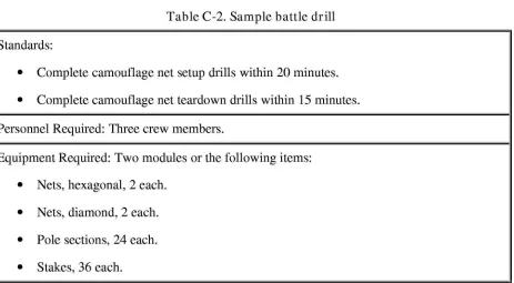
2h + w + 5 feetStandards:
.
Complete camouflage net setup drills within 20 minutes..
Complete camouflage net teardown drills within 15 minutes.Personnel Required: Three crew members.
Equipment Required: Two modules or the following items:
.
Nets, hexagonal, 2 each..
Nets, diamond, 2 each..
Pole sections, 24 each..
Stakes, 36 each.where
-h = height, in feet
w = width, in feet L = length, in feet
Step 1. Determine the vehicle's dimensions (measure or use Table C-1). For the M2
fighting vehicle, the height is 10 feet, the width is 11 feet, and the length is 22 feet.
Step 2. Use the above equations and the measurements from Step 1 to determine the
total dimensions.
A
=
2(10) + 11 + 5=
36feetB
=
2(10) + 22 + 5=
47 feetStep 3. Determine the number of modules needed (use Fifmre C-2). Since A equals
36 and B equals 47, two modules of camouflage are required to cover the M2 fighting vehicle.
TRAINING
C-6. Units should develop and practice battle drills that cover the requirements and procedures for erecting nets over assigned equipment. Table C-2 shows a sample battle drill.
.
Lanyards, 6 each..
Spreaders, 12 each.Stowage Location: The camouflage net is strapped to the right side of the trim vane.
Setup Drill:
.
The gunner and the assistant gunner remove the camouflage net from the trim vane and place it on top of the M2..
The driver removes poles and stakes from the bag and places them around the vehicle..
The gunner and the assistant gunner remove the vehicle's antenna, position the net on top of the vehicle, and roll the net off the sides of the vehicle..
The driver stakes the net around the vehicle..
The driver and the assistant gunner assemble plies and spreaders and then erect the net..
The gunner inspects the camouflage from a distance..
The crew adjusts the camouflage as necessary.Teardown Drill:
NOTES:
.
The driver and the assistant gunner take down and disassemble plies and spreaders..
The gunner and the assistant gunner unstake the net and roll it to the top of the M2..
The gunner and the assistant gunner complete rolling the net on top of the vehicle and replace the vehicle's antenna..
The driver stores the net on the trim vane..
The gunner and the assistant gunner store poles, spreaders, and stakes on the trim vane.1. Preassemble the nets before placing them on the M2.
Appendix D
Individual
Camouflage,
Concealment,
and Decoys
Each soldier is responsible for camouflaging himself, his equipment, and his position. CCD reduces the probability of an enemy placing aimed fire on a soldier.
MATERIALS
D-l. Use natural and artificial materials for CCD. Natural CCD includes defilade, grass, bushes, trees, and shadows. Artificial CCD for soldiers includes BDU s, camouflage nets, skin paint, and natural materials removed from their original positions. To be effective, artificial CCD must blend with the natural background.
DISCIPLINE
D-2. Noise, movement, and light discipline contribute to individual CCD:
.
Noise discipline muffles and eliminates sounds made by soldiers and their equipment..
Movement discipline minimizes movement within and between positions and limits movement to routes that cannot be readily observed by an enemy..
Light discipline controls the use of lights at night. Avoid open fires, do not smoke tobacco in the open, and do not walk around with a lit flashlight.DISPERSAL
D-3. Dispersal is the deliberate deployment of soldiers and equipment over a wide area. It is a key individual survival technique. Dispersal creates a smaller target mass for enemy sensors and weapons systems. Therefore, it reduces casualties and losses in the event of an attack and also makes enemy detection efforts more difficult.
CONSIDERATIONS
.
Movement. Movement draws attention, whether it involves vehicles on the road or individuals walking around positions. The naked eye, IR, and radar sensors can detect movement. Minimize movement while in the open and remember that darkness does not prevent observation by an enemy equipped with modem sensors. When movement is necessary, slow, smooth movement attracts less attention than quick, irregular movement..
Shape. Use CCD materials to break up the shapes and shadows of positions and equipment. Stay in the shadows whenever possible, especially when moving, because shadows can visually mask objects. When conducting operations close to an enemy, disguise or distort helmet and body shapes with artificial CCDmaterials because an enemy can easily recognize them at close range.
.
Shine and light. Shine can also attract attention. Pay particular attention to light reflecting from smooth or polished surfaces (mess kits, mirrors, eyeglasses, watches, windshields, starched uniforms). Plastic map cases, dust goggles worn on top of a helmet, and clear plastic garbage bags also reflect light. Cover these items or remove them from exposed areas. Vehicle headlights, taillights, and safety reflectors not only reflect light but also reflect laser energy used in weapon systems. Cover this equipment when the vehicle is not in operation.Red filters on vehicle dome lights and flashlights, while designed to protect a soldier's night vision, are extremely sensitive to detection by NVDs. A tank's red dome light, reflecting off the walls and out through the sight and vision blocks, can be seen with a starlight scope from 4 kilometers. Red-lensed flashlights and lit cigarettes and pipes are equally observable. To reduce the chances of detection, replace red filters with blue-green filters and practice strict light discipline. Use measures to prevent shine at night because moonlight and starlight can be reflected as easily as sunlight.
.
Color. The contrast of skin, uniforms, and equipment with the background helps an enemy detect OPFOR. Individual CCD should blend with the surroundings; or at a minimum, objects must not contrast with the background. Ideally, blend colors with the background or hide objects with contrasting colors.EMPLOYMENT
D-5. Study nearby terrain and vegetation before applying CCD to soldiers, equipment, or the fighting position. During recon, analyze the terrain in lieu of the CCD considerations listed above and then choose CCD materials that best blend with the area. Change CCD as required when moving from one area to another.
SKIN
doing so makes skin shiny and defeats the purpose of CCD paint. Soldiers applying CCD paint should work in pairs and help each other. Self-application may leave gaps, such as behind ears. Use the following technique:
.
Paint high, shiny areas (forehead, cheekbones, nose, ears, chin) with a dark color..
Paint low, shadow areas with a light color..
Paint exposed skin (back of neck, arms, hands) with an irregular pattern.D-7. When CCD paint sticks are unavailable, use field expedients such as burnt cork, bark, charcoal, lampblack, or mud. Mud contains bacteria, some of which is harmful and may cause disease or infection, so consider mud as the last resource for individual CCD field-expedient paint.
UNIFORMS
D-8. BDU s have a CCD pattern but often require additional CCD, especially in operations occurring very close to the enemy. Attach leaves, grass, small branches, or pieces of LCSS to uniforms and helmets. These items help distort the shape of a soldier, and they blend with the natural background. BDUs provide visual and NIR CCD. Do not starch BDU s because starching counters the IR properties of the dyes. Replace
excessively faded and worn BDU s because they lose their CCD effectiveness as they wear.
EQUIPMENT
D-9. Inspect personal equipment to ensure that shiny items are covered or removed. Take corrective action on items that rattle or make other noises when moved or worn. Soldiers assigned equipment, such as vehicles or generators, should be knowledgeable of their appropriate camouflage techniques (see Chavters 3, 1:.,and ,2:).
INDIVIDUAL FIGHTING POSITIONS
NOTE: Review the procedures for camouflaging positions in Chavter 5, which include considerations for camouflaging individual positions.
D-lO. While building a fighting position, camouflage it and carefully dispose of earth spoil. Remember that too much CCD material applied to a position can actually have a reverse effect and disclose the position to the enemy. Obtain CCD materials from a dispersed area to avoid drawing attention to the position by the stripped area around it.
D-ll. Camouflage a position as it is being built. To avoid disclosing a fighting position, never
-.
Leave shiny or light-colored objects exposed..
Remove shirts while in the open..
Leave tracks or other signs of movement.Look up when aircraft fly overhead. (One of the most obvious features on aerial photographs is the upturned faces of soldiers.)
D-12. When CCD is complete, inspect the position from an enemy's viewpoint. Check CCD periodically to see that it stays natural-looking and conceals the position. When CCD materials become ineffective, change or improve them.
Item NSN Mil No. Remar ks
Camo enamel, black 18010-00-111-8356 ~A 15gal
Camo enamel, black 18010-00-111-8005 ~A 11gal
Camo enamel, sand 18010-00-111-8336 ~A 15gal
Camo enamel, sand 18010-00-111-7988 ~A 11gal
Camo screen, ultralite,
1080-01-338-4468 ~N8811616FVU-165/G asphalt/concrete
Camo screen, ultralite, green/tan 1080-01-338-4471 ;N8 811600 FVU - 166/G
Camo screen, ultralite,
1080-01-338-4469 ~N8811617FVU-164/G snow/partial snow
Camo support set, ultralite
(A-1080-01-338-4472 ~N8811615 ~TU-96/G frame)
Connector plug, w/o gen-test 5935-01-050-6586 MS3456W1 Use 5935-00-431-4935 6S-1P
Connector, receptacle, electrical
1370-01-171-1336 293E663P4 l.4G class/div, 49 ea
CCK-77/E 04
Appendix E
Standard
Camouflage
Materials
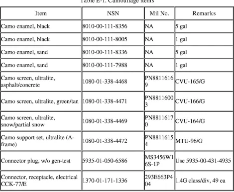
Table E-llists standard camouflage items available to the soldier. Items on this list are ordered through normal unit-procurement channels:
.
A complete list of Department of Defense (DOD) stock materials is available from theDefense Logistics Service Center (DLSC), Battle Creek, Michigan, Defense Switched Network (DSN) 932-4725 or commercial (616) 961-4725.
.
A complete list of Army materials is available from the Army Materiel Command (AMC), Logistics Support Activity, Redstone Arsenal, Alabama, DSN 645-0782 or commercial (205) 955-0782.Control, remote smoke gen,
1080-01-338-7051 PN8811551 For SG-18-02
IMXK-856/E32 0
Decoy target, bailey bridge 1080-00-650-1098
~r
52165 one
Decoy target, how, 105-mm 1080-00-570-6519 MIL-D- PN EB 306D4904- IT08 52165B
Decoy units, inflating, radar,
5865-01-266-3840 MRIIRVIN Passive radar freq
~/SLQ-49 820/821 espondent
Decoy, aircraft, ground (F-16) 11080-01-301-8273 IpN160002 IOnly 25 produced
Decoy, close combat, MIAI
1080-01- 242-7251 PN13277E9r
tank 830 one
Decoy, close combat, M60A3
1080-01-242-7250 PN3228E19r
tank 79 one
Decoy, runway (FOS) 1080-01-338-5201 ~N8811610
~Ox 1,000 ft
Diesel fuel, DF-l 19140-00-286-5288 Ivv -F-800Dlsmoke/Obsc-alt
Diesel fuel, DF-2 19140-00-286-5296 Ivv -F-800Dlsmoke/Obsc-alt
Diesel fuel, DF-2 19140-00-286-5297 Ivv -F-800Dlsmoke/Obsc-alt
Drum, S&S, 55-gal 18110-00-292-9783 ~A 18-gauge steel, painted
Drum, S&S, 55-gal 18110-00-597-2353 ~A 16-gauge steel, painted
IExplosive, airburst projectile
1055-01-175-4002 FN102575 Smoky flak, LMK-25 launch atk
tFederal standard colors 595- B 7690-01-162-2210
F
2-ft x lO-in fan deck ofcolor
Gen set, smoke, mech, M157 1040-01-206-0147 PN31-15- rone 255
Gen, signal radio freq 16625-00-937 -4029 ~A ISM-422/GRC
Gen, smoke, mech, M3A 1040-00-587-3618 MILSTD60 None 4
~~STD60
I
Gen, smoke, mech, M3A4 1040-01-143-9506 PN E31-15-2000
Indiv camo cover, 3-color
8415-01-280-3098
~woodland 4358 8 OZ,5- x 8-ft coverage
Indiv camo cover, 6-color desert 8415-01-280-5234
~8OZ,5- x 8-ft coverage
4358
Indiv camo cover, snow 8415-01-282-3160
~8OZ,5- x 8-ft coverage
4358
lLauncher rckt, I-bay launcher,
1055-01-131-7857 PN1335AS
I
tLMU -23E 380 Smoky SAM
launcher rckt, 4-bay launcher,
1055-01-144-0864 PN1335AS
I
OMU-24E 700 Smoky SAM
lcss support set, desert 1080-00-623-7295 ~Canuse
1080-01-253-52765 0522
lcss support set, snow 1080-00- 556-4954 ~Sameas
1080-01-179-52765 6024
tLcss support set, woodland 1080-00-108-1173 ~Sameas
1080-01-179-52765 6025
lcss support set, woodland 1080-00-108-1173 ~Plasticpoles 52765
tLcss, desert, radar-scattering 1080-00-103-1211 ~Canuse
1080-01-266-52771 1828
ILcss, desert, radar-scattering 1080-01-266-1825 PN13228E5 Can use
1080-01-266-930 1828
ILcss, desert, radar-scattering 1080-01-266-1828 PN13228E5 Use 1080-01-266-1825
933 first
lcss, desert, radar-transparent 1080-00-103-1217 C52765 ~PN13226E1357
lcss, snow, radar-scattering 1080-00-103-1233 ~Canuse
lcss, snow, radar-scattering 1080-00-103-1234 MIL-C- PN13226E1355 52765
lcss, snow, radar-scattering 1080-01-266-1823 PN13228E5 Can use
1080-01-266-928 1826
lcss, snow, radar-scattering 1080-01-266-1826 PN13228E5 Can use
1080-00-103-931 1233
ILCSS, woodland,
radar-1080-00-103-1246 ~Canuse
1080-01-266-scattering 53004 1827
lcss, woodland,
radar-1080-00-103-1322 ~PN13226E1356
scattering 53004
ILCSS, woodland,
radar-1080-01-266-1824 PN13228E5 Can use
1080-01-266-scattering 929 1827
lcss, woodland,
radar-1080-01-266-1827 PN13228E5 Use 1080-01-266-1824
scattering 932 first
lLead acid btry, 24V, BB-297U 16140-00-059-3528 ~S75047-1For SG 18-02 w/o gen
!Mounting kit, smoke gen, M284 1040-01-249-0272 PN31-14- For M157 gen 2680
lNet, multipurpose, olive-green
8465-00-889-3771 ~108-x 60-in coverage
mesh 3181
Paint, temp, tan 8010-01-326-8078 52905 ~Ped-std-595B 33446
Paint, temp, tan 8010-01-326-8079 52905 ~Fed-std-595B 33446
Paint, temp, white 8010-01-129-5444
~r
52905 one
Pump inflating, manual, smoky
r3 20-00- 822 -9036
r-p-746
Need 1 ea TO
llA-l-flak 46
Reflector, radar, Coast Guard
2050-01-225-2779
F
1 cu ft, lO-lb,Ibuoy marker aluminum
Simulator, atomic explosion,
1370-00-474-0270 MIL-S- FM8864243
Simulator, projectile airburst,
1370-01-180-5856 PN102549 1.1G class/diy, 48 ea
pm-7/E
Simulator, projectile airburst,
1370-01-279-9505 PN8387310 1.3G class/diy, 48 ea
pm-7A/E
Smoke pot, 30-lb, HC, M5 1365-00-598-5207 ~PHE36-1-18, 17 min
13183
Smoke pot, floating, HC 1365-00-939-6599
~w
/M208/M209 fuse51235
Smoke pot, floating, HC, M4A2 1365-00-598-5220 MIL-S- w/M207a fuse, 12 min 51235B
Smokey SAM rocket, GTR -18A 1340-01-130-6282 DL1335AS Firing cartridge and
100 ocket
Support poles, camo net, ultralite 1080-01-338-4470 PN8811615 MTU-99/G,2
3 poles/battens
Tool, special purpose, smoky
5120-01-176-2188 FN103320 Feed 1 ea flak
Trailer, ground-handling,
MHU-1740-01-031-5868 ~BK- 5,500-lb cap, for
SG-141/M 300 18-02
Valve adapter assy, smoky flak 1055-01- 216-4803 PN8523971
F
d 1 h
-10 ee eac
Valve, pneumatic tank, smoky
r820-00-4 27-5047 fV500RK2Feed 1 ea flak
Kvrench, bung 5120-00-045-5055 Cage
~-x -in pIngs
Appendix F
The Geneva Emblem
and Camouflage
of Medical Facilities
I
This appendix implements STANAG 2931.
I STANAG 2931 covers procedures for using the Geneva emblem and camouflaging medical facilities. This STANAG requires signatories to display the Geneva emblem (red
cross) on medical facilities to help identify and protect the sick and wounded. All signatories, however, are allowed to display the Geneva emblem according to their national regulations and procedures. STANAG 2931 also defines medical facilities as
medical units, medical vehicles, and medical aircraft on the ground. A tactical commander may order the camouflage of medical facilities, including the Geneva emblem, when the failure to do so will endanger or compromise tactical operations. Such
an order is considered temporary and must be rescinded as soon as the tactical situation permits. The camouflage of large, fixed medical facilities is not envisaged under the