ABSTRACT
MACKEY, LANDON KENT. Ultrafast Direct Current Protection Systems for Faster Fault Isolation in Multi-terminal LVDC and MVDC Distribution. (Under the direction of Dr. Iqbal Husain.)
Energy has quickly risen to be one of the key factors affecting modern society. Finite resources of
fossil fuels contribute to pollution, destabilization, and climate change. The energy sector is making
efforts to shift heating and transportation to electric energy from carbon based fuels while shifting the
generation of electricity from the conventional centralized, fossil fuel and nuclear heavy system
towards more distributed and renewable energy means. Many emerging technologies in distributed
renewable energy are non-synchronous or direct current in nature. The proliferation of power
semiconductors and power electronics allows cost effective and efficient voltage manipulation in direct
current that was not available at the dawn of the modern electric system, which relied on the
wire-wound transformer for voltage transformation. Despite these advancements, the great challenge
facing direct current distribution systems is providing safe, fast, efficient, and affordable protection
systems to maintain system stability and isolate faults. Direct current protection systems must isolate
faults without the aid of a natural current zero crossing, without consuming large amounts of energy,
and on a sub-millisecond timescale. The focus of this doctoral study and research project is to explore
direct current system dynamics during fault, review available technologies, identify viable protection
topologies, and design new methods of safety interrupting medium voltage direct current faults. This
study revealed many elements that are necessary for effective isolation of direct current faults, primarily
the ability to appropriately manage the surge energy and to provide isolation fast enough to prevent
voltage collapse in power electronic converter dominated distribution systems. Direct current faults
have been characterized using analytical analysis of fault condition, computer simulation software, and
testing of grid connected converters in the laboratory. The resulting characteristics provided the basis
for the list of requirements for developed medium voltage direct current circuit breakers. Circuit
breaker designs were simulated using computer models such as PLECS, PSCAD, COMSOL, Matlab and
Simulink and testing in the laboratory using functional test prototypes at both reduced scale and full
power capacity. It is found that each of the reviewed circuit breaker topologies studied, designed, and
most efficient, yet operates too slowly and cannot quench a drawn electrical arc alone. The resonant
circuit breaker is the lowest cost and highly efficient, however is limited to overcurrent fault isolation.
The solid-state circuit breaker is highly controllable; the fastest of all designs, yet consumes significant
power and requires active cooling while in operation. Finally, the hybrid circuit breaker is highly
efficient, fast enough to prevent voltage collapse, and controllable for all fault conditions, however is
the most expensive of available topologies. As a result of this research, a new type of hybrid direct
current circuit breaker has been designed, and is currently under second generation development for
medium voltage applications. The so-called Progressively Switched Hybrid Circuit Breaker is a
bidirectional full function circuit breaker that minimizes the surge on the power system, limits fault
current during shutdown, and ensures maximum efficiency during operation. A scalable medium
voltage second-generation circuit breaker is under development with aims of isolating faults between
© Copyright 2019 by Landon Kent Mackey
Ultrafast Direct Current Protection Systems for Faster Fault Isolation in Multi-terminal LVDC and MVDC Distribution
by
Landon Kent Mackey
A dissertation submitted to the Graduate Faculty of North Carolina State University
in partial fulfillment of the requirements for the Degree of
Doctor of Philosophy
Electrical Engineering
Raleigh, North Carolina
2019
APPROVED BY:
Dr. Srdjan Lukic Dr. Leonard White
Dr. Gregory Buckner Dr. Iqbal Husain
DEDICATION
This work is dedicated to all those who are working diligently to make this world a better place for
BIOGRAPHY
The author was born in Michigan, USA. He received the Bachelor of Science degree in Electrical
Engineering with a concentration on Renewable Electrical Energy Systems (REES) and the Master of
Science in Electrical Power Systems Engineering from North Carolina State University, Raleigh, USA in
2015 and 2016 respectively. Since January of 2017 he has been pursueing the Doctorate of Philosophy in
Electrical Engineering at North Carolina State University at the Future Renewable Electric Energy
Delivery and Management (FREEDM) Systems Center, Raleigh, USA.
He began his work in the direct current (DC) microgrid field during six years of military service in
the United States Navy where he operated and maintained the nuclear power plant of a Los Angeles
class nuclear fast attack submarine. Throughout his education he continued to pursue experience
outside of the classroom through internships at ABB Corporate Research Center, Dättwil, Aargau,
Switzerland developing a next generation Modular Multilevel Converter testing platform, and at Ford
Motor Company, Dearborn, Michigan, USA developing dc fast charge integration systems for battery
electric vehicles. He participated in undergraduate research under the guidance of Dr. Iqbal Husain
during the final year of his B.S. degree researching Future Smart DC Distribution Grids, and worked
with industry sponsor Pos-En ® to develop a Modular Energy Generator for deployment in Costa Rica
to support critical infrastructure. Throughout graduate school he has mentored undergraduate
students and peers, worked with advocacy groups of under-represented minorities in the sciences,
served on several student leadership boards, and project teams to maintain active involvement with
and provide support to his community.
His research interests include developing technologies and system which promote the
integration of distributed renewable energy resources to the electric grid, or developing islanded direct
current microgrids supplied by renewable energy. Future goals in the field include continued
contribution towards the next generation electric grid including smart grid, a direct current electric
ACKNOWLEDGEMENTS
Thank you to all of my friends, family, and colleagues who have supported me through my journey of
life. I especially thank Dr. Iqbal Husain for seeing my potential, and investing in my future. Your
mentorship and guidance has been instrumental in my accomplishments, and have helped to develop
me into the man I am today.
I would also like to thank coffee for waking me up, beer for calming me down, and backpacking
TABLE OF CONTENTS
LIST OF TABLES . . . ix
LIST OF FIGURES. . . x
TERMINOLOGY . . . xv
Chapter 1 Low and Medium Voltage Direct Current Multi-terminal Distribution and Pro-tection . . . 1
1.1 Introduction . . . 1
1.2 Global Trends Toward the Adoption of Direct Current Systems . . . 2
1.3 Advantages of Direct Current Distribution . . . 3
1.3.1 Low Voltage Direct Current Applications . . . 5
1.3.2 High Voltage Direct Current Transmission . . . 6
1.3.3 Islanded and Non-conventional DC Distribution Systems . . . 6
1.4 Challenge of Protecting Direct Current Systems . . . 7
1.4.1 Interruption Speed . . . 7
1.4.2 Absence of a Current Zero-Crossing . . . 8
1.4.3 Organization of Subsequent Chapters . . . 10
Chapter 2 DC Circuit Protection Technologies: A Review of Proposed Topologies . . . 11
2.1 Existing Solutions for Protecting Direct Current Systems . . . 11
2.2 DC Circuit Breakers . . . 12
2.2.1 Mechanical Circuit Breakers . . . 13
2.2.2 Resonant Style Circuit Breakers . . . 13
2.2.3 Solid-State Circuit Breakers . . . 15
2.2.4 Hybrid Circuit Breakers . . . 16
2.3 Medium Voltage Direct Current Distribution Protection . . . 17
Chapter 3 Active Damping and Advanced Control of a Thomson Coil Actuated Ultrafast
Me-chanical Switch . . . 19
3.1 Thomson coil actuated ultrafast mechanical switches for hybrid DC circuit breaker . . . 19
3.2 Reclosing issue with passive damping mechanism . . . 23
3.3 Proposed active damping for Thomson coil actuated switches . . . 24
3.4 Design of the active damping control . . . 28
3.5 Experimental tests of active damping . . . 30
3.5.1 Test Setup . . . 31
3.5.2 Measurement and Control of Test Setup . . . 31
3.5.3 Comparison of COMSOL simulation with test results . . . 33
3.5.4 Contribution of opening voltage . . . 35
3.5.5 Contribution of damping voltage . . . 38
3.5.6 Contribution of damping pulse timing . . . 39
3.6 Lessons Learned . . . 41
3.7 Conclusions . . . 42
Chapter 4 Design and Optimization of a Mechanically Switched Z-Source Resonant DCCB . . 44
4.1 Introduction . . . 44
4.1.1 Background of Z-Source Circuit Breakers . . . 45
4.1.2 Background of Ultrafast Mechanical Switches . . . 47
4.2 Circuit Breaker Design . . . 47
4.2.1 Simulation . . . 48
4.2.2 Analytical Assessment . . . 49
4.2.3 Test Bench Experimentation . . . 51
4.3 Comparison of Simulation, Analytical and Experimental Platforms . . . 54
4.4 Result and Analysis . . . 55
4.5 Preliminary Design Conclusions . . . 57
4.6 Background of the Z-Source Topology . . . 58
4.7 Mechanically Switched Z-Source DCCB . . . 59
4.7.1 Efficiency Improvement with Mechanically Switches . . . 61
4.7.2 Arcing Challenge in DC Mechanical Switches . . . 62
4.8 Analysis of System Response and Simulation . . . 64
4.8.1 System Dynamics During Bolted Fault . . . 64
4.8.2 System Dynamics During Step Change in Load . . . 67
4.9 Mechanically Switched Z-Source Design . . . 68
4.9.1 Zero-Crossing Time Calculation . . . 68
4.9.2 Component Optimization . . . 69
4.9.3 Control and Protection Logic . . . 71
4.10 Simulation and Prototype Results . . . 73
4.10.1 Simulation Validation . . . 73
4.10.2 Experimental Test Prototype Results . . . 74
4.10.3 Comparison with Other DCCBs . . . 76
4.11 Conclusion . . . 77
Chapter 5 Progressively Switched Solid-State and Hybrid Direct Current Circuit Breakers. . 79
5.1 Introduction . . . 79
5.2 DC Fault Characteristics . . . 81
5.3 Progressively Switched Solid-State DCCB . . . 83
5.3.1 Progressively Switched DCCB Design . . . 84
5.3.2 Progressively Switched DCCB Capabilities . . . 85
5.3.3 Progressively Switched DCCB Test Prototype . . . 87
5.4 Results . . . 87
5.4.1 Two-Stage Progressively Switched DCCB Results . . . 88
5.4.2 Four-Stage Progressively Switched DCCB Results . . . 88
5.4.3 Validation of Computer Model with Test Prototype . . . 91
5.5 Solid-State Circuit Breaker Conclusions . . . 92
5.7 DC Protection . . . 93
5.7.1 DC Distribution Fault Characterization . . . 93
5.7.2 Isolation Speed Challenge with Hybrid DCCBs . . . 95
5.8 Proposed Progressive Switching of Hybrid DCCBs . . . 96
5.9 Prototype Design . . . 102
5.9.1 Progressively Switched Main Breaker . . . 102
5.9.2 Actively Damped Ultrafast Mechanical Switch . . . 103
5.9.3 Modular Commutating Switch . . . 105
5.9.4 Integrated Sensing, Communication, and Breaker Controls . . . 106
5.10 Experimental Results . . . 107
5.11 Conclusions and Summary . . . 108
Chapter 6 Conclusions and Future Work - Scalability of Progressively Switched Hybrid Cir-cuit Breakers . . . .111
6.1 Scalability of Progressive Main Breakers . . . 111
6.2 Laboratory Scaling of the Progressively Switched DCCB Prototype . . . 112
6.3 Scalability Considerations . . . 114
6.3.1 Presspack Solid-State Switches and Puck Style MOVs . . . 114
6.3.2 Radial Lead Solid-State Switches and Radial Lead MOVs . . . 115
6.3.3 Module Topology Solid-State Switches and Module MOVs . . . 116
LIST OF TABLES
Table 3.1 Combinations of opening voltages, damping voltages and damping delays tested. 31
Table 4.1 Experimental Setup Parameters. . . 52
Table 4.2 Circuit Breaker Design and Test Parameters . . . 60
Table 4.3 Mechanical Switch Compared to Thyristor . . . 62
Table 4.4 Mechanical Switch Test Parameters . . . 63
Table 4.5 Comparison of Analytical and Simulation Models . . . 67
Table 4.6 Simulation Results for LS y s=2.5 mH, LE Q =10 mH and CE Q=190µF . . . 73
Table 4.7 Simulation Results for LS y s=1 mH, LE Q =10 mH and CE Q=190µF . . . 73
Table 4.8 Experimental Test Results . . . 76
Table 5.1 Four-Stage Progressive DCCB Parameters . . . 88
Table 5.2 Dielectric Strength of UFMS . . . 105
Table 5.3 Progressively switched hybrid DCCB parameters . . . 109
LIST OF FIGURES
Figure 1.1 Illustration of the global trend towards DC systems. . . 2
Figure 1.2 Many conversion steps between centralized generation and end consumer. . . . 3
Figure 1.3 A DC microgrid interconnected to the legacy AC grid and a DC microgrid. . . 4
Figure 1.4 Rapid voltage collapse of a DC distribution system compared to AC system. . . . 8
Figure 1.5 AC fault with a repetitive current-zero crossing facilitating fault isolation. . . 9
Figure 1.6 Direct current, pulsating, and variable current sources do not guarantee a current zero crossing. . . 10
Figure 2.1 Oscillatory mechanical circuit breaker. . . 14
Figure 2.2 Resonant style circuit breaker. . . 14
Figure 2.3 Solid-state circuit breaker. . . 16
Figure 2.4 Hybrid circuit breaker. . . 17
Figure 3.1 A hybrid DC circuit breaker (DCCB). . . 20
Figure 3.2 Diagram of the Thomson coil actuator based fast mechanical switch. . . 21
Figure 3.3 Design of the ultrafast mechanical switch. . . 22
Figure 3.4 The ultrafast mechanical switch prototype. The based plate is approximately 30 cm by 30 cm. . . 23
Figure 3.5 Successful opening driven by 400 V. . . 24
Figure 3.6 Opening driven by 420 V followed by a reclosing. . . 25
Figure 3.7 Multiphyics interaction in the actuator. . . 26
Figure 3.8 3D view of the FEM model. . . 26
Figure 3.9 Induced current in the disc, 60µs after energizing the opening coil, simulation in axisymmetric 2D view. . . 27
Figure 3.10 Induced current in the disc, 440µs after energizing the damping coil, simulation in axisymmetric 2D view. . . 27
Figure 3.12 Driving force (from 0 to 2 ms) and damping forces (from 2 to 4 ms), simulation
results. . . 29
Figure 3.13 Speed and displacement curves corresponding to Fig. 3.12 forces, simulation
results. . . 30
Figure 3.14 Test setup of the active damping method. . . 32
Figure 3.15 Opening operations with varying opening voltages and damping delays with a
damping voltage of 322 V. . . 32
Figure 3.16 Opening operations with varying opening voltages and damping delays with a
damping voltage of 345 V. . . 33
Figure 3.17 Measurement and control diagram of the Thomson coil actuated, actively
dam-ped, ultrafast mechanical switch. . . 34
Figure 3.18 Comparison of Experimental test-bench results to COMSOL simulated results. . 35
Figure 3.19 UFMS motion for various opening voltages, with 2.0 ms damping delay and 322
V damping voltage. . . 36
Figure 3.20 UFMS motion for various opening voltages, with 2.0 ms damping delay and 345
V damping voltage. . . 37
Figure 3.21 UFMS motion for various opening voltages, with 3.0 ms damping delay and 322
V damping voltage. . . 37
Figure 3.22 UFMS motion for various opening voltages, with 3.0 ms damping delay and 345
V damping voltage. . . 38
Figure 3.23 UFMS motion for various opening and damping voltages, with 3.0 ms delay. . . . 39
Figure 3.24 UFMS motion for various damping pulse timings with 430 V opening voltage and
322 V damping voltage. . . 40
Figure 3.25 UFMS motion for various damping pulse timings with 430 V opening voltage and
345 V damping voltage. . . 40
Figure 3.26 UFMS velocity pattern for various opening voltages, with 2.0 ms damping delay
and 322 V damping voltage . . . 41
Figure 3.27 UFMS velocity pattern for various opening voltages, with 3.0 ms damping delay
Figure 4.1 Z-Source Circuit Breaker Circuit Diagram . . . 46
Figure 4.2 FREEDM Systems Center Ultra-Fast Mechanical Switch Prototype (IEEE 2016) . 48 Figure 4.3 Simulation setup in PSCAD . . . 49
Figure 4.4 Voltage and current profile of UFMS (top) and energy absorbed and current inrush to MOV (bottom). . . 50
Figure 4.5 Current ripple and voltage ripple induced in the fast mechanical switch and impedance network during fault condition. . . 50
Figure 4.6 Z-Source Circuit Breaker Simplified Analytical Schematic . . . 51
Figure 4.7 Z-Source Circuit Breaker Test Bench Prototype . . . 52
Figure 4.8 Z-Source Circuit Breaker Source Current. . . 53
Figure 4.9 Z-Source Circuit Breaker Switch Current. . . 54
Figure 4.10 Experimental Z-Source Circuit Breaker Source (solid lines) and Switch Current (dashed lines). . . 54
Figure 4.11 Experimental and Simulation Source Current. . . 55
Figure 4.12 Experimental and Simulation Switch Current. . . 56
Figure 4.13 Comparison of Theoretical and Experimentald td i to voltage . . . 56
Figure 4.14 Prototype Isolation of Mechanically Switch Z-Source Circuit Breaker . . . 57
Figure 4.15 Bidirectional, mechanically switched Z-Source DCCB . . . 61
Figure 4.16 Mechanical switch isolation waveform with (a) 10 A and (b) 22 A . . . 63
Figure 4.17 Z-Source circuit breaker simplified analytical schematic . . . 64
Figure 4.18 Experimental current transient time comparison with (blue)LS y s=0m H and (orange)LS y s=2.5m H . . . 66
Figure 4.19 Zero crossingst1&t2and compensated nonlineart20 . . . 70
Figure 4.20 Optimization distribution oft20withL/C ratio . . . 71
Figure 4.21 Logic flow diagram of protective action . . . 72
Figure 4.22 Z-Source test prototype experimental waveform . . . 74
Figure 4.23 Z-Source circuit breaker test prototype waveform . . . 75
Figure 4.24 Z-Source circuit breaker test prototype waveform . . . 76
Figure 5.1 Comparison of typical DC and AC fault differences during short circuit fault
conditions . . . 81
Figure 5.2 Comparison of progressive switching voltage and current simulation output of 1, 4 and 8 switching steps . . . 83
Figure 5.3 Progressively switched solid-state DCCB schematic (shown with 4 stages) . . . 84
Figure 5.4 Four-stage, 380VD C, progressively switched solid-state DCCB . . . 86
Figure 5.5 Two-stage progressively switched DCCB experimental test waveforms . . . 87
Figure 5.6 Four-stage progressively switched 380 volt DCCB test bench . . . 89
Figure 5.7 Four-stage progressively switched DCCB infrared image during continuous ope-ration . . . 89
Figure 5.8 Four-stage progressively switched DCCB experimental test waveforms . . . 90
Figure 5.9 Four-stage progressively switched DCCB experimental test waveforms . . . 91
Figure 5.10 Four-stage progressively switched DCCB experimental test waveforms . . . 91
Figure 5.11 Simplified analytical model of a hybrid DCCB . . . 94
Figure 5.12 Opening sequence of a hybrid DCCB . . . 96
Figure 5.13 Operation of a hybrid DCCB . . . 97
Figure 5.14 Progressively switched, actively damped UFMS hybrid DCCB functional diagram 98 Figure 5.15 Progressively switched hybrid DCCB schematic . . . 98
Figure 5.16 Operation of proposed progressive hybrid DCCB . . . 100
Figure 5.17 Simulation of 2ms UFMS operating in a 1 stage hybrid DCCB, and 4 stage and 8 stage progressively switched hybrid DCCBs . . . 101
Figure 5.18 Simulation of progressively switched DCCB . . . 101
Figure 5.19 Four-stage progressively switched MB . . . 103
Figure 5.20 Four-stage progressively switched MB experimental test waveforms . . . 104
Figure 5.21 UFMS vacuum gap vs. time . . . 104
Figure 5.22 Control logic flowchart for progressive shutdown . . . 107
Figure 5.23 Progressively switched, actively damped UFMS, hybrid DCCB test prototype . . . 108
Figure 5.25 Current, voltage and displacement waveforms from progressive hybrid test,
pro-cessed for clarity . . . 109
Figure 6.1 Output current and voltage waveforms of an early 25 volt, 2.5 amp, 2 stage pro-gressively switched solid-state DCCB . . . 113
Figure 6.2 Output current and voltage waveforms of the 425 volt, 20 amp, 4 stage progressi-vely switched hybrid DCCB . . . 113
Figure 6.3 Output current and voltage waveforms of the 1,000 volt, 3 amp, 4 stage progressi-vely switched solid-state DCCB . . . 114
Figure 6.4 Presspack solid-state switch device . . . 115
Figure 6.5 Puck style MOVs . . . 115
Figure 6.6 TO-247 style radial lead MOSFET package . . . 116
Figure 6.7 Radial lead style MOVs . . . 116
Figure 6.8 Module style solid-state switches . . . 117
Figure 6.9 PSCAD Fault Simulation Diagram of 15 kV Modular DCCB . . . 117
Figure 6.10 PSCAD Schematic of 15 kV Modular DCCB . . . 117
TERMINOLOGY
AC Alternating current
CS Commutating switch
DC Direct current
DCCB Direct current circuit breaker
DSP Digital signal processor
ESFI Electrical Safety Foundation International
FEM Finite element method
HVAC High voltage alternating current
HVDC High voltage direct current
IEC International Electrotechnical Commission
IEEE Institute of Electrical and Electronic Engineers
IEGT Injection-enhanced gate transistor
IGCT Integrated gate-commutated thyristor
IGBT Insulated-gate bipolar transistor
LED Light emitting diode
LVDC Low voltage direct current
MB Main breaker
MMF Magnetomotive force
MOSFET Metal oxide field effect transistor
MOV Metal oxide varistor
MVDC Medium voltage direct current
NEC National Electric Code
NFPA National Fire Protection Association
OSHA Occuptational Safety & Health Administration
SiC Silicon Carbide
TCA Thomson coil actuator
TRV Transient recovery voltage
UFMS Ultrafast mechanical switch
VSC Voltage source converter
CHAPTER
1
LOW AND MEDIUM VOLTAGE DIRECT
CURRENT MULTI-TERMINAL
DISTRIBUTION AND PROTECTION
1.1 Introduction
The production, transmission, and distribution of electric energy comprises one of the largest
infrastructure networks ever created, yet it is still rapidly growing. The International Energy Agency
estimates that 1.1 billion people, approximately 14% of the global population is does not yet have access
to electric energy, however global energy consumption continues to rise. The existing electric energy
distribution infrastructure originates back to the late nineteenth century where centralized generation
far away from the consumer is transmitted to the population regions, voltages is adjusted accordingly
electric grid continues to evolve and adopt new technologies, this legacy system exhibits its struggle to
meet changing requirements, and new options to manage global energy distribution must be assessed.
This preliminary dissertation analyzes a growing global trend toward direct current (DC) loads,
generation sources, and distribution networks and deals with the most significant challenge facing DC
systems, circuit protection. DC circuit protection has unique requirements and presents new obstacles
that are not associated with conventional alternating current (AC) system protection.
1.2 Global Trends Toward the Adoption of Direct Current Systems
Direct current devices are tenaciously expanding throughout modern society and infrastructure from
low to high voltage levels. The low voltage sector shows drastic growth in portable consumer
electronics, light emitting diode (LED) lighting, digital systems, electrified transportation, and inverter
driven appliances as illustrated in Fig. 1.1.
Figure 1.1Illustration of the global trend towards DC systems.
Similarly, high voltage direct current (HVDC) bulk power transfer dominates the modern electric
power transmission sector across the world, proving to be more efficient, higher power density, and
more cost effective than traditional high voltage alternating current (HVAC) overhead lines. However,
power from centralized power stations unidirectionally to the end consumer. This poses significant
challenges to the electric distribution infrastructure to adopt the proliferating distributed renewable
energy resources which may cause bidirectional power flow on legacy systems, affect voltage droop
profiles, and bypass protective features. The legacy alternating current distribution system requires
multiple stages of conversion between alternating and direct current to finally arrive at the load, which
is likely direct current, resulting in costly and inefficient electric power distribution as shown in Fig. 1.2.
Figure 1.2Many conversion steps between centralized generation and end consumer.
The introduction of semiconductors has lead to exponential growth in DC systems. These devices
allow the modification of voltage levels without need of a magnetic field, allowing DC voltages to be
stepped up and down with ease, and paved the way for the digital age. Nearly all residential and
commercial energy is consumed in direct current, with industrial applications being the primary
consumer of line-fed AC energy.
1.3 Advantages of Direct Current Distribution
Direct current energy sources, such as solar farms; and DC loads, like portable electronics, occupy an
ever growing presence on the modern electric grid. A DC distribution network would eliminate tens of
millions of AC to DC converters that are used in nearly all of our devices. Every portable electronic
device, digital system, inverter driven devices, and more are entirely DC. This was established early on
to the immediate uptake of DC in all motor vehicles. A DC grid can be stand-alone, known as islanded,
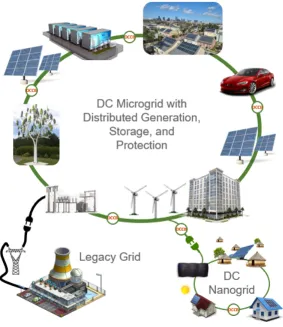
or can be grid connected to the legacy power system, as shown in Fig. 1.3.
Figure 1.3A DC microgrid interconnected to the legacy AC grid and a DC microgrid.
Several of the many advantages of DC distribution over the legacy AC distribution system include:
1. No skin effect.The entire diameter of a cable is used for DC distribution rather than the outer 8.5 mm used at 60 Hz due to the skin effect, resulting in more effective use of cables and overhead
lines.
2. Only real power.With no frequency component, the only controlable aspect of a DC grid is the voltage level for power sharing. As such generators or converters have an additional degree of
3. Fewer Conductors.DC systems require only two or three conductors, dependent upon the neutral reference point arrangement. AC systems require a minimum of 4 conductors for
traditional three phase operation.
4. No Magnetic Field.Without a time varying current component, a magnetic field is not generated, this results in reduced corona discharge, no proximity effect, and no interference to surrounding
personnel or equipment.
5. HVDC to MVDC Conversion.Current conversion to and from HVDC to AC transmission levels requires large valve stations including reactors, capacitor banks, grid frequency matching, and
additional equipment. HVDC to MVDC conversion is drastically simplified without the need for
such reactive compensation.
6. No Frequency Control.Connection to the DC distribution grid does not require frequency matching, enabling ease of distributed generation connection.
7. Offshore Energy Harvesting.HVDC is the primary means of transmitting offshore wind power to shore for consumption. However, this currently requires the windfarm be operated
synchronously, collected as an offshore substation, converted to HVDC, transmitted to shore for
conversion back to AC for distribution. This process would be greatly simplified with a meshed
DC grid and would expand the ability of other offshore energy harvesting technologies[1].
8. Enhanced Controlability.Voltage source converters that dominate DC distribution systems are able to compensate for changes in load on the nanosecond level, dependent upon switching
frequency. Comparable AC systems rely upon mechanical governors and electric field adjustment
to correct for load changes.
1.3.1 Low Voltage Direct Current Applications
All computerized and digital electronics operate on LVDC and are well suited for DC microgrids to
ensure sensitive electronics are not susceptible to interference[2]. 380 Volt DC distribution has already
been identified as a common low voltage distribution level with uptake widely seen in battery banks,
system, low voltage DC distribution also maintains the highest level of stability and continuity through
selected tripping of protection devices[4]. Portable electronics ranging from very small and low power devices such as pace-makers and watches ranging ot high power large devices such as electric vehicles
are all direct current. At an even larger scale, chemical energy storage is growing in popularity to stiffen
electric grids and reduce the intermittency of renewable energy resources like wind and solar energy.
Low voltage DC applications are generally easier to protect at low power levels and is achieved by fuses,
power electronic switches, small relays or other mechanical switches that are able to manage the arc
that is drawn.
1.3.2 High Voltage Direct Current Transmission
HVDC is not limited by the insulation rating of transformers as modern HVDC valve stations are able to
achieve voltages exceeding one megavolt[5]. These ultra-high voltages, cominbined with lack of skin
effect or proximity effect and the need for only two conductors makes far less expensive than long
distances AC transmission. Additionally, with minimal time varying component, HVDC observes
reduced power loss and environmental impacts due to corona discharge[6].
HVDC systems at this point in time are all two-terminal systems for bulk power transfer and have
no DC side protection. This means that if a fault were to occur or if the system needed to be secured,
the entire two-terminal system is shut down at each end. Therefore DC circuit protection is not
required until such a point in time that HVDC systems branch into multi-terminal networks.
1.3.3 Islanded and Non-conventional DC Distribution Systems
An increasing number of applications which are not connected to the existing utility grid are designed
and operated in purely DC. Space flight and exploration are all entirely DC as they operate on
photovoltaic (PV) and radioisotope thermal generation (RTG) which both produce direct current. As
nearly all loads on spacecraft are DC and they are not connected to the terrestrial electric grid, there is
no need for AC on these missions. Modern aircraft systems are increasingly utilizing multiple power
electronic converter systems for conversion and conditioning of the power system, which is in most
aircraft, entirely DC[7]. The Navy and large marine ships are investigating the use of multiple small
to shift toward electric pod propulsion, replacing the conventional shaft driven propeller. Shipboard DC
distribution allows for smaller, more fuel efficient generators to be ran at their optimum efficiency
speed rather than dictated by the ship speed requirement or the frequency of the bus. Transoceanic
cargo liners who do not connect to shore power frequently are under scrutiny due to large diesel engines
running for days on end while ships are loaded and unloaded at port just to provide auxiliary power to
the ship, which could be accomplished more efficiently with a small DC generator connected to the bus.
Other islanded applications include off-shore energy harvesting beyond that of just wind, which has
already established DC as the subsea transmission medium of choice and coastal desalination.
1.4 Challenge of Protecting Direct Current Systems
Although the applications and generation sources are available for DC distribution, the challenge
remains to safely protect these systems by interrupting the current in the event of a fault. Modeling of
DC distribution systems is far more dynamic than for AC systems, specifically based upon energy
storage and distributed generation and the individual dynamics of each converter, therefore event
based protection is required to ensure protection is provided under all circumstances[9]. The most
accepted and capable means of fault detection and locating is through Differential Protection Strategies
[10–12]. Differential detection does have limitations due to traveling waves, interference, and
harmonics injected to the line through the grid connected converters[13]. Centralized Protection Strategies are also possible, yet require low latency communication to all devices in the distribution
network[14]. DC faults can pose exceptionally demanding protection challenges in terms of speed of
propogation and fault current magnitude due connected energy storage and fast response time of
Voltage Source Converters (VSCs)[15].
Two primary challenges are exhibited in interrupting fault current in multiterminal DC circuits,
interruption speed and the lack of a current zero crossing.
1.4.1 Interruption Speed
Low system inductance from decoupling of motors and generators through power electronics results in
faults rise much faster in DC systems than in AC systems, as shown in the first few milliseconds of Fig.
two or three time greater than nominal fault current for several milliseconds before experiencing
voltage collapse of the system. Therefore, DC circuit breakers must operate in several milliseconds,
rather than 30 to 70 milliseconds that are common for AC electromechanical circuit breakers. The
widely accepted time for showing DC distribution protection has been 5 milliseconds, however recent
publications and Advance Research Projects Agency-Energy (ARPA-E) solicitations are pursuing
protection methods as fast as 500 microseconds.
Figure 1.4Rapid voltage collapse of a DC distribution system compared to AC system.
1.4.2 Absence of a Current Zero-Crossing
In AC systems, there is a natural current zero crossing point on each phase at a rate of21f, or once every
10 to 8.3 milliseconds for 50 and 60 Hz, respectively. This provides a recurring and natural point for any
arc that is drawn to be subsequently extinguished provided that the dielectric strength of the
overcurrent fault in an AC distribution system, even with a large DC offset at the beginning of the
envelope, the current waveform continues to cross zero periodically until it is extinguished. This allows
any mechanical switch which can open contacts far enough to overcome the voltage differential
between the contacts to interupt an AC fault whether it be an open air contact, oil bath, vacuum, or for
high voltage switches, Sodium Hexafloride (S F6) or other gas.
Figure 1.5AC fault with a repetitive current-zero crossing facilitating fault isolation.
However, DC does not cross zero at any time, this removes the systems natural ability to
commutate any arc that is drawn. This same occurance is found in pulse power applications, such as a
Wave Energy Converter (WEC) which creates current pulses as it moves back and forth in the surf, or
variable current sources, such as a bouy or other non linear generator as shown in Fig. 1.6.
Without a symmetrical current to balance the energy and to ensure a zero crossing, natural fault
current commutation cannot be used to interupt faults in these systems. Therefore not only does the
current need to be forced to zero by an artificial means, but the non-symmetrical energy must be
managed. The following section identifies methods to force the current to zero and absorb the transient
Figure 1.6Direct current, pulsating, and variable current sources do not guarantee a current zero crossing.
1.4.3 Organization of Subsequent Chapters
The rest of this dissertation reviews work done to date, and planned future work in the field.
• Chapter 2 - DC Circuit Protection Technologies: A Review of Proposed Topologies
• Chapter 3 - Active Damping and Advanced Control of a Thomson Coil Actuated Ultrafast
Mechanical Switch
• Chapter 4 - Design and Optimization of a Mechanically Switched Z-Source Resonant DCCB
• Chapter 5 - Progressively Switched Solid-State and Hybrid Direct Current Circuit Breakers
• Chapter 6 - Conclusions and Future Work - Scalability of Progressively Switched Hybrid Circuit
CHAPTER
2
DC CIRCUIT PROTECTION
TECHNOLOGIES: A REVIEW OF PROPOSED
TOPOLOGIES
2.1 Existing Solutions for Protecting Direct Current Systems
There are several methods that can be employed to isolate a DC system fault:
1. Fuses:Thermal fuses are common in low voltage and lower power systems where a metalic element is heated during an over current condition to the point of melting, creating an open
contact and securing current flow. This method absorbs the excess energy through the thermal
action of destroying the element and then must be replaced to reintroduce current flow once the
fault condition is corrected. This solution is commonly used in 12 VDC systems in automobiles
several hundred volts, dependent upon system dynamics, as large enough current surge or fault
condition will ionize the air between the two contacts and continue to supply fault current.
2. De-energize the System:Securing all sources of energy to the system will isolate a DC fault quickly, as the power electronic converters that supply DC systems can be shutdown in
microseconds. Once all generation sources are shutdown, the remaining energy in the system will
be discharged through the fault or operational loads and the fault condition will stop, and the
system can be re-energized once the condition that caused the fault is corrected. This is common
in HVDC or other two-terminal systems where shutting down of the entire system would be the
same as isolating the fault, however if there are multiple generation sources, and multiple
terminals, this will cause all devices on the system to lose power. Additionally, in the event that
multiple generation sources are feeding the fault, the shutdown must be coordinated to secure all
sources to the fault at the same time, to prevent damage to any one converter that is left to supply
the fault current alone, requiring a centralized control strategy.
3. Circuit BreakersA circuit breaker is a device that locally determines if a fault condition occurs and stops the current from flowing using a switch. The switching device can be mechanical or
solid-state. Circuit breakers come in many different shapes, sizes, and styles and can be designed
to operate locally or remotely, and can provide many types of circuit protection in addition to
over current conditions such as under-voltage, over power, rate of current change, and many
more. These are the most flexible and dependable circuit protection devices and can be designed
for all voltage levels.
2.2 DC Circuit Breakers
Direct current circuit breakers (DCCBs) provide the highest degree of controlability, protection, and
flexibility for multiterminal DC distribution systems. However, DCCBs must operate within
milliseconds to provide protection, and manage the transient energy that would be discharged through
2.2.1 Mechanical Circuit Breakers
Mechanical circuit breakers create a gap between contacts either in air, vacuum, oil, or a non-ionizing
gas likeS F6in high voltage circuit breaker switches. Mechanical DCCBs are able to draw and quench an arc either through oscillation such as a capacitive discharge as shown below in a oscillatory mechanical
circuit breaker in Fig 2.1. Up to several hundred volts and at low currents, some devices are able to
create a large mechanical gap between contacts or insert an insulating separation device to quench the
arc. These devices are commonly used at lower power applications such as small rooftop solar arrays
Mechanical DCCBs can be operated by springs, solenoids, repulsion coil, pneumatic, or
hydraulic actuators. To achieve millisecond level protection and to keep the devices simple, most are
either solenoid or repulsion coil coil actuated. It is important to note that a mechanical switch is not a
DC circuit breaker. A mechanical DCCB must have a means in which to absorb or counteract the
transient energy and quench any arc that is drawn during a fault isolation condition. In Fig. 2.1 the arc
is counteracted through the discharge of the capacitor in the parallel branch and any excess energy
from the transient surge or the capacitive discharge is dissipated in the surge arrestor as heat.
Mechanical DCCBs are the most efficient and robust as they do not require any cooling and they
have relatively zero on state power consumption. However, these devices are the slowest of all DCCBs
and are generally limited to lower power levels as high power arcs are difficult to interrupt without
catastrophic damage to the device.
2.2.2 Resonant Style Circuit Breakers
Resonant style circuit breakers, such as a Z-Source circuit breaker shown in Fig. 2.2 create an artificial
current zero through resonant ringing between energy storage devices and commutate off the thyristor
iS C R by reverse biasing it during the resonant transient. Many arrangements of resonant circuit
breakers have been designed and tested, yet all operate based on the same principle of exchanging
energy between two or more energy storage devices at their resonant frequency during transient.
Resonant circuit breakers are very fast to operate and relatively inexpensive to build, and in the
case of the thyristor based Z-Source DCCB shown in Fig. 2.2 provides automatic overcurrent protection
Figure 2.1Oscillatory mechanical circuit breaker.
to the power handling capability of the thyristor that full load current must pass through, creating an
on-state power consumption. However, without significant additional complexity they are
unidirectional and only offer over-current protection, as even manual operation of these DCCBs
requires that a current transient be introduced in the system, placing strain on the converters, loads,
and the circuit breaker itself
2.2.3 Solid-State Circuit Breakers
Solid-state circuit breakers can be used with a variety of components and can be either unidirectional
or bidirectional by design[16, 17]. Although similar in design to the mechanical DCCB, a solid-state
circuit breaker does not draw an arc, it opens a doped channel within the semiconductor device which
stops electron flow, with the exception of a small leakage current. Solid-state DCCBs must be used in
conjunction with a snubber and/or an arrestor to absorb the energy in the system as shown in Fig. 2.3. The solid-state switch is opened within several nanoseconds of the gate signal being removed, therefore
the system inertia due to any inductance in the system, parasitic or by design, will cause a rapid
over-voltage condition at the device terminals, which will destroy the device if the surge exceeds the
voltage rating. Some of the most common solid-state switches used in solid-state circuit breakers
include:
• IGBT - Insulated Gate Bipolar Transistor
• IGCT - Integrated Gate-Commutated Thyristor
• GTO - Gate Turn Off Thyristor
• IEGT - Injection-Enhanced Gate Transistor
• ETO - Emitter Turn Off Thyristor
• SCR - Silicon Controlled Rectifier
• MOSFET - Metal Oxide Field Effect Transistor
• JFET - Junction Field Effect Transistor
Each component has a unique characteristic dependent upon the needs of the application, as
some have a constant voltage dropVdsuch as SCR and IGBT, where some have a temperature constant
on-state resistance,Rd s,o n, such as MOSFET and JFET. Others are normally on or normally off, have
either current or voltage dependant gates, etc.
Solid-state circuit breakers are the fastest and most energy dense of the DCCBs and they are fully
circuit breaker, a solid-state DCCB relies on the sensing and control of an outside digital signal
processor or controller. Solid-state DCCBs have significant on-state power consumption leading to
reduced efficiency, and need for supplemental cooling in many applications. Operation during a fault is
also limited to the thermal handling capabilities defined by the device based upon theI2T curve for each specific device, which determines how quickly the device will self-heat as current increases during
an overcurrent fault condition.
Figure 2.3Solid-state circuit breaker.
2.2.4 Hybrid Circuit Breakers
A hybrid circuit breaker combines the high efficiency of a mechanical normal current path and the high
speed power electronic shutdown capabilities of a solid-state DCCB as shown in Fig. 2.4. Together these
two designs provide high speed, controllability, and efficiency. During operation normal load current is
directed through the fast mechanical switch, and a commutating switch, also known as a auxiliary
circuit breaker. In the event of a fault the main breaker turns on and the commutating switch turns off,
redirecting current through the main breaker. Then the fast mechanical switch opens under no-current
condition, mitigating any arc from being drawn across its contacts. Once the fast mechanical switch is
open, the main breaker turns off and stops current flow the same way that the solid-state DCCB does.
Hybrid circuit breakers are capable of achieving very high power levels with minimal on state
power loss through the commutating switch. These circuit breakers are dependent upon the speed of
the fast mechanical switch as the limiting factor for full isolation and shutdown. Advances in repulsion
Hybrid circuit breakers hold the greatest possibility to balance the high efficiency requirements
of a DC distribution system, while providing adequate isolation times to ensure system stability. Hybrid
DCCBs while more efficient than a solid-state DCCB do have the drawbacks of slower operation time,
and higher system cost, due to the construction of effectively two circuit breakers in parallel.
Figure 2.4Hybrid circuit breaker.
2.3 Medium Voltage Direct Current Distribution Protection
Medium voltage direct current (MVDC) is identified as a promising solution to the aging legacy electric
grid, and is being actively pursued for non-grid connected applications such as electrified
transportation including, Navy and shipping, high speed rail, aviation, hyperloop, and electric personal
vehicles.
This research is funded by, and in support of, the University of North Carolina (UNC) Coastal
Studies Institute (CSI) North Carolina Renewable Ocean Energy Program (NCROEP). This research has
generated technologies aimed at meeting the NCROEP mission of facilitate the study of, harnessing,
and distribution of energy harvest off-shore from a variety of renewable energy resources.
MVDC Distribution and Protection provide many benefits beyond renewable ocean energy
harvesting as well, such as:
• Distributed generation and storage
• Electrification and Decentralization
• Distributed Renewable Electrical Energy Resources
• Transportation Paradigm Shift
• Transactive Energy Markets and "Prosumers"
• Military Applications (Navy, Aviation, Forward deployed units)
• Cruise Ships and other Maritime Applications
• Installation and Maintenance Platforms (Oil, offshore wind, floating drydocks)
2.4 Dissertation Purpose
This preliminary dissertation identifies the challenges and proposes solutions to the most difficult
aspect of low and medium voltage direct current systems, DC circuit breakers. The fundamental
challenge of DC circuit protection is investigated and requirements for low and medium voltage
distribution circuit protection are established based upon system dynamics and fault response. Finally,
solutions for high speed, high efficiency, bidirectional circuit protection are presented in theory,
CHAPTER
3
ACTIVE DAMPING AND ADVANCED
CONTROL OF A THOMSON COIL
ACTUATED ULTRAFAST MECHANICAL
SWITCH
3.1 Thomson coil actuated ultrafast mechanical switches for hybrid DC circuit breaker
Medium and high voltage hybrid DC circuit breakers combine electronic switches with mechanical
switches in parallel[18–23]. They consist of four primary components for current conducting, commutation and interruption as shown in Fig. 3.1; an ultrafast mechanical switch (UFMS) or
disconnector, a low voltage solid state switch as the commutating switch (CS), a high voltage solid state
composed of anti-series IGBTs, denoted as two IGBT symbols with diodes in the diagram. They in fact
represent strings of devices to meet the requirement of the nominal voltage rating. The hybrid solid
state DC circuit breaker scheme that exploits a low voltage commutating switch in series with an
ultrafast mechanical disconnector provides an ultrafast and highly efficient protection solution to
power systems[19, 20]. In normal conduction, the current flows through the nominal path that consists
of UFMS and CS. In order to interrupt a fault current, first the CS turns off in a few microseconds and
commutates current into the MB in a few tens of microseconds. The UFMS opens and forms a gap
between its contacts that can withstand the high voltage that will result from the subsequent turn-off of
MB.
Though this concept was originally proposed to interrupt a DC circuit, it fits AC applications as
well. As a matter of fact, since the interruption operation is finished as fast as in a couple of
milliseconds, it is faster than usual AC periods (at 50 or 60 Hz), such that an AC circuit acts like a DC
circuit as far as the hybrid circuit breaker is concerned. Because of the sub-quarter cycle operation, the
hybrid circuit breaker can therefore also limit the fault current in AC circuits.
The effectiveness of these hybrid AC and DC circuit breakers is predicated on the mechanical
switch opening as fast as possible to obtain a sufficient gap between the open contacts, so that they can
withstand the transient recovery voltage (TRV) following current interruption. This is because the total
interruption time of the hybrid circuit breaker is dominated by the operation speed of the UFMS in
such hybrid circuit breakers[18, 19, 24–27].
Figure 3.2Diagram of the Thomson coil actuator based fast mechanical switch.
The switches used in this type of circuit breakers are typically based on electromagnetic
repulsion forces with current induced in a conductive copper disc (so-called Thomson coil actuator)
[24, 25, 27]. The switch actually comprises two coils, one for the opening operation and one for the
closing operation, located on either side of the copper disc (above and underneath, Figs. 3.2 and 3.3. To
open the UFMS, the opening coil is energized so that a strong magnetic field is generated which
penetrates into the conductive disc. This time varying magnetic field induces azimuthal eddy currents
in the disc which in turn create an opposing magnetic field. These two fields oppose each other and a
repulsive force is generated between the coil and the disc. Closing is obtained in a similar manner with
the lower coil.
In this paper, an active damping mechanism and its control are proposed for this type of actuator.
The goal is to absorb the kinetic energy at the end of motion, avoiding over-travel, bounce, and the like.
In doing so it becomes possible to actually excite the opening coil to higher levels, resulting in overall
faster operation than would be possible without the active damping. This result will contribute to
achieving ultrafast operation for the switches and therefore the hybrid DC circuit breakers. With this
control, superior performance is achieved. Further, the structure remains simple without adding extra
damping mechanisms. Smaller vacuum interrupters can be used and the size of the overall switch
on the issue of DC current breaking are facing the same difficulties. Similarly, in[27], the velocity of the
moving part is seen increasing up to the end of motion, reaching a high 5 to 6 ms , with no damping
mechanism included in the design to absorb the corresponding kinetic energy upon end-of-motion
impact. The present paper adds to the literature a comprehensive parametric analysis as well as
experimental investigations. The experimental study provides valuable quantitative results on different
combinations of driving conditions of the opening and damping operations.
The paper includes finite element modeling of the active damping transients and test results
obtained on a 15kV/630A/1ms mechanical switch. The actuator design used in this study is described
in details in[25], and the drive circuits have been discussed in[26]. The content of this study were
originally presented at the 2016 ECCE Conference[25].
Figure 3.4The ultrafast mechanical switch prototype. The based plate is approximately 30 cm by 30 cm.
3.2 Reclosing issue with passive damping mechanism
The general issue addressed in this paper is the design of effective, reliable damping mechanisms to
absorb the kinetic energy due to fast opening. Mechanical means are effective, but need to be tuned to
the energy imparted to the system during opening. Not enough damping can lead to damage, and too
much generates bounce and long effective travel time. If the bounce is large enough, the system
recloses (opening failure). Therefore, a fixed damping can actually limit the opening energy and
lengthen the travel time, by forcing the designer to use a level of energy below that which will lead to
bounce. This was observed during initial tests of a prototype switch (shown in Fig. 5.4). In order to
illustrate this, Fig. 3.5 shows a successful opening with a capacitor bank that is precharged to 400 V. The
displacement curve is linear, overshoots and finally settles at a steady state open position. When driven
by 420 V however, see Fig. 3.6, the travel is initially faster but at the end of the travel and following the
overshoot the switch does not stay at a steady state open position. Instead it bounces back towards the
non-linear disc springs (see[4]for a more detailed description of the design). Other mechanisms are
possible[29–31]but all are expected to suffer from the same limitation due to their being set at the design stage, with no feedback control possible. With damping disc springs a few factors can affect the
damping process, such as:
1. The kinetic energy of the moving mass. Most of the energy is to be absorbed by the disc springs.
2. The non-linear load-versus-deflection characteristic of the disc spring (see[25]) and how much
energy the disc spring can absorb. The disc spring provides holding forces both at the open and
closed positions which correspond to different operation points on the load-versus-deflection
curve.
3. The allowable over-travel during opening. Two components limit this over-travel range: the
vacuum interrupter and the disc spring. A longer over-travel results in larger sizes for both
components and therefore the overall size of the switch assembly.
Figure 3.5Successful opening driven by 400 V.
3.3 Proposed active damping for Thomson coil actuated switches
This paper proposes an active damping method that utilizes the Thomson coils of such an actuator and
does not require extra mechanical complexities in structure and design.
When the mechanical switch is to open, a large amount of energy is dumped into the opening
Figure 3.6Opening driven by 420 V followed by a reclosing.
method, as the fast opening is completed and the required gap is obtained, the closing coil is energized
and used as a damping coil to generate a reverse, braking force which slows down the movement. Then
the disc spring can easily handle the remaining kinetic energy and secure the moving parts in the open
position.
The approach is developed here in the context of repulsion coils. It can be extended, at least in
principle, to any actuator with two (or more) coils acting in opposite directions. Some work in that area
was done, for instance, on actuators with permanent magnets[32–34].
The research was carried out first by comprehensive transient finite element method (FEM)
simulation, complemented by experimental evaluation. The physical equations solved by COMSOL
include Maxwell’s Equations in the opening coil, the closing coil and in the conductive disc, as well as
the mechanical balance of force between the electromagnetic forces as derived from Maxwell’s, spring
forces, gravitational forces and friction losses.
These supporting equations have been published in previous work completed under this project
[20], and similar equations were provided elsewhere[27].
The FEM modeling includes different physics (electromagnetic, mechanical, and thermal), see
Fig. 3.7. The mechanical actuator is designed for a 630 A prototype at medium voltage range (15-50 kV).
The model geometry is shown in Fig. 3.8. Two typical snapshots of the simulated transients are
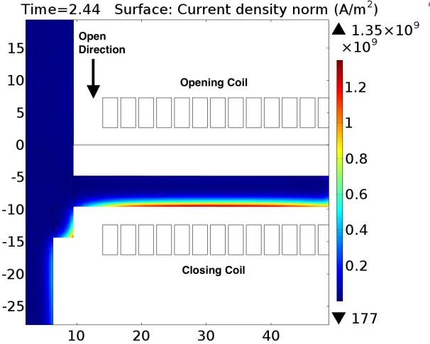
presented in Figs. 3.9 and 3.10 to illustrate the eddy currents induced in the conductive copper disc
upon the energization of the opening coil and the damping coil, respectively.
Figure 3.7Multiphyics interaction in the actuator.
Figure 3.83D view of the FEM model.
opening transient when the opening coil is driven by a moderate voltage level of 355 V. The travel
reaches 3 mm at 2 ms and settles to a steady state position of approximately 7-8 mm with 1.5 mm
overshoot. When opening voltage is as high as 415 V (the purple curve), the moving contact overshoots
more than 2 mm and recloses because the excessive kinetic energy is not damped out by the
Figure 3.9Induced current in the disc, 60µs after energizing the opening coil, simulation in axisymmetric 2D view.
Figure 3.10Induced current in the disc, 440µs after energizing the damping coil, simulation in axisymmetric 2D
view.
Therefore, the active damping method is proved to enable higher speed operation and prevent
voltage can be even higher, such as 430 V, so that faster opening operation can be achieved.
Figure 3.11Damped and undamped operations.
3.4 Design of the active damping control
The general principle of active damping was presented in Section III. This section addresses how to
design the damping control, or in other words when and by how much the damping coil should be
energized. For a given pulse of the opening coil, there are a few variables in the damping pulse that can
be changed to achieve the best performance for a given design of an UFMS. They correspond to the
timing, magnitude, and shape of the damping pulse, the magnitude and shape being controlled by the
capacitance and voltage of the capacitor bank exciting the damping coil. If the same capacitor bank is
used for both opening and closing operation, as is preferable for simplicity and to minimize cost, it is
also the same for the damping operation. Therefore timing is the most convenient parameter to affect
the damping performance. Voltage and capacitance may be used as additional degrees of freedom, if
their impact on performance justifies the extra complexity.
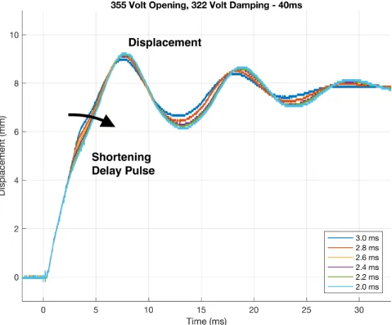
Figs. 3.12 and 3.13 illustrate the active damping effects, as calculated by transient FEM modeling
to Fig. 3.12, a negative force accelerates the moving mass, starting at time 0. Then, a positive force later
dampens the movement, starting at time 2 ms or later (several model runs are superimposed on the
same graph, all starting with the same opening pulse). Fig. 3.13 shows the corresponding displacements
(solid traces) and velocities (dashed curves).
Figure 3.12Driving force (from 0 to 2 ms) and damping forces (from 2 to 4 ms), simulation results.
With a capacitor bank of 2 mF pre-charged to 400 V, the actuator is accelerated to 2.6 m/s (Fig.
3.13). At 2 ms, the gap in the switch reaches 4.5 mm which can withstand 60 kV. A sweep of delay times
from 2.0 ms to 3.0 ms is presented in Figs. 3.12 and 3.13, and the following observations can be made:
1. Energizing the braking coil has an immediate effect to dampen the opening movement. Braking
therefore should not be initiated before the specified gap and opening time are reached, 4.5mm
and 2ms, respectively, in this case.
2. The later the damping coil is energized, the closer the copper discs proximity is to the damping
coil at time of actuation, therefore the damping force increases. Conversely, with shorter delays,
the disc may be too far for the damping coil to have any substantial effect, the disc being out of
range, so to speak. The largest peak damping force was obtained with a 3 ms delay. It is 160
Figure 3.13Speed and displacement curves corresponding to Fig. 3.12 forces, simulation results.
There is therefore an opportunity for optimization, with later pulses being more powerful, but
intervening farther in the travel. Fig. 3.13 shows when the damping force starts to operate, and
also shows the position at which the disc comes to a stop.
3. An earlier damping pulse results in a weaker force and takes a longer time to reduce the kinetic
energy of the moving mass. But the travel is limited to a smaller range (the disc stops at position 6
mm at time 4 ms).
4. A later damping results in a stronger force, takes a shorter time to reduce the kinetic energy of the
moving mass. However, the movable contact tends to travel further (7.7 mm at 4 ms).
3.5 Experimental tests of active damping
Experimental tests were performed on a Thomson coil actuated ultrafast mechanical switch to verify
the approach and the FEM model. These results provide additional validation of both the calculated
parameters of active damping, and the interactions that occur between the repulsion coils and the
Table 3.1Combinations of opening voltages, damping voltages and damping delays tested.
Opening voltage Damping voltage Damping delay
• 355 V
• 370 V
• 385 V
• 400 V
• 415 V
• 430 V
• 322 V
• 345 V
• 365 V (for selected opening voltage and delay values)
• 2.0 ms
• 2.2 ms
• 2.4 ms
• 2.6 ms
• 2.8 ms
• 3.0 ms
3.5.1 Test Setup
A prototype of a Thomson coil actuated ultrafast mechanical switch and associated driving mechanism
was modified to test the active damping approach in a laboratory setting. More details regarding the
mechanical switch can be found in[25]. The closing coil was used as the damping coil; two capacitor
banks of the same capacitance were independently controlled by two thyristor switches to energize the
opening coil and the damping coil. The physical setup is shown in Fig. 3.14.
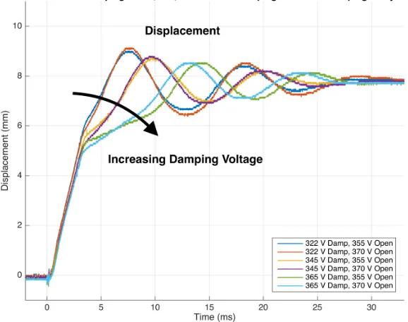
The test setup allows incremental variations of the opening coil voltage, damping coil voltage,
and trigger delay between the opening and damping current pulses. Testing has been conducted using
the parameters listed in Tab. 3.1. Figs. 3.15 and 3.16 show which combinations of parameters led to a
successful opening, and which led to reclosure.
3.5.2 Measurement and Control of Test Setup
A high level measurement and control diagram shown in Fig. 3.17 represents the control inputs and
measurement outputs from the prototype test bench. Two programmable DC power sup plies charge
the opening and closing coil capacitor banks, which are then discharged through the Thomson Coils via
power thyristors. The User inputs and control, annotated in green in Fig. 3.17 control the timing delay
and voltage applied which is variable for experimentation. In red, the measurements of the system
Figure 3.14Test setup of the active damping method.
Figure 3.15Opening operations with varying opening voltages and damping delays with a damping voltage of
Figure 3.16Opening operations with varying opening voltages and damping delays with a damping voltage of 345 V.
• Current pulse applied to the opening and closing coils via a Rogowski current sensor
• Control signal to the opening coil
• Control signal to the damping coil
• Voltage signal from a linear potentiometer mounted to the shaft of the movable mass
The voltage signal generated by the linear potentiometer on the shaft is mathematically equated
to position, and the derivative of this signal is the movable masses velocity. Together these
measurements are used to track the position, speed, and signals associated with operation with respect
to time. The test bench offers great flexibility in operating the Ultrafast mechanical switch under
variable conditions to systematically test variable operating conditions, as described in the following
sections of this paper.
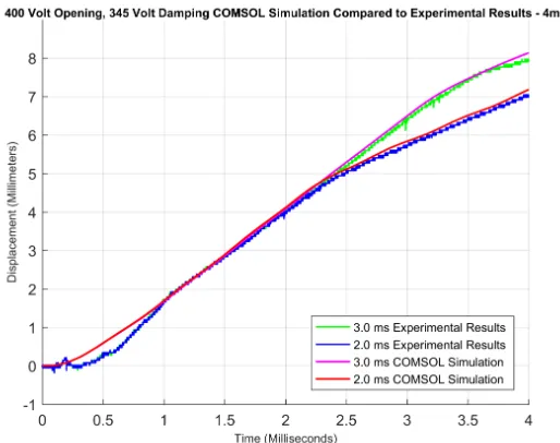
3.5.3 Comparison of COMSOL simulation with test results
Simulation accuracy is verified through comparison of the COMSOL multiphysics simulation and the
Figure 3.17Measurement and control diagram of the Thomson coil actuated, actively damped, ultrafast mechanical switch.
Volt opening and 345 Volt damping simulation with experiment. Two cases are shown corresponding to
damping-pulse delays of 2.0 ms and 3.0 ms. The timing, velocity and overall shape of simulated and
test-bench results verify the accuracy of the model after the 1 ms point. Deviation between simulated
and experimental data within the first millisecond are likely due to the following sources of error not
accounted for in modeling:
1. Stiction of the two physical bodies that requires additional force to overcome stationary friction
prior to beginning motion. The simulation did not include stiction.
characteristic. Although the spring and its non-linearity were modeled, its exact characteric may
have lacked precision over a portion or all of the spring force-displacement curve.
3. Contact slippage or lag of potentiometer position sensor due to the rapid acceleration of the
moving mass.
4. The COMSOL simulation predicts force which is then compared to motion, amplifying any error
in the double integral.
Figure 3.18Comparison of Experimental test-bench results to COMSOL simulated results.
3.5.4 Contribution of opening voltage
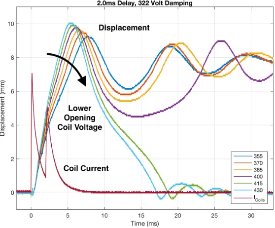
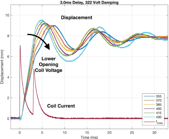
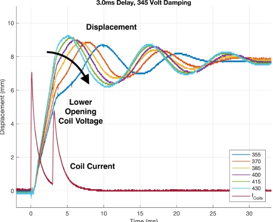
The impact of opening voltage for a fixed damping delay (either 2 ms or 3 ms) is shown as displacement
curves in Figs. 3.19 to 3.22. Also shown in the figures, for reference, is one trace corresponding to the
current pulses in the opening and damping coils. The force exerted on the movable mass for opening
and therefore the acceleration of the opening contacts are controlled through the opening voltage
applied to the opening coil. Increasing this opening voltage and therefore the magnitude of the current