Hardware Reference Manual
s
t
n
e
m
m
o
C
R
e
v
.
N
o
.
D
a
t
e
e s a e l e R l a i t i n
I 707020-001 7/23/99
e t a d p U a r a s i
This is the Communications Server Hardware Reference Manual. For
information on the LINCS Operating System, please visit our website,
www.visara.com.
1. From your Internet browser type http://www.visara.com
2. Select Support
3. Select Manuals
The 1174 Communications Servers comply with relevant product safety standards, such as the UL and CSA, and TUV-GS Rules and Regulations.
FCC and CDC Regulatory Statements
This equipment has been tested and found to comply with the limits for a Class A computing device, pursuant to Part 15 of the FCC Rules. These limits are designed to provide reasonable protection against harmful interference in a commercial installation. This equipment generates, uses, and can radiate radio frequency energy and, if not installed and used in accordance with the instructions, may cause harmful interference to radio communications. However, there is no guarantee that interference will not occur in a particular installation. If this equipment does cause harmful interference to radio or television reception, which can be determined by turning the equipment off and on, the user is encouraged to try to correct the interference by using one or more of the following measures:
• Reorient or relocate the receiving antenna.
• Increase the separation between the equipment and the receiver.
• Connect the equipment into an outlet on a circuit different from that to which the receiver is connected.
• Consult the dealer or an experienced radio/TV technician for help.
This equipment has been certified to comply with the limits for a Class A computing device, pursuant to FCC Rules. In order to maintain compliance with FCC regulations, shielded cable must be used with this equipment. Operation with nonapproved equipment or unshielded cables is likely to result in interference to radio and TV reception. The user is cautioned that changes and modifications made to the equipment without the approval of the manufacturer could void the user’s authority to operate this equipment. The user may find the following booklet prepared by the Federal Communications Commission helpful:
How to Identify and Resolve Radio-TV Interference Problems
This booklet is available from the U.S. Government Printing Office, Washington DC 20402, Stock No. 004-000-00345-4.
This digital apparatus does not exceed the Class A limits for radio noise emissions from digital apparatus set out in the Radio Interference Regulations of the Canadian Department of Communications.
Table of Contents
Read This First ... iii
Product Safety ... iv
FCC and CDC Regulatory Statements ... iv
1. Introduction ... 1
General Description ... 1
1174-65S Hardware Components ... 1
1174-90S Hardware Components ... 2
2. Installation ... 3
Checklist ... 3
Printed Circuit Boards ... 3
Unpacking Printed Circuit Boards (PCBs) ... 3
Installing/Removing Circuit Boards ... 3
Location Planning for the 1174 ... 4
Environmental Parameters ... 4
Power Requirements ... 4
Maximum Cable Distance ... 4
Power Cable Requirements ... 6
Connections ... 7
3270 Host Connection ... 7
Token Ring Connection (TRC) ... 7
Ethernet Connection (ETH) - 65S only (No longer offered) ... 7
LED Descriptions ... 9
ASCII Host/Device Cabling (65S only) ... 10
Coax Device Attachment ... 10
Dynamic Multiplexing ... 10
1174-65S Device Attachment ... 11
1174-90S Device Attachment ... 12
High Speed Communication Interface (65S only) ... 13
Cabling ... 13
RS232 Serial Interface ... 14
3. Board Population ... 17
Introduction ... 17
Printed Circuit Board Names ... 17
Board Types Used ... 17
Slot Population ... 18
1174-65S ... 18
1174-90S ... 18
Slot Identification ... 19
Slot Numbers ... 19
Logical Identifiers ... 20
Board ID Assignments ... 20
4. Operation ... 21
Indicators ... 21
Operator Panel LEDs ... 21
High Speed Communication Interface ... 21
Controls ... 22
Power Switch ... 22
IML Procedure for 90S and 65S ... 23
Additional IML Options for 65S ... 23
Error Types ... 24
IML Errors (ERR ___) ... 24
Exception Errors (XCP ___) ... 24
Hardware Failures (FAIL ___) ... 25
Online Errors ... 25
Error Indicators ... 26
Event Log ... 26
Operator Panel Display ... 26
Operator Panel Check Light ... 26
Software Merge (65S only) ... 26
Warning Messages ... 27
Failure Messages ... 27
5. Assembly Removal/Replacement ... 29
Introduction ... 29
1174-65S/90S ... 29
Assembly Drawing ... 29
Replaceable Assemblies ... 30
Covers ... 30
Circuit Board Assembly ... 30
Power Supply Assembly ... 31
Operator Panel ... 31
Floppy Disk Drive ... 32
Hard Disk Drive (65S only) ... 32
Memory Module ... 33
Mother Board Assembly ... 33
General Description
The 1174 Communications Server family is a powerful platform for supporting and managing diverse networks. The 1174-90S and the 1174-65S Communications Servers support only LINCS software and are part of the Communications Server hardware family.
Information presented in this manual includes procedures for hardware installation, basic operating instructions, and assembly removal and replacement instructions for the 1174-65S/ 90S Communications Servers.
1174-65S Hardware Components
The following table includes hardware that may be installed in the 1174-65S. Refer to Chapter 2, Memory Requirements, to determine the maximum number of each dual-port memory board for installation.
m e t I e r a w d r a
H Max#
d e l l a t s n
I Function
e c a f r e t n I I I C S A ) y l b m e s s a A D A h t i w C I A ( 1 s e d i v o r p ) B C P C I A ( r e l l o r t n o C e c a f r e t n I I I C S A e h T e h t a i v s t s o h / s e c i v e d I I C S A 8 o t p u r o f t r o p p u s e c a f r e t n i . y l b m e s s a ) A D A ( r e t p a d A e c i v e D I I C S A r e t p a d A e c i v e D x a o C ) A D C ( 2 e p y t A -x a o C 2 3 o t p u r o f n o i t c e n n o c t c e r i d s e d i v o r P . s d r a o b t r o p -8 1 d n a t r o p -9 n i e l b a l i a v a A D C . s e c i v e d . s r e x e l p i t l u m x a o c o t e c a f r e t n i s e d i v o r p o s l A ) H T E ( t e n r e h t
E 3* Providescommunicationinterfacingto10Mpbs . T E F y b d e c a l p e R . d e r e f f o r e g n o l o N . s k r o w t e n t e n r e h t E e v i r D k s i D y p p o l
F 1 Datastorage.Providesmeanstoloadnewsoftwareto . e v i r d k s i d d r a h e c i v e D c i t p O r e b i F ) A O F ( r e t p a d A 1 . s k n i l r e x e l p i t l u m c i t p o r e b i f g n i s u r o f t r o p p u s s e d i v o r P a t c e n n o c o t x a o c e l g n i s a s a h o s l a A O F n A . d e r e f f o r e g n o l o N . x a o c a i v x u m t r o p -2 3 e v i r D k s i D d r a
H 1 Datastorage.Mutuallyexclusiveofsecondfloppydisk . e v i r d e c n a m r o f r e P h g i H ) P P H ( r o s s e c o r P 3 . s e r u t a e f e m o s y b d e d e e n g n i s s e c o r p l a n o i t i d d a s e d i v o r P . P H V y b d e c a l p e R . d e r e f f o r e g n o l o N d e e p S h g i H ) C S H ( s n o i t a c i n u m m o
C 3*
C L D S o t e c a f r e t n i s n o i t a c i n u m m o c e t o m e r d e e p s h g i H . s e n i l 4 o t p u s e d i v o r P . s k r o w t e n y a l e R e m a r F d n a s e d a r g p u ) M E M ( y r o m e
M N/A Uptoamaximumof4MBytesofupgradememory. d r a o B r e h t o
M 1 ContainscircuitryforSCP,MCC,andSHAfunctions. l e n a P r o t a r e p
O 1 Provideslocaloperatorinterfacetothecontroller. y l p p u S r e w o
P 1 Providesstablepowertothecontroller. r e t p a d A t s o H I S C S ) n o i t c n u f A H S
( N/A
r e h t o M f o t r a p , e v i r d k s i d d r a h e n o r o f l o r t n o c s e d i v o r P . y r t i u c r i c d r a o B s n o i t a c i n u m m o C l a i r e S ) C C S ( r e l l o r t n o
C 3*
m e t I e r a w d r a
H Max#
d e l l a t s n
I Function
r o s s e c o r P l o r t n o C m e t s y S ) n o i t c n u f P C S
( N/A
f o t r a p , g n i s s e c o r p d n a l o r t n o c m e t s y s l l a s e d i v o r P . y r t i u c r i c d r a o B r e h t o M r e l l o r t n o C g n i R n e k o T ) I I C R T
( 3*
a o t g n i c a f r e t n i n o i t a c i n u m m o c l a c i s y h p s e d i v o r P . k r o w t e n g n i r n e k o t d e e p S h g i H y r e V ) P H V ( r o s s e c o r
P V 2*
s e v o r p m I . g n i s s e c o r p m a e r t s a t a d s e t a r e l e c c A f o r e b m u n e h t s e s a e r c n i d n a e c n a m r o f r e p g n i k r o w t e n . d e t r o p p u s e b n a c t a h t s n o i s s e s ) T E F ( C I N t e n r e h t E t s a
F 3* Providesphysicalcommunicationinterfacingto s k r o w t e n t e n r e h t e s p b M 0 0 1 / 0 1
* A maximum of 3 slots exist for the installation of SCC, HSC, FET, TRCII, ETH, and VHP cards.
† One VHP is required if any of these features are installed: Telnet Host, Print Serving, more than 32 incoming Telnet sessions or Lan printers, or if there are more than 512 3270 Host sessions. Another VHP is required if the APPN feature is installed.
1174-90S Hardware Components
The following table includes hardware that may be installed in the 1174-90S. Refer to Chapter 2, Memory Requirements, to determine the maximum number of each dual-port memory board for installation.
m e t I e r a w d r a
H Max#
d e l l a t s n
I Function
r e t p a d A e c i v e D x a o C ) A D C ( 1 s e c i v e d e p y t A -x a o C o t n o i t c e n n o c t c e r i d s e d i v o r P . y l n o s d r a o b t r o p -9 n i e l b a l i a v a A D C e v i r D k s i D y p p o l
F 2 Datastorage. s e d a r g p u ) M E M ( y r o m e
M N/A Nomemoryupgrades. d r a o B r e h t o
M 1 ContainscircuitryforSCP,MCC,andSHAfunctions. l e n a P r o t a r e p
O 1 Provideslocaloperatorinterfacewiththe . r e v r e S s n o i t a c i n u m m o C y l p p u S r e w o
P 1 ProvidesstablepowertotheCommunicationsServer. r e t p a d A t s o H I S C S ) n o i t c n u f A H S
( N/A
f o t r a p , e v i r d k s i d d r a h e n o r o f l o r t n o c s e d i v o r P . y r t i u c r i c d r a o B r e h t o M s n o i t a c i n u m m o C l a i r e S ) C C S ( r e l l o r t n o C 1 . s r e t u p m o c 0 7 2 3 o t s s e c c a n o i t a c i n u m m o c s e d i v o r P ) S 0 9 -4 7 1 1 l l a n o d r a d n a t S ( r o s s e c o r P l o r t n o C m e t s y S ) n o i t c n u f P C S
( N\A
f o t r a p , g n i s s e c o r p d n a l o r t n o c m e t s y s l l a s e d i v o r P . y r t i u c r i c d r a o B r e h t o M r e l l o r t n o C g n i R n e k o T ) I I C R T ( 1* a o t g n i c a f r e t n i n o i t a c i n u m m o c l a c i s y h p s e d i v o r P . e t i s i u q e r o c a s i e r a w t f o S S C N I L . k r o w t e n g n i r n e k o t . t e n r e h t E t s a F r o t e n r e h t E n a h t i w e v i s u l c x e y l l a u t u M ) T E F ( C I N t e n r e h t E t s a F 1* 0 0 1 a o t g n i c a f r e t n i n o i t a c i n u m m o c l a c i s y h p s e d i v o r P y l l a u t u M . k r o w t e n t e n r e h t e s p b M 0 1 a r o s p b M k r o w t e n g n i R n e k o T r o t e n r e h t E n a h t i w e v i s u l c x e e c a f r e t n
i controller.
Here are the typical installation procedures.
Checklist
The following is a brief checklist of typical installation tasks for the 1174. 1. Unpack the Communications Server.
2. Place the Communications Server in an appropriate location. Refer to “Environmental Parameters.”
3. Remove the cardboard protector (if present) from the disk drive. The unit should not be powered on with a cardboard protector in the disk drive or the disk drive may be damaged. 4. Check and ensure memory requirements are met.
5. Connect the Communications Server to the host.
6. Install (if required) and connect ASCII, Token Ring, Ethernet, and/or Twisted Wire or Fiber Optic interface(s).
7. Ensuring that the Power switch on the front of the Communications Server is off, plug the Communications Server into an appropriate AC outlet.
8. Turn the Communications Server on (see Chapter 4, “Operation”).
9. Configure the Communications Server for use (see the Configuration and
Central Control manuals).
Printed Circuit Boards
Some of the optional features require the installation of additional printed circuit boards that you can install without the assistance of a service representative.
Unpacking Printed Circuit Boards (PCBs)
Follow these steps when you receive the shipment:
1. Inspect the carton for physical damage prior to unpacking. 2. If the exterior package is damaged:
• Customers in the Continental US should call 1-888-334-4380 and ask for a Customer Service Representative. Other customers should contact their local sales office. • Contact the carrier and arrange for examination of the package. The carrier is required
to complete and sign a damage report form.
If no damage is noted, carefully remove and unpack the package contents. Install the printed circuit board(s) as described below.
Installing/Removing Circuit Boards
Location Planning for the 1174
Use the following environmental parameters, power requirements, and cable distance tables to aid in selecting a location for the 1174.
Environmental Parameters
: s r e v r e S s n o i t a c i n u m m oC 1174-65S 1174-90S : s n o i s n e m i
D Width: 17.5in(44.5cm) 17.5in(44.5cm) :
h t p e
D 20in(51cm) 20in(51cm) : t h g i e
H 8in(20cm) 8in(20cm)
: t h g i e
W 50lb.(22.7Kg) 50lb.(22.7Kg)
: s e c n a r a e l
C Front: 24in(61cm) 24in(61cm) :
r a e
R 10-12in ) m c 0 3 -5 2 ( n i 2 1 -0 1 ) m c 0 3 -5 2 ( : p o
T 0in(0cm) 0in(0cm) :
t f e
L 2in(5cm) 2in(5cm) :
t h g i
R 2in(5cm) 2in(5cm)
: e g n a R e r u t a r e p m e
T 50°to105°F(10°to40.6°C)
: y t i d i m u H e v i t a l e
R 8%to80%withnocondensation
: t u p t u O t a e
H BaseUnit: 310BTU/hr 310BTU/hr : m u m i x a
M 600BTU/hr 600BTU/hr
Power Requirements
: s r e v r e S s n o i t a c i n u m m oC 1174-65S 1174-90S
: s e s a h
P 1 1
: r e w o
P BaseUnit
m u m i x a
M 130VA240VA 130VA240VA
t n e r r u C : g n i t a R z H 0 6 C A V 5 1 1 z H 0 5 C A V 0 3
2 3.0A1.4A 3.0A1.4A
: ) z H 1 -/ + , % 0 1 -/ + ( e g a t l o V ) z H 0 6 / 0 5 t a ( 0 2 2 ) z H 0 6 t a ( 7 2 1 ) z H 0 6 / 0 5 t a ( 0 0 1 ) z H 0 5 t a ( 0 3 2 ) z H 0 6 / 0 5 t a ( 0 0 2 ) z H 0 6 / 0 5 t a ( 0 1 1 ) z H 0 6 / 0 5 t a ( 0 4 2 ) z H 0 6 t a ( 8 0 2 ) z H 0 6 t a ( 0 2 1
Maximum Cable Distance
The following table contains typical maximum distance information for some types of cable used with the Communications Server:
e p y T e l b a
C MaximumDistance(allmodels)
e l b a C r e w o
P 15ft(4.57m) 1 2 . X d n a A I
E 40ft(12.2m),20ft(6.1m)forHSC. . y l n o e l b a c d e i l p p u s a r a s i V e s U e l b a C 5 3 .
e p y T e l b a
C MaximumDistance(allmodels)
o t e d o n ( e l b a C g n i R n e k o T
) ] U A M [ t i n U s s e c c A a i d e
M Refertothemanualslistedbelow. s
e l b a C e c i v e D x a o
C Seefigure2-1. s
e l b a C e c i v e D / t s o H I I C S
A Checkthespecificationsforthecableyouareusingto .
h t g n e l m u m i x a m e n i m r e t e d e
l b a C c i t p O r e b i
F Seefigure2-1.
Notes:
1. Using fiber optic cable requires installation of a Fiber Optic Device Adapter in the Communications Server.
2. Visara does not supply fiber optic cable. The cable may be ordered from vendors such as AMP, AT&T, and Black Box.
3. Fiber optic cable used should be multimode dual (duplex) fiber with ST connectors such as one of the following types: 62.5/125 micron, IBM Cabling System Type 5 100/ 140 micron or 50/125 micron.
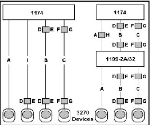
Use Figure 2-1 and the table on the following page to determine the typical maximum allowable cable distance between the Communications Server and an attached device. If your system has a multiplexer, you can install the maximum length of cable between the Communications Server and the multiplexer and again between the multiplexer and an attached device.
Additional information about cable types and distances is available in the following IBM Publications:
Using the IBM Cabling System with Communication Products, GA27-3620 IBM Cabling System Planning and Installation Guide, GA27-3361
IBM System/360 and System/370 I/O Interface Channel to Control Unit Original Equipment Manufacturers’ Information, GA22-6974
A Building Planning Guide for Communication Wiring, G320-8059
e d o
C CableMediaand/orConnector CableLength
A CoaxialCable 4920ft(1500m) B IBMType3specifiedMedia 100ft(30.5m)minimum
m u m i x a m ) m 5 7 2 ( t f 0 0 9
C IBMCablingSystemTypes1,2,and9
: 2 d n a 1 s e p y T ) m 0 0 5 1 ( t f 0 2 9 4 -s n u l a b 0 h t i W ) m 0 0 0 1 ( t f 0 8 2 3 -n u l a b 1 h t i W ) m 0 1 6 ( t f 0 0 0 2 -s n u l a b 2 h t i W ) m 0 0 0 1 ( t f 0 8 2 3 -s n u l a b 0 h t i W : 9 e p y T ) m 7 6 6 ( t f 6 8 1 2 -n u l a b 1 h t i W ) m 6 0 4 ( t f 3 3 3 1 -s n u l a b 2 h t i W
D 3270Coax-to-Twisted-PairAdapter 18ft(5.5m) E IBMDPCType3Connector 15ft(4.5m) F CoaxBalunAssemblyorCable-lessCoax
n u l a
B 8ft(2.4m)or16ft(4.9m) G DualPurposeConnectorAttachmentCable 8ft(2.4m)or30ft(9m)
H n i d e l l a t s n i A D F e v a h t s u m ( e l b a C c i t p O r e b i F , n o r c i m 5 2 1 / 5 . 2 6 ) r e v r e S s n o i t a c i n u m m o C n o r c i m 0 4 1 / 0 0 1 5 e p y T m e t s y S g n i l b a C M B I n o r c i m 5 2 1 / 0 5 r o ) m 0 0 5 1 ( t f 0 2 9 4
I TwistedWire(musthaveTWAinstalledin ) r e v r e S s n o i t a c i n u m m o C
When using fiber optic cable, a Fiber Optic Device Adapter must be installed in the Communications Server. Note that when using Type 3 media, a connector with a special actuator and filter (such as IBM’s DPC-T3) is required in order to connect devices equipped with a DPC. Otherwise, a Balun assembly is used.
The following limitations apply to the use of these devices: 1. (coax length) + (5 * twisted pair length) <= 4500 ft (1375 m) 2. (minimum twisted pair length) => 100 ft (30.5 m)
Power Cable Requirements
For units operating at 100-120V: The power cable required for domestic units is a UL listed, CSA certified, 18/3 AWG, type SJT, cable (15-foot [4.57-meter] maximum). It is terminated on one end by a 125V, 15A grounding type attachment plug. It is terminated at the other end by a 125V, 15A parallel blade, grounding type attachment plug.
For units operating at 200-240V: The power cable required for domestic units is a UL listed, CSA certified, 18/3 AWG, type SJT, cable (15-foot [4.57-meter] maximum). It is terminated on one end by a 250V, 15A grounding type attachment plug. It is terminated at the other end by a 250V, 15A tandem blade, grounding type attachment plug.
The installation site must provide a properly wired and grounded power outlet. Circuits connected to air conditioners and devices that generate significant transient electrical noise should be avoided.
Electrostatic discharge in the vicinity of the unit should be minimized by avoiding high resistance floor material and carpeting that does not have antistatic properties, avoiding the use of plastic seats and covers, and avoiding low humidity levels. The unit should be located away from areas that generate electromagnetic interference (for example, transformers, power distribution panels, and motors). The unit should not be installed where the atmosphere contains corrosive elements that may damage the unit.
Cable runs should avoid areas that produce electromagnetic interference (for example, near transformers, switching equipment, power distribution panels, and under carpets where vacuum cleaning is done). Also, heavy equipment should not be moved or rolled over the cable.
Connections
3270 Host Connection
Cable Types
On the SCC Board, for each 3270 host-to-control-unit line, you must use one of the following special Visara supplied cables:
e l b a
C PartNumbers
2 3 2 -S R A I E ) m 5 0 . 3 ( t f 0 1 -0 1 0 -8 2 1 1 1 2 ) m 1 . 6 ( t f 0 2 -0 2 0 -8 2 1 1 1 2 ) m 2 . 9 ( t f 0 3 -0 3 0 -8 2 1 1 1 2 ) m 2 . 2 1 ( t f 0 4 -0 4 0 -8 2 1 1 1 2 5 3 . V T T I C
C 211130-001
1 2 . X ) m 5 0 . 3 ( t f 0 1 -0 1 0 -1 5 4 6 0 2 ) m 1 . 6 ( t f 0 2 -0 2 0 -1 5 4 6 0 2 ) m 2 . 9 ( t f 0 3 -0 3 0 -1 5 4 6 0 2 ) m 2 . 2 1 ( t f 0 4 -0 4 0 -1 5 4 6 0 2
Caution: Failure to use specified cables may result in damage to the SCC board(s).
Token Ring Connection (TRC)
The Token Ring Interface cable can be attached directly to the Token Ring Media Access Unit (MAU), or can be extended by attaching it to another cable that is attached to the MAU. The Communications Server attachment point is at the TRC board using a 9-pin D connector.
Ethernet Connection (ETH) - 65S only (No longer offered)
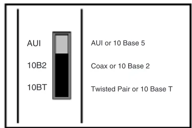
The Ethernet boards have three types of connections available: AUI (10 Base 5) using a 15-pin D connector, 50-ohm Coax (10 Base 2) using a BNC connector, or twisted pair (10 Base T) using RJ45 phone jack connector. Only one interface may be used at a time. A slide switch is used to select the interface for use (see Figure 2-3).
be connected to the BNC connector. End points of the coax cable must be terminated with a standard 50-ohm impedance. A standard Ethernet twisted pair cable can be connected to the RJ45 phone jack.
AUI 10B2 10BT
AUI or 10 Base 5
Coax or 10 Base 2
Twisted Pair or 10 Base T
Figure 2-3. Ethernet Interface Select Switch
10/100 Mbps Fast Ethernet (FET)
The single RJ-45 connector on the network cable supports 10 Mbps or 100Mps speeds. NWAY auto-negotiation enables the 10/100Mbps Ethernet NICs to automatically run at the speed that the connected hub supports. The 10/100Mbps Ethernet NICs works with products that comply with IEEE 10BASE-T and 100 BASE-TX specifications.
10BASE-T Operation
10BASE-T is the Institute of Electrical and Electronics Engineers (IEEE) 802.3 standard for Ethernet signaling over unshielded twisted-pair wire at 10 Mbps.
Ethernet, as the most widely used network protocol, uses 10BASE-T as its primary cabling scheme. Ethernet’s characteristics include:
• A data rate of 10 Mbps. • A broadcast architecture.
• A specific media-access control (MAC) scheme.
The 10BASE-T name indicates a signaling speed of 10 Mbps and twisted-pair wiring. Base stands for baseband, which denotes a technique for transmitting signals as direct-current pulses rather than modulating them onto separate carrier frequencies.
A wiring topology using 10BASE-T specifies a wiring hub, cable arranged in a star configuration, and unshielded twisted-pair cable. Each node has a separate cable run that must not exceed 100 meters (328 ft) from the node to the hub.
100BASE-TX Operation
100BASE-TX is the IEEE 802.3u standard for Fast Ethernet signaling over Category 5 UTP or STP wire at 100 Mbps.
Based on an extension to the IEEE 802.3 Ethernet specification, Fast Ethernet’s characteristics include:
• A data rate of 100 Mbps. • A broadcast architecture.
A wiring topology using 100BASE-TX specifies a wiring hub, cable arranged in a star configuration, and Category 5 UTP or STP wiring. Each node has a separate cable run that must not exceed 100 meters (328 ft) from the node to the hub.
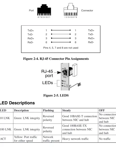
Figure 2-4 shows the RJ-45 connector pin assignments for the 10/100 Mbps Ethernet NIC.
Port Connector
8 7 6 5 4 3 2 1 1 2 3 4 5 6 7 8
TxD+ TxD-RxD+ RxD-1 2 3 6 1 2 3 6 TxD+ TxD-RxD+ RxD-Pins 4, 5, 7 and 8 are not used
Figure 2-4. RJ-45 Connector Pin Assignments
Figure 2-5. LEDS
LED Descriptions
D E
L Description Flashing Steady OFF
K N L 0
1 Green:LNKintegrity Reversed y t i r a l o p n o i t c e n n o c T -E S A B 0 1 d o o G b u h d n a C I N n e e w t e b n o i t c e n n o c o N C I N n e e w t e b b u h d n a K N L 0 0
1 Green:LNKintegrity Reversed y t i r a l o p X T -E S A B 0 0 1 d o o G C I N n e e w t e b n o i t c e n n o c b u h d n a n o i t c e n n o c o N C I N n e e w t e b b u h d n a T C
A Yellow:Porttraffic d e e p s r e h t i e r o f k r o w t e N t n e s e r p c i f f a r
ASCII Host/Device Cabling (65S only)
Use a 25 pin RS-232 connector to attach ASCII hosts and/or devices to the receptacles on the back of the 1174 Communications Server. The ASCII feature requires a male connector on the cable to mate properly.
It is recommended that you use one of the following ASCII cables for each host and/or device. Customer provided cabling is also acceptable. Customer is responsible for the correct wiring of customer provided cables.
r e b m u N t r a
P Description
0 1 0 -5 5 0 2 1
2 Modemcablewithmaleconnectoratthedeviceend(10ft[3.05m]) 0 2 0 -5 5 0 2 1
2 Modemcablewithmaleconnectoratthedeviceend(20ft[6.1m]) 0 3 0 -5 5 0 2 1
2 Modemcablewithmaleconnectoratthedeviceend(30ft[9.2m]) 0 4 0 -5 5 0 2 1
2 Modemcablewithmaleconnectoratthedeviceend(40ft[12.2m]) 0 1 1 -5 5 0 2 1
2 Nullmodemcablewithmaleconnectoratthedeviceend(10ft[3.05m]) 0 2 1 -5 5 0 2 1
2 Nullmodemcablewithmaleconnectoratthedeviceend(20ft[6.1m]) 0 3 1 -5 5 0 2 1
2 Nullmodemcablewithmaleconnectoratthedeviceend(30ft[9.2m]) 0 4 1 -5 5 0 2 1
2 Nullmodemcablewithmaleconnectoratthedeviceend(40ft[12.2m]) 0 1 2 -5 5 0 2 1
2 Nullmodemcablewithfemaleconnectoratthedeviceend(10ft[3.05m]) 0 2 2 -5 5 0 2 1
2 Nullmodemcablewithfemaleconnectoratthedeviceend(20ft[6.1m]) 0 3 2 -5 5 0 2 1
2 Nullmodemcablewithfemaleconnectoratthedeviceend(30ft[9.2m]) 0 4 2 -5 5 0 2 1
2 Nullmodemcablewithfemaleconnectoratthedeviceend(40ft[12.2m])
: y l n o t n e m h c a t t a 0 2 3 T V C E D r o F 0 1 3 -5 5 0 2 1
2 Nullmodemcablewithfemaleconnectoratthedeviceend(10ft[3.05m]) 0 2 3 -5 5 0 2 1
2 Nullmodemcablewithfemaleconnectoratthedeviceend(20ft[6.1m]) 0 3 3 -5 5 0 2 1
2 Nullmodemcablewithfemaleconnectoratthedeviceend(30ft[9.2m]) 0 4 3 -5 5 0 2 1
2 Nullmodemcablewithfemaleconnectoratthedeviceend(40ft[12.2m])
: s e t o N .
1 AttachingaDECVT320toanASCIIcablerequiresanadapter.SeetheDEC . n o i t a m r o f n i e r o m r o f l a u n a m s ’ r o t a r e p o s ’ 0 2 3 T V .
2 MaximumrecommendedlengthsforASCIIhostanddevicecablesvaryby h t i w k c e h c , s e l b a c d e i l p p u s y n a p m o C e s u t o n o d u o y f I . r e r u t c a f u n a m e l b a c . n o i t a m r o f n i h t g n e l m u m i x a m r o f r e r u t c a f u n a m e h t
Coax Device Attachment
Dynamic Multiplexing
Dynamic Multiplexing (see the Configuration and Central Control manuals) supports: • 1199-type multiplexers (or direct device connections) on the following physical ports:
• 1174-65S, Coax Device Adapter (CDA) board ports labeled 0 - 7 (maximum 2 boards) • 1174-90S, Ports 0 - 8.
• Configuration of 1 - 8 devices on each multiplexer.
If you are using Dynamic Multiplexing, you must enable the feature during configuration and assign port addresses on the Coax Port and Mux Assignments panel described in the
Configuration and Central Control manuals.
If you are not using Dynamic Multiplexing, refer to the following for information about coax port addresses.
1174-65S Device Attachment
Coax devices are attached to the Coax Device Adapter (CDA) board(s) on the back of the Communications Server.
ASCII devices are attached to the ASCII Device Adapter (ADA) board(s) on the back of the Communications Server.
Dynamic Multiplexing
If Dynamic Multiplexing is to be used in your network, you can change logical port assignments by completing the Dynamic Multiplexing Assignments panel described in the Configuration manual.
Without Dynamic Multiplexing, the 1174-65S may have one or two 18-port CDAs or a 9-port CDA.
18-Port CDA Board Connections (65S only)
Figure 2-6 shows an 1174-65S with two 18-port CDA boards. They are referred to as the left and right CDAs.
Figure 2-6. 1174-65S Coax Ports (Two 18-Port Boards)
The right CDA allows direct attachment to Ports 0 through 15. Ports 0 and 8 permit attachment directly to coax devices or attachment to a multiplexer. Ports 16 and 24 permit attachment only to a multiplexer.
9-Port CDA Board Connections
Figure 2-7 illustrates a 9-port CDA board. Ports 0 through 8 support direct attachment of coax devices. Ports 0 and 8 also support attachment to a multiplexer.
Figure 2-7. 1174-65S Coax and ASCII Ports (9-Port CDA)
Assigning Logical Ports
Logical ports are assigned in groups of eight devices. These groups are ports: • 0 through 7
• 8 through 15
• 16 through 23 (not available on 9-port CDA) • 24 through 31 (not available on 9-port CDA)
Fiber Optic Device Adapter (FOA) Board (65S only) (No longer offered)
The Fiber Optic Device Adapter (FOA) board is an option that allows the use of fiber optic cabling as the communication link between the 1174 Communications Server and multiplexer. The FOA converts the multiplexed output from the 1174-65S to fiber optic signals. The fiber optic cable can then be attached to a multiplexer device with fiber optic capability such as the 1199-32 Multiplexer. The FOA occupies Slot J3 (the right-most CDA slot, rear view) in the 1174-65S Communications Server. The FOA board provides a single BNC connector for configuring the unit prior to attaching the fiber cable to a multiplexer.
The fiber optic cable is connected to the ST type connectors labeled (transmit signal to the multiplexer) and (receive signal from the multiplexer). Two yellow LEDs labeled (transmit) and (receive) indicate communication between the Communications Server and attached multiplexer.
1174-90S Device Attachment
Coax devices are attached to the Coax Device Adapter (CDA) board(s) on the back of the Communications Server.
Dynamic Multiplexing
If Dynamic Multiplexing is to be used in your network, you can change logical port assignments by completing the Dynamic Multiplexing Assignments panel described in the
Configuration manual.
9-Port CDA Board Connections
Figure 2-8 illustrates a 9-port CDA board. Ports 0 through 8 support direct attachment of coax devices. Ports 0 and 8 also support attachment to a multiplexer.
Figure 2-8. 1174-90S Coax Ports (9-Port CDA)
Assigning Logical Ports
Logical ports are assigned in groups of eight devices. These groups are ports: • 0 through 7
• 8 through 15
High Speed Communication Interface (65S only)
The High Speed Communications (HSC) board provides a high speed remote communications interface to SDLC and Frame Relay Networks. Each HSC board provides up to four high speed channels.
Cabling
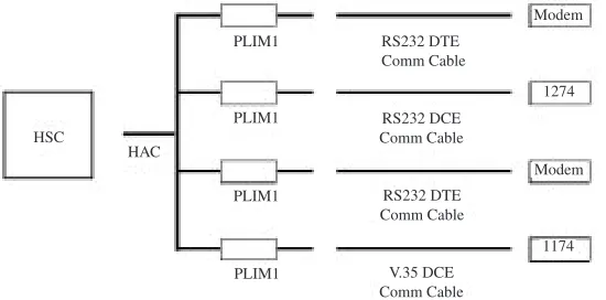
The HSC feature includes an HSC Adapter Cable (HAC). One end attaches to the HSC board, the other end splits into four connectors. Each connector provides a communication line capable of operating at full-duplex speeds of up to 8 Mbps.
The physical layer interface type is selected using a physical layer interface module (PLIM) and one of four HSC communication cables. The PLIM1 supports either RS232 or V.35 communication protocol, PLIM2 supports X.21 protocol. The type cable used determines the protocol type. Any combination of PLIMs and/or cables may be connected to the HSC board.
s e l b a C
0 2 0 -1 1 7 8 6
9 RS232 DTE 0
2 0 -2 1 7 8 6
9 RS232 DCE 0
2 0 -3 1 7 8 6
9 V.35 DTE 0
2 0 -4 1 7 8 6
9 V.35 DCE 0
2 0 -5 1 7 8 6
9 X.21 DTE
Note: The cable assemblies supplied for use with the HSC board and PLIMs are Visara
The DCE cables allow direct connection to DTE devices; no modem or modem eliminator is required. When a DCE interface is selected, the HSC should be configured to generate the transmit clock. Baud rates up to 1 Mbps are supported and configured on the HSC line panels.
HSC
HAC
PLIM1
PLIM1
PLIM1
PLIM1
RS232 DTE Comm Cable
V.35 DCE Comm Cable
RS232 DTE Comm Cable RS232 DCE Comm Cable
Modem
Modem 1274
1174
Figure 2-9. Sample HSC Installation
RS232 Serial Interface
Serial Port
A serial port is provided with the FET and VHP cards. The serial port on the VHP card is not functional. The serial communications port on the FET provides a full-duplex asynchronous/ synchronous receiver and transmitter. The port is used for serial communications. The serial port setting for baud rate, data bits and stop bits are set via a configuration panel.
Control (CTRL) Connector Pinouts
n i
P Signal Comment I/O
1 DCD ReceivedLineSignalDetector )
t c e t e D r e i r r a C a t a D
( I
2 RxD ReceivedData I 3 TxD TransmitData O 4 DTR DataTerminalReady O 5 GND SignalGround NA 6 DSR DataSetReady I 7 RTS RequestToSend O 8 CTS ClearToSend I 9 RI RingIndicator I
Serial Port Signal Definitions
The electrical specifications of the serial port are contained in the EIA (Electronics Industry Association) RS232C standard. For more information please consult the EIA RS232-C standard.
The following paragraphs contain a brief description of some of the serial port signals.
Transmitter Serial Data Output (TxD)
Serial Data Output.
Receiver Serial Data Input (RxD)
Clear-To-Send (CTS)
This line indicates that the Modem is ready to exchange data.
Request-To-Send (RTS)
This line informs the Modem that the Serial Interface is ready to exchange data.
Data Carrier Detect (DCD)
When the modem detects a “Carrier” from the modem at the other end of the phone line, this Line becomes active.
Ring Indicator (RI)
Goes active when modem detects a ringing signal. This signal tells the Serial Interface that a phone line is “ringing”. i.e. there is an incoming call.
Data Set Ready (DSR)
This tells the Serial Interface that the modem is ready to establish a link.
Data Terminal Ready (DTR)
Introduction
This chapter presents 1174 Communications Server board placement information to provide optimum performance. Information includes board names, identification (ID) descriptions, and slot population information.
Printed Circuit Board Names
The following lists the names for all the printed circuit boards that can be used in 1174 Communications Servers. Some of the boards are optional, and some can be used only in specific 1174 models. The printed circuit boards are typically referred to by their abbreviated names.
P C
A ASCIIConnectorPanel FOA FiberOpticDeviceAdapter )
5 6 / 5 2 -4 7 1 1 (
A D
A ASCIIDeviceAdapter FET FastEthernetNIC
C I
A ASCIIInterfaceController HPP HighPerformanceProcessor
A D
C CoaxDeviceAdapter HSC HighSpeedCommunication
C T
E TokenRing/EthernetController SCC(1R) SerialCommunicationsController )
5 3 . V / 2 3 2 -S R (
H T
E Ethernet TRCII TokenRingController
A D
F FiberOpticDeviceAdapter(1174-15) VHP VeryHighSpeedProcessor
Board Types Used
The following shows the types and names of printed circuit boards that may used in different models of the 1174.
e p y
T 1174-65S 1174-90S
r o s s e c o r
P SCP* P P H
P H V
* P C S
P P H
P H V r
e l l o r t n o C O /
I AIC * C C M
I I C R T
) R 1 ( C C S
H T E
C S H
T E F
* C C M
I I C R T
) R 1 ( C C S
T E F
y r o m e
M MEM* MEM* t
n e m h c a t t A e c i v e
D CDA A O F
A D A
A D C
s u o e n a l l e c s i
M OperatorPanel OperatorPanel
Slot Population
Many of the printed circuit boards for the Communications Server are located in partitions called slots, which are identified with numbers.
Use the following charts to determine the slot(s) in each Communications Server model into which these boards may be installed. Dependent upon configuration parameters, circuit boards may only occupy certain physical slots. Some errors occur because of incorrect slot population.
1174-65S
Slot population for the 1174-65S allows most boards to be installed in more than one available slot. Presented herein are slot choices, which the circuit boards may occupy.
d r a o
B firstslotchoice1throughlastslotchoice5
1 2 3 4 5
C C
S 4 5 6
P P
H 7 5 6 9 8
I I C R
T 4 5 6
C S
H 4 5 6
C I
A 9
T E F / H T
E 4 5 6
P H
V 4 5 6
*Slots 10, 13, and 16 are logical assigned slots for the board circuitry identified. There are no physical connectors. The circuitry is located on the Mother board. The FOA can only be installed in the rightmost CDA slot as viewed from the rear.
1174-90S
Slot population for the 1174-90S allows most boards to be installed in any available slot.
Presented herein are slot choices, which the circuit boards may occupy.
d r a o
B firstslotchoice1throughlastslotchoice5
1 2 3 4 5
C C
S 4 5 6
I I C R
T 4 5 6
T E
F 4 5 6
Slot Identification
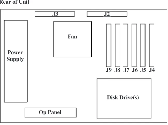
Many of the printed circuit boards for the Communications Servers are located in partitions called slots, which are identified with numbers. These slots are sometimes specified by error messages that permit the easy identification of a failing or incorrectly placed PCB. Figure 3-1 shows the locations of the 1174-65S/90S PCB physical slots.
Rear of Unit
Power Supply
Fan
Op Panel
J3 J2
Disk Drive(s) J9 J8 J7 J6 J5 J4
Figure 3-1. 1174-65S/90S Printed Circuit Board Slots
Slot Numbers
The following chart presents the physical J number slots used in the JSS member of failure messages.
S 5 6 -4 7 1
1 1174-90S
t o l
S Description Slot Description
9 0 -4
0 Mainboardexpansionslots 04-09 MainboardSCC 0
1 MainboardRAM 10 MainboardRAM 3
1 MainboardMCC 13 MainboardMCC 6
1 MainboardSCP 16 MainboardSCP 1
3 HardDisk 34 Floppydisk1 4
3 Floppydisk1 35 Floppydisk2 5
Logical Identifiers
Either their physical locations (J number) or their logical identifiers (ID) may identify the Communications Server board slots. These numbers are used in identifying boards that failed. The following is a cross reference list between the board slot J numbers and the board slot logical IDs.
S 0 9 / S 5 6 -4 7 1 1 #
J SlotID J# SlotID J# SlotID
) 6 1
( 0D 04 00 07 03 )
3 1
( 0A 05 05 08 02 )
0 1
( 07 06 04 09 09
Note: Slots designated within parentheses ( ) have no physical connectors. These logically
assigned slots with circuitry are located on the Mother board.
Board ID Assignments
The board ID is used in error determination. Each board type or circuit function has a particular identification number assigned. The board IDs have a general format of a 5-bit board type identifier and a 3-bit revision level indicator. To display the 3-bit revision level, execute Utility 16 or Utility 28. The format is as follows:
7 6 5 4 3 2 1 0
ID Rev
---The following lists the board identification and board name/type.
D
I Rev BoardName
0
0 (Noboardinstalled) 0
1 5 SCP(65Sonly) 0
3 SCC 8
3 HSC 0
4 MCCII 8
4 0 CDA 0
5 AIC 8
6 FET 0
7 0 TRCII 8
7 VHP 8
A 2-,4-,or6-MbRAM 8
F MBR,MainboardRAM 0
0
1 FloppyDriveA 0
1
1 FloppyDriveB 0
2
1 HardDriveC(65Sonly) 0
4
1 OperatorPanel 0
5
1 OPLII 0
6
1 ADA(65Sonly) 0
0
Indicators
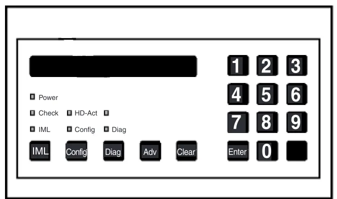
Operator Panel LEDs
Located on the operator panel are LEDs that indicate some of the operational states of the Communications Server. LEDs that may be found on the operator panel include the following:
Diag - Lights when the Communications Server is in Extended Diagnostics mode. Customer
service representatives use this mode.
Config - Lights when the 1174 is IMLed onto the default configuration. It will remain on
until the Communications Server is IMLed onto a saved configuration.
IML - Lights while the Communications Server is executing Basic Assurance tests and loading
its operating program. When the IML light goes off, the operating program is loaded and the Communications Server is ready for service.
Check - Lights when an error or failure has occurred that requires corrective action. Power - Lights to indicate that the Communications Server is powered on and that +5 volts
are present.
HD-Act - Lights to indicate hard disk drive activity (if installed). Off-line Indicator - Serves no purpose on the 1174-65S or 1174-90S.
Power
Check
IML
HD-Act
Config Diag
IML Config Diag Adv Clear
1
2
3
4
5
7
8
9
0
6
Enter
Figure 4-1. Operator Panel
High Speed Communication Interface
Controls
Power Switch
The 1174-65S/90S Communications Server Power switch is located near the front lower left corner of the unit. Set the switch to the On ( | ) position to turn on power, and set the switch to the Off (O) position to turn off power..
Keypad
Config - When IML 500 appears on the display after the 1174 is powered on or the IML key
is pressed, press the Config key to IML into the default configuration only. The Configuration and Central Control manuals contain information about the Configuration mode.
Diag - Initiates the diagnostics facility.
Adv - The Adv (Advance) key advances the operator panel display while online or during
error conditions.
Clear - Erases previously entered data, provided that the Enter key has not been pressed in
diagnostic mode. Pressing the clear key at State 500 of IML initiates the software merge utility.
Numbers 0 through 9 - Used to enter parameters and perform other data entry functions. Enter - Used to enter data. Press the Enter key after pressing a string of keys that represent
parameters. When pressed at State 500 of IML, it allows entering of additional commands.
Alt - Used to initiate basic assurance tests when pressed at IML State 500.
IML - Pressing IML (Initial Machine Load) causes the Communications Server to perform
a complete reload of software from disk.
The following are valid when IML 500 is displayed:
Adv - Continue IML with System Microcode. No extended BATs are executed. If an alternate
drive and state have been entered (Enter options), then the specified System Microcode is loaded. Otherwise, the System Microcode in production on the first hard disk containing a System Disk subdirectory is loaded.
Alt, Adv - Same as Adv, but execute extended BATs during IML. Diag - Enter Diagnostics mode.
Config - Load default Customization Data Objects instead of those defined on the System
subdirectory allowing the Communications Server to IML with default customization parameters. This also loads the default configuration allowing entering the Configuration utility without entering a password.
Alt, Config - Same as Config, but execute extended BATs during IML.
Clear - Clear the System Microcode currently on hard disk and load a new System Microcode
from floppy diskette.
IML Procedure for 90S and 65S
The following describes the procedure to IML the 90S Communications Server using LINCS software. Install “LINCS System 1” diskette in drive A and “LINCS System 2” diskette in drive B, then power on or press IML.
The “mode prompt” appears on the LCD at state 500: IML 500 M=
At this state, the LINCS node will pause for five seconds waiting for input from the operator keypad illustrated below. If nothing is specified within five seconds, the standard IML will proceed.
• ADV – Continue IML with system microcode. No extended BATs are executed. • ALT, ADV – Same as ADV, but executes extended BATs during IML.
• DIAG – Enters Diagnostics mode.
• CONFIG – Loads default customization data objects instead of the ones defined in the system subdirectory. This option is useful when a problem with the customization data affects the operation of the LINCS node. This option allows IML with default customization parameters without affecting the ones defined in the system subdirectory. Loading the default configuration also allows you to enter the Configuration utility without entering a password. Once the default customization data objects have been loaded and the LINCS node has IMLed, the data objects may be modified as desired. • ALT, CONFIG – Same as CONFIG, but executes extended BATs during IML.
Please refer to Visara’s LINCS Problem Determination manual (P/N 707022-001) for an explanation of LINCS messages.
Additional IML Options for 65S
The following describes changing the normal IML parameters. 1. Perform a power-on IML. At IML State 500, press the Enter key.
2. Prompts will be displayed for entry of drive from which to IML, level of software, and mode of operation for IML state. The table on the following page describes the parameter entries allowed. r e t e m a r a
P Description
d SelectsdiskdrivefromwhichtoIML(A=1,B=2,C=3,D=4).
l . L M I o t h c i h w m o r f ) e t a t s r o l e v e l ( e r a w t f o s s t c e l e S n o i t c u d o r P -1 l e v e l k c a B -2 l a i r T -3 y l n o , d e s u g n i e b t o n s i t n e m e g a n a M e g n a h C e t i S l a r t n e C f I . s k s i d e h t n o t n e s e r p s i e r a w t f o s l e v e l n o i t c u d o r p m . L M I r o f n o i t a r e p o f o e d o m s t c e l e S . ) T A B g n i s s a p y b L M I l a m r o n ( l a m r o N = v d A . ) e d o m n o i t a r u g i f n o C o t n i L M I ( g i f n o C = g i f n o C . ) e d o m s c i t s o n g a i D o t n i L M I ( g a i D = g a i D
3. The third prompt is IML 50X M=_, where X is the drive selected. Enter the type of IML mode. 4. Allow IML to complete.
Error Types
This chapter describes the types of errors and failures that can occur while the Communications Server is operating.
There are four main types of errors or failures: • IML errors
• Exception errors • Hardware failures • Online errors
Indicators that tell you that one of the above conditions has occurred are some or all of the following:
• Error log
• Status line of attached terminal • Operator panel display
• Operator panel check light • Printed circuit board LEDs
IML Errors (ERR ___)
Initial Machine Load (IML) occurs when the 1174 is turned on or when the IML key on the operator panel is pressed. During IML, the Communications Server executes a series of tests that checks the machine’s ability to operate.
An IML error message looks like this on the operator panel:
ERR XXX*
where: ERR indicates the occurrence of an IML error.
XXX is the IML state in which the error occurred.
* indicates that additional messages are available that describe the error (not always present).
IML errors and possible recovery are described in Problem Determination.
Exception Errors (XCP ___)
Exception errors are detected by a processor and occur during IML. Exception errors are nonrecoverable and require recording the error information and then IMLing the Communications Server to resume operation.
Exception error messages look like this on the operator panel:
where: XCP indicates an exception error.
JSS indicates the physical slot number of the board where the error occurred. BB shows the board ID in hexadecimal format.
EEE shows the type of exception error.
* indicates additional messages that give more information about the error (not always present).
Problem Determination contains additional information about Exception errors.
If unable to correct the problem, prepare a dump disk of the error information, Problem Determination “Utility 20” and then call the next level of technical support.
Hardware Failures (FAIL ___)
Hardware failures show specific hardware problems. They may occur during IML or testing mode. Code verification errors may also display as a hardware failure.
Error messages display on the operator panel as shown below:
Hardware - FAIL JSS:BB:TNN*
Code Verification - FAIL JSS:BB:MOV*
where: FAIL indicates a hardware error.
JSS is the slot number of the failing board.
BB shows the board type ID in hexadecimal format. T is the failing test type.
NN is the failing test number.
MOV indicates that the diagnostic code a processor board moved to its local memory does
not match the code from where it was moved.
* indicates additional messages that give more information about the error.
Problem Determination, Hardware Failures, and Off-line Testing, contain additional
information about Hardware failures.
Online Errors
Online errors show problems that occur while the Communications Server is online with its host and attached devices. Online error numbers may appear on the operator panel (some 300- and 500-type errors only), preceded by an indication of which attached host system is involved, and may be displayed on an attached display’s status line preceded by X. Problem
Error Indicators
Event Log
The Communications Server’s Event Log records the Online errors as well as many other useful events described in Problem Determination, Error Log.
Status Line of Attached Terminal
The status line of attached terminals shows many of the Online errors and conditions that occur. Problem Determination contains additional information about Online errors.
Operator Panel Display
The 16-character operator panel LCD display indicates a wide variety of Communications Server states and errors. The operator panel LCD display shows all error conditions except:
• An error occurring in IML before the operator panel is initialized. • Certain Online errors.
Operator Panel Check Light
The operator panel Check Light is located on the operator panel. When it is lit, an error or failure has occurred that requires corrective action.
Software Merge (65S only)
This procedure is used to install a new software level onto the 65S. 1. IML the unit.
2. At “IML 500 M=” press the Clr key.
3. At the “Merge s: to d:” prompt (where s=source and d=destination drive), press the Enter key to proceed with the software merge.
Note: To abort the merge procedure, press the IML key. The merge procedure will overwrite
existing microcode files of the same name, so it is not recommended to press IML once the merge has started.
7. At the “Insert s:SYSn” prompt, insert the requested system diskette (by number n) in the source drive, close the drive door, then press the Enter key. A progress message “nn% Complete” is displayed while files are being copied.
During the software merge, warning and failure messages may be displayed indicating problems during the merge.
Warning Messages
e g a s s e
M Description
k s i D g n o r
W Thedisketteinsertedintothesourcedriveisnottherequestedsystemsdisk.Press .
e g a s s e m k s i D t r e s n I e h t o t n r u t e r o t y e k r e t n E e h t l e v e L g n o r
W Thedisketteinsertedintothesourcedriveisnotofthesamelevelastheprevious . e g a s s e m k s i D t r e s n I e h t o t n r u t e r o t y e k r e t n E e h t s s e r P . s e t t e k s i d s m e t s y s
Failure Messages
e g a s s e
M Description
y p p o l F L I A
F Themergerequiresafloppydriveasthesource. d
r a H L I A
F Themergerequiresaharddriveasthedestination. B
-n e G L I A
F ThemergewillnotcopysoftwaretoaharddrivethathasGen-Bsoftwareonit. e
e : x k s i D L I A
Replacement
Introduction
This chapter presents procedures used by service representatives to remove and replace assemblies that may be installed in the Communications Server.
Prior to any removal or replacement procedure, make sure the Communications Server is turned OFF and the power cord is disconnected from the AC wall outlet.
1174-65S/90S
Prior to any removal or replacement procedure, make sure the Communications Server is turned OFF and the power cord is disconnected from the AC wall outlet. Ensure all cabling is properly identified and marked before proceeding with any removal procedures.
Replaceable Assemblies
n o i t p i r c s e
D VisaraP/N Description VisaraP/N
) y l n o S 5 6 ( A D
A 210561-900/941 HSC(65Sonly) 220265-906 )
y l n o S 5 6 ( C I
A 210560-001/041 HSCAdapterCable )
y l n o S 5 6
( 220210-001 )
y l n o S 5 6 ( t r o P -8 1 , A D
C 210557-912/952 MotherBoard 220224-200/240 t
r o P -9 , A D
C 210557-911/951 OperatorPanel 211700-001 H
T
E 213430-906/946 PLIM1(65Sonly) 968707-001 T
E
F 220273-906 PLIM2(65Sonly) 968708-001 e
l b a C k s i D y p p o l
F 206467-003 PowerSupply 210652-001 e
v i r D k s i D y p p o l
F 205140-002 SCC(RS-232/V.35) 210555-906 )
y l n o S 5 6 ( e v i r D k s i D d r a
H 210674-004 TRCII,16/4Mb/s(GenC) 206617-906 l
a n g i S , e l b a C D D H
) y l n o S 5 6
( 206421-002 VHP 220271-906 P
P
H 206614-906
Note: Part numbers listed following “/” indicate the assembly with packaging.
Covers
The back plate and main covers must be removed to gain internal access to the 1174-65S.
Removal
1. Ensure power is off.
2. Mark all cables properly for reinstallation before removing covers. 3. Remove all cables from the back of the unit.
4. Remove screws attaching the rear panel metal cover. Remove the rear panel cover. 5. Remove the four screws attaching the main cover to the unit chassis.
6. Slide the main cover toward the front of the unit to remove it from the chassis.
Replacement
1. Reverse the procedure to replace the covers. 2. Reattach all cables to the proper connectors.
Circuit Board Assembly
Each Circuit board assembly is held in place by captive fastening screws located at the top of the rear guide bracket.
Removal
1. Ensure power is off. Remove the main cover.
2. Locate the Circuit board to be removed. For board slots J04-J09, loosen the fastening screws holding the front board guide racket in place. Slide the bracket clear of the boards. 3. Loosen the captive screw attaching the board to the rear bracket (CDA boards have two
captive screws).
Replacement
1. Locate the correct slot the Circuit board is to be located.
2. Align the Circuit board onto its mounting track and slide the board into place. Ensure the board connector is properly seated.
3. Tighten the fastening screw to the board bracket. If loosened, realign and tighten the front board guide bracket.
4. Replace the covers and cables.
Power Supply Assembly
The Power Supply assembly is held in place by three screws.
Removal
1. Ensure power is off. Remove the cover.
2. Remove the screws holding the assembly in place. One is located at the front bracket, one is located near the leftmost CDA board attaching the ground screw to the chassis, and the third is located near the middle of the assembly.
3. Locate and disconnect all cables attached to the Power Supply Cable assembly. 4. Lift the assembly from its mounting.
Replacement
1. Align the assembly onto its mounting place. 2. Install the fastening screws.
3. Connect all cables to the assembly and replace the cover.
Operator Panel
The operator panel is attached to the Communications Server with plastic guides.
Removal
1. Ensure power is off. Remove the covers. 2. Disconnect the operator panel cable. 3. Lift the panel clear of its mounting bracket.
Replacement
1. Align the assembly guideposts into place on the mounting bracket. 2. Press the operator panel into place.
Floppy Disk Drive
The following procedure describes removing the 3.5-inch diskette drive.
Removal
1. Ensure power is off. Remove the covers.
2. Locate and disconnect the drive control and power supply cables.
3. Remove the four screws attaching the disk drive to its bracket. There are two screws located on each side of the drive bracket.
4. Carefully slide the drive from its bracket.
Replacement
1. Align the disk drive into its mounting track. 2. Carefully slide the disk drive into its bracket. 3. Install the screws to attach the drive to the bracket. 4. Connect the drive control and power supply cables. 5. Replace the covers.
Hard Disk Drive (65S only)
The hard disk drive with bracket is installed in the lower floppy drive bay. The following procedure describes removing the hard disk drive.
Removal
1. Ensure power is off. Remove the covers.
2. Locate and disconnect the drive control, fan, and power supply cables.
3. Remove the four screws attaching the disk drive to its bracket. There are two screws located on each side of the drive bracket.
4. Carefully slide the drive from its bracket.
Replacement
1. Align the disk drive into its mounting track. 2. Carefully slide the disk drive into its bracket. 3. Install the screws to attach the drive to the bracket.
4. Connect the drive control and power supply cables and DC fan power cable.
Note: Ensure the drive control cable is properly attached to J12 on the Mother
board.
5. Replace the covers.
Memory Module
Local and Common memory upgrades are installed on the Mother board by using custom memory modules.
1. Ensure power is off and power cord unplugged from the AC source. 2. Remove the top cover to gain access to the Mother Board.
3. Install/replace memory module upgrades as shown below. Local Memory is located at U3, U10, and U18.
Common Memory is located at U6, U11, and U19. A memory control module (U21) must also be replaced with upgrades of common memory.
4. Execute Utility 57 to reconfigure memory installed . DO NOT CONFUSE THIS WITH THE AMOUNT OF COMMON MEMORY INSTALLED! The utility is password protected. When prompted, enter the amount of memory installed. 5. When replacing the memory control module (U21), execute Utility 56 to configure
number of floppy drives installed.
Mother Board Assembly
Removal
1. Ensure power is off. Remove the covers.
2. Remove all Circuit boards attached to the board guide from the unit. 3. Disconnect all cables attached to the Mother board.
4. Remove the nine screws attaching the main plate to the chassis. There are three screws on each side and three on the back.
5. Carefully lift the main plate from the chassis.
Note: The power supply, operator panel, and disk drives are attached to the main
plate.
5. Remove the five mounting screws attaching the Mother board to the chassis. 6. Lift the Mother board clear of its mounting.
Replacement
1. Reverse the procedure to install the Mother board.
D
Device Attachment, 11 Diag, 21
Dynamic Multiplexing, 10
E
EIA and X.21, 4
Environmental Parameters, 4 Error Indicators, 26
Error Types, 24 ETH, 1
Ethernet Connection (ETH) - 65S only, 7 Event Log, 26
Exception Errors, 24
F
Failure Messages, 27 FET, 2
Fiber Optic Cable, 5
Fiber Optic Device Adapter (FOA) Board (65S only), 12
Floppy Disk Drive, Removal, 32 FOA, 1
H
Hard Disk Drive, Removal, 32 Hardware Failures, 25 HD-Act, 21
High Speed Communication Interface, 13 HPP, 1
HSC, 1
I
IML, 21 IML Errors, 24 IML Options, 23 IML Procedure, 23 Indicators, 21
Installation Checklist, 3
Installing/Removing Circuit Boards, 3
K
Keypad, 22
Symbols
1174-65S Hardware Components ADA, 1
AIC, 1 CDA, 1 ETH, 1 FET, 2 FOA, 1 HPP, 1 HSC, 1 MEM, 1 SCC, 1 SCP, 2 SHA, 1 TRC II, 2 VHP, 2 1174-90S
Device Attachment, 12 Hardware Components, 2
18-Port CDA Board Connections, 11 3270 Host Connection, 7
9-Port CDA Board Connections, 12
A
ADA, 1 AIC, 1
ASCII Host/Device Cables, 5 ASCII Host/Device Cabling, 10 Assembly Drawing, 29
Assembly Removal/Replacement, 29
B
Board ID Assignments, 20 Board Population, 17 Board Types Used, 17
C
CDA, 1 Check, 21
Circuit Board, Removal, 30 Coax Device Attachment, 10 Coax Device Cables, 5
Types and Lengths, 5 Config, 21
L
LED Descriptions, 9
Location Planning for the 1174, 4 Logical Identifiers, 20
M
Maximum Cable Distance, 4 ASCII Host/Device Cables, 5 Coax Device Cables, 5 EIA and X.21, 4 Fiber Optic Cable, 5 Power Cable, 4 Token Ring Cable, 5 V.35 Cable, 4 MEM, 1 Memory Module
Upgrades, 33
Mother Board, Removal, 33
O
Online Errors, 25
Operator Panel Display, 26 Operator Panel LEDs, 21
Check, 21 Config, 21 Diag, 21 HD-Act, 21 IML, 21
Off-line Indicator, 21 Power, 21
Operator Panel, Removal, 31
P
Power, 21 Power Cable, 4
Power Cable Requirements, 6 Power Requirements, 4 Power Supply, Removal, 31 Power Switch, 22
Printed Circuit Board Names, 17 Printed Circuit Boards, 3
R
Replaceable Assemblies, 30 RS232 Serial Interface, 14
S
SCC, 1 SCP, 2 Serial Port, 14 SHA, 1
Slot Identification, 19 Slot Numbers, 19 Slot Population, 18 Software Merge, 26
T
Token Ring Cable, 5
Token Ring Connection (TRC), 7 TRC II, 2
U
Unpacking Printed Circuit Boards (PCBs), 3
V
V.35 Cable, 4 VHP, 2
W