s o l u t i o n s @ s y n g r e s s . c o m
With more than 1,500,000 copies of our MCSE, MCSD, CompTIA, and Cisco study guides in print, we continue to look for ways we can better serve the information needs of our readers. One way we do that is by listening.
Readers like yourself have been telling us they want an Internet-based ser-vice that would extend and enhance the value of our books. Based on reader feedback and our own strategic plan, we have created a Web site that we hope will exceed your expectations.
[email protected] is an interactive treasure trove of useful infor-mation focusing on our book topics and related technologies. The site offers the following features:
■ One-year warranty against content obsolescence due to vendor
product upgrades. You can access online updates for any affected chapters.
■ “Ask the Author” customer query forms that enable you to post
questions to our authors and editors.
■ Exclusive monthly mailings in which our experts provide answers to
reader queries and clear explanations of complex material.
■ Regularly updated links to sites specially selected by our editors for
readers desiring additional reliable information on key topics.
Best of all, the book you’re now holding is your key to this amazing site. Just go to www.syngress.com/solutions, and keep this book handy when you register to verify your purchase.
Thank you for giving us the opportunity to serve your needs. And be sure to let us know if there’s anything else we can do to help you get the maximum value from your investment. We’re listening.
1 YEAR UPGRADE
B U Y E R P R O T E C T I O N P L A N
Robert J. Shimonski Wally Eaton
Umer Khan Yuri Gordienko
Sniffer Pro
N e t w o r k O p t i m i z a t i o n &
Syngress Publishing, Inc., the author(s), and any person or firm involved in the writing, editing, or production (collectively “Makers”) of this book (“the Work”) do not guarantee or warrant the results to be obtained from the Work.
There is no guarantee of any kind, expressed or implied, regarding the Work or its contents.The Work is sold AS IS and WITHOUT WARRANTY. You may have other legal rights, which vary from state to state.
In no event will Makers be liable to you for damages, including any loss of profits, lost savings, or other incidental or consequential damages arising out from the Work or its contents. Because some states do not allow the exclusion or limitation of liability for consequential or incidental damages, the above limitation may not apply to you.
You should always use reasonable care, including backup and other appropriate precautions, when working with computers, networks, data, and files.
Syngress Media®, Syngress®,“Career Advancement Through Skill Enhancement®,” and “Ask the Author UPDATE®,” are registered trademarks of Syngress Publishing, Inc. “Mission Critical™,”“Hack Proofing®,” and “The Only Way to Stop a Hacker is to Think Like One™” are trademarks of Syngress Publishing, Inc. Brands and product names mentioned in this book are trademarks or service marks of their respective companies.
KEY SERIAL NUMBER
001 4KT53GR4T9 002 VDKPR2MPE4 003 N5SN5MEU63 004 Z3PU7GD34B 005 VHN7UFMY6N 006 EM4GF34RN8 007 R4ATBGBV3T 008 56RHPBQR56 009 EB4B33N5AS 010 AJ25FCT6YH PUBLISHED BY Syngress Publishing, Inc. 800 Hingham Street Rockland, MA 02370
Sniffer Network Optimization and Troubleshooting Handbook
Copyright © 2002 by Syngress Publishing, Inc. All rights reserved. Printed in the United States of America. Except as permitted under the Copyright Act of 1976, no part of this publication may be reproduced or distributed in any form or by any means, or stored in a database or retrieval system, without the prior written permission of the publisher, with the exception that the program listings may be entered, stored, and executed in a computer system, but they may not be reproduced for publication.
Printed in the United States of America 1 2 3 4 5 6 7 8 9 0
ISBN: 1-931836-57-4
Technical Editors: Robert J. Shimonski and Umer Khan Cover Designer: Michael Kavish
Technical Reviewer: Randy Cook Page Layout and Art by: Shannon Tozier
Acquisitions Editor: Catherine B. Nolan Copy Editor: Darlene Bordwell
Developmental Editor: Jonathan Babcock Indexer: Rich Carlson
v
Acknowledgments
v We would like to acknowledge the following people for their kindness and support in making this book possible.
Ralph Troupe, Rhonda St. John, Emlyn Rhodes, and the team at Callisma for their invaluable insight into the challenges of designing, deploying and supporting world-class enterprise networks.
Karen Cross, Lance Tilford, Meaghan Cunningham, Kim Wylie, Harry Kirchner, Kevin Votel, Kent Anderson, Frida Yara, Jon Mayes, John Mesjak, Peg O’Donnell, Sandra Patterson, Betty Redmond, Roy Remer, Ron Shapiro, Patricia Kelly, Andrea Tetrick, Jennifer Pascal, Doug Reil, David Dahl, Janis Carpenter, and Susan Fryer of Publishers Group West for sharing their incredible marketing experience and expertise.
Jacquie Shanahan, AnnHelen Lindeholm, David Burton, Febea Marinetti, and Rosie Moss of Elsevier Science for making certain that our vision remains worldwide in scope.
David Buckland, Daniel Loh,Wendi Wong, Marie Chieng, Lucy Chong, Leslie Lim, Audrey Gan, and Joseph Chan of Transquest Publishers for the enthusiasm with which they receive our books.
Kwon Sung June at Acorn Publishing for his support.
Jackie Gross, Gayle Voycey, Alexia Penny, Anik Robitaille, Craig Siddall, Darlene Morrow, Iolanda Miller, Jane Mackay, and Marie Skelly at Jackie Gross & Associates for all their help and enthusiasm representing our product in Canada.
Lois Fraser, Connie McMenemy, Shannon Russell, and the rest of the great folks at Jaguar Book Group for their help with distribution of Syngress books in Canada.
vii
Contributors
Wally Eaton(CNX, BSCS, CCNP, CCDP, MCSE, MCP+I, NET-WORK+, FCC) is Chief Security Officer for the city of Jacksonville, FL. Previously,Wally held the position of Senior Systems Field Engineer for the Unisys Corporation, retiring after 20 years. At Unisys his duties included installing, debugging, and maintaining hardware and system soft-ware for Unisys mainframe computers. He is currently enrolled in the graduate program of Capitol College of Maryland, pursuing a master’s of Science in Network Security.
Yuri Gordienko(CCNP, CCNA, CCDA, MCSE) is a Backbone Engineer with AT&T Canada, one of the largest Canadian ISPs. He is responsible for engineering and support of the national backbone. His specialties include Cisco routers and switches; network architecture and optimization; design and rollout of Internet Data Centers (IDC) in Montreal,Toronto, and Vancouver; and deployment of AT&T Canada route servers.Yuri is also a part-time instructor at RCC College,Toronto, teaching a computer communications course. He has contributed to sev-eral Syngress certification books, including Cisco Certified Design Associate
Study Guide and Cisco Certified Network Associate Study Guide, Second Edition. Yuri holds a degree in Computation Physics.
Eric Ouellet(CISSP) is a Senior Partner with Secure Systems Design Group, a network design and security consultancy based in Ottawa, Ontario, Canada. He specializes in the implementation of networks and security infrastructures from both a design and a hands-on perspective. Over his career he has been responsible for designing, installing, and trou-bleshooting WANs using Cisco, Nortel, and Alcatel equipment, configured to support voice, data and video conferencing services over terrestrial, satellite relay, wireless and trusted communication links.
viii
(E-Sign) and the Health Insurance Portability and Accountability Act (HIPAA). He has provided his services to financial, commercial, govern-ment, and military customers including United States Federal
Government, Canadian Federal Government and NATO. He regularly speaks at leading security conferences and teaches networking and CISSP classes. He co-authored Hack Proofing Your Wireless Network (Syngress Publishing, ISBN: 1-928994-59-8) and Building A Cisco Wireless LAN (Syngress Publishing, ISBN: 1-928994-58-X). Eric would like to acknowledge the understanding and support of his family and friends during the writing of this book, along with PK, FS, SJ, MW, ATN, SM, and “The Boys” for being who they are.
Randy Cook (MCSE, SCSA) is the Senior UNIX Systems Administrator and Network Engineer for Sapphire Technologies, one of the world’s leading staffing organizations. Randy supports a wide variety of operating systems and mission-critical applications in high-threat environments. Randy has been the co-author and technical editor for several Syngress books including the Sun Certified System Administrator for Solaris 8.0 Study
Guide (ISBN: 007-212369-9) and Hack Proofing Sun Solaris 8 (ISBN:
1-928994-44-X). He has also published technical articles for IT industry magazines and hosted a syndicated radio news program.
ix
Robert J. Shimonski(SCP, CCDP, CCNP, Nortel NNCSS, MCSE, MCP+I, Master CNE, CIP, CIBS, CWP, CIW, GSEC, GCIH, Server+, Network+, Inet+, A+, eBiz+,TICSA, SPS) is the Lead Network Engineer and Security Analyst for a leading manufacturer and provider of linear motion products and engineering. One of Robert’s primary responsibili-ties is to use multiple network analysis tools (including Sniffer Pro) on a daily basis to monitor, baseline, and troubleshoot an enterprise network comprised of a plethora of protocols and media technologies. In Robert’s many years of performing high and low level network design and analysis, he has been able to utilize a methodology of troubleshooting and analysis for not only large enterprises, but also for small to medium sized compa-nies looking to optimize their WANs, LANs, and security infrastructure.
Robert currently hosts an online forum for TechTarget.com and is referred to as the “Network Management Answer Man,” where he offers solutions on a daily basis to seekers of network analysis and management advice. Robert’s other specialties include network infrastructure design with the Cisco and Nortel product line for enterprise networks. Robert also provides network and security analysis using Sniffer Pro, Etherpeek, the CiscoSecure Platform (including PIX Firewalls), and Norton’s Antivirus Enterprise Software.
Robert has contributed to many articles, study guides, and certifica-tion preparacertifica-tion software, and Web sites and organizacertifica-tions worldwide, including MCP Magazine,TechTarget.com, Brainbuzz.com, and SANS.Org. Robert’s background includes positions as a Network Architect at Avis Rent-A-Car and Cendant Information Technology. Robert holds a bachelor’s degree from SUNY, NY and is a part time Licensed Technical Instructor for Computer Career Center in Garden City, NY teaching Windows-based and Networking Technologies. Robert is also a contributing author for Configuring & Troubleshooting Windows XP
x
Contents
xi
Foreword xxv
Chapter 1 Introduction to Sniffer Pro 1 Introduction 2
Understanding Network Analysis 2
Network Analysis Fundamentals 3 Troubleshooting Methodology 5 The OSI Model, Protocols, and Devices 7 The OSI Model and the DOD Model 8
TCP/IP 10
IPX/SPX 17
AppleTalk 20
Ethernet 24
Fast Ethernet and Gigabit Ethernet 30
Token Ring 31
Other Protocols 34
DECnet 35 SNA 36
Wireless Communication 36
Hubs and MAUs 36
What Is a Hub? 37
What Is a MAU? 39
Switches, Bridging, and NICs 40 Switches, Bridges and Bridging 40 Differences Between a Switch and
a Bridge 41
Network Interface Cards 45
Routers and Gateways 46
Routing Fundamentals and Protocols 46
Features of Sniffer Pro
■ It decodes for more
than 450 protocols.
■ It provides support for
major LAN, WAN, and networking
technologies.
■ It provides the ability
to filter packets at both the bit and byte levels.
■ It provides expert
analysis and diagnosis of network problems and recommends corrective actions.
■ Switch Expert provides
the ability to poll statistics from various network switches.
■ Network traffic
Sniffer Pro Fundamentals 48
Features of Sniffer Pro 48
Other Sniffer Versions and Products 49 Other Solutions and Products 50 EtherPeek 50 Ethereal 50
Agilent Advisor 50
Management and Return on Investment 50
Charts and Reporting 51
Proactive and Reactive Network
Maintenance 51
Sniffer Pro:The Exam 52
Certification Testing and the Sniffer University 52 Sniffer Certified Professional 52
SCP, SCE, and SCM 54
Other Certifications and Tracks 54 Summary 56
Solutions Fast Track 56
Frequently Asked Questions 58
Chapter 2 Installing Sniffer Pro 61 Introduction 62 Installing Sniffer Pro Step by Step 62
System Requirements for Sniffer Pro
Installation 63 Minimum System Requirements for
Version 4.x 63
Internet Explorer 5 with the Virtual
Machine 64 Minimum System Requirements for
Version 3.0 65
Installing Sniffer Pro 4.5 65
Licensing 75
Read the Readme.txt File 76
Installation of Version 3.x 77
Installing Sniffer Pro on Other Platforms
and Hardware 81
Answers to Your Frequently Asked Questions
Q: Does NAI recommend a particular brand or model of laptop on which to run Sniffer Pro?
A: No. Unlike the older DOS versions of Sniffer, NAI recommends no particular brand or model of system for Sniffer Pro. Use your best judgment to buy a stable and high-performance machine.
Q: Can I connect to Sniffer Pro from a remote PC, using the Distributed Sniffer Pro console?
Laptop Considerations 82
Apple Considerations 83
Customizing the Installation 83
Configuring Sniffer Pro for Remote Access 83 Using a Tablet PC for Portability 84 Configuring Network Interfaces and Drivers 84
The Promiscuous NIC 84
Selecting the NIC 85
NetPod 86
Replacing Drivers 88
Standard NDIS Drivers and Issues 88 Sniffer Pro Network Drivers 88 NAI Enhanced Drivers for Windows 2000 89 Removing Previously Installed PnP
Network Drivers on Windows 98 90 Disabling Unnecessary Services on
Ethernet Adapters Attached to Pods 91 Changing Network Speeds After
Starting Sniffer Pro 91
Enhancing Capture Performance 92 Enhancing General System Performance 93 Notebook Resource Problems 93 Known Issues with Windows 2000 95 Installing Gigabit Ethernet, HSSI,
and LM2000 Cards 95
Troubleshooting the Installation 97
Failed Installation 97
Drivers Not Installing 97
Installing on the Wrong Platform 98
Error Messages 98
Failing to Delete Sniffer.ini on
an Upgrade 99
Building a Technician Tool Kit 99 Summary 101
Solutions Fast Track 101
Chapter 3 Exploring the Sniffer
Pro Interface 105
Introduction 106
Exploring the Dashboard 106
Real-Time Statistics 106
Utilization and Errors 107
Setting Thresholds 112
Configurable Dashboard Graphs 113
Understanding Menus 114
The File Menu 114
The Monitor Menu 115
The Capture Menu 123
The Display Menu 124
The Tools Menu 125
The Database Menu 125
The Window Menu 126
Help 127
Understanding the Toolbars 127
Starting, Stopping, and Viewing a Capture 129
Defining a Wizard 130
Opening and Saving a Capture 130 Printing 131
Other Icons and Functions 132
Miscellaneous Sniffer Pro Tools 132 Packet Generator and Loopback Mode 133
The Bit Error-Rate Test 135
Reporter 136 Ping 136
Trace Route 137
DNS Lookup 138
Finger 138
WhoIs 138
Address Book 139
The Expert 139
The Capture 139
False Positives 140
The Global Statistics Toolbar
The Decode Tab 140 Matrix 143
Host Table 145
Protocol Distribution 147
Statistics 148
Graphs, Charts, and Maps 148
Top Talkers 149
Heavy Protocol Distribution 149 Creating a List of Hosts on Your Network 150
Using the Address Book 150
Adding New Addresses 151
Exporting the Address Book 153
Summary 154
Solutions Fast Track 154
Frequently Asked Questions 157
Chapter 4 Configuring Sniffer Pro to
Monitor Network Applications 159
Introduction 160 Basic Sniffer Pro Data Capture Operations 160 Starting and Stopping the Capture Process 161 Viewing and Dissecting the Capture 166
Monitoring with the Summary,
Details, and Hex Panes 166
Sniffer Pro Analyzer Placement 177 Sniffer Pro Advanced Configuration 179
Switched Port Analyzer 180
How to Set Port Spanning 181 How to Set Port Spanning for a VLAN 181
Timestamping Procedures 183
Timestamp Columns and Timestamping 183
Viewing and Using the Expert 186
The Expert and Objects 187
Troubleshooting with the Expert System 188
The Expert Layers 188
Expert Alerts and Problems Indicators 193 False Positives and Negatives 197
WARNING
Configuring Expert Options 198
Application Response Time 205
Adding Custom Protocols to ART 208 Configuring Sniffer Pro to Capture and
Analyze NetWare Traffic 209
Sniffer Pro Traffic Capture 210 Analyzing the Summary Pane 210 Analyzing the Details Pane 211
Analyzing the Hex Pane 214
Configuring Sniffer Pro to Capture and
Analyze Microsoft Traffic 214
Sniffer Pro Traffic Capture 215 Analyzing the Summary Pane 216 Analyzing the Details Pane 216
Analyzing the Hex Pane 224
Summary 225
Solutions Fast Track 226
Frequently Asked Questions 228
Chapter 5 Using Sniffer Pro to Monitor
the Performance of a Network 231
Introduction 232
Network Performance Issues 232
Real-Time Performance Monitoring with
Sniffer Pro 236
Using the Dashboard in Real Time 238
The Gauge Tab 239
The Detail Tab 241
The Network Graph 243
The Detail Errors Graph 247
The Size Distribution Graph 250 Long- and Short-Term Analysis 251
Customizing Your View 251
Setting Thresholds 252
Baselining,Trending, and Change Management 256
Baselining Over Time 257
Trending Tips 257
Change Management 258 Analyzing Ethernet Performance with Sniffer Pro 259 Monitoring the Performance of the Ethernet 259 Saturation Levels and Collisions 260 Ethernet Framing Problems 262
Hardware Problems 267
STP Loops and Broadcast Storms 268 Analyzing Token Ring Performance with
Sniffer Pro 270
Monitoring the Performance of Token Ring 272 Setting Up Sniffer Pro to Analyze
Token Ring 272
Viewing the Dashboard with Token
Ring 273 Common Token Ring Performance
Problems 278
Configuring Thresholds 283
Other Token Ring Performance
Solutions 283 Analyzing LAN Routing Performance Issues 286
Routing Updates 287
Realigning Your Network for Better Performance 289 Summary 292
Solutions Fast Track 292
Frequently Asked Questions 296
Chapter 6 Capturing Network Data
for Analysis 299
Introduction 300
Capturing Traffic 300
How to Capture Traffic 301
Taking Captures from the Menu and
the Toolbar 302
Pulling Up the Capture Panel 303
Saving and Using Captures 305
Saving Captures 306
File Types 311
Taking Captures from the Menu and the Toolbar
There are a few different ways of taking captures:
■ By choosing Capture | Start from the Main
menu
■ By pressing the F10 key
■ By pressing the Start
Retrieving and Loading Captures 311 Capturing and Analyzing Address Resolution
Protocol 312
Capturing ARP Traffic 313
Analyzing the Capture 316
Capturing and Analyzing Internet Control
Message Protocol 318
Capturing ICMP Traffic 318
Analyzing the Capture 320
Capturing and Analyzing Transmission Control
Protocol 326
Capturing TCP Traffic 327
Analyzing the Capture 329
Capturing and Analyzing User Datagram
Protocol 333
Capturing UDP Traffic 334
Analyzing the Capture 334
Summary 337
Solutions Fast Track 338
Frequently Asked Questions 341
Chapter 7 Analyzing Network Issues 343 Introduction 344 Hey! Why Is the Network So Slow? 344
Using Sniffer Pro to Troubleshoot a Slow
Network 345 Excessive Collisions and Collision
Domains 345 Collisions on a Network Segment 347
Ethernet Specifications 348
Collision Domain 349
Repeaters 350
Ethernet Bridges 353
Ethernet Switches 353
Determining the Collision Domain 357 Half- and Full-Duplex Communication 358
Late Collisions 360
NOTE
Causes of Late Collisions 360
Broadcasts from Hubs 361
Broadcast Domains 361
What Does the Expert Say? 362
Troubleshooting the Broadcast 363
Resetting Token Ring Networks 366
Multi-MAU Configurations 367
Token Passing 368
The Active Monitor 369
The Standby Monitor 369
Ring Insertion 371
Troubleshooting the Token 373
Using Sniffer Pro to Troubleshoot a Chattering
Network Interface Card 375
Alignment Errors 376
Fragment Errors 378
Jabber Errors 378
Using Sniffer Pro to Troubleshoot Small
Packets (Runts) 380
Using Sniffer Pro to Troubleshoot Browsing
Battles 381
Browser Elections 383
Troubleshoot Browsing Battles 384
Browser Communication 386
Announcement! 389 Dynamic Host Configuration Protocol Failure 390 BOOTP 390
DHCP Discover 391
DHCP Offer 393
DHCP Request 395
DHCP Ack 396
DHCP Release/Renew 397
DHCP Troubleshooting 399
Summary 401
Solutions Fast Track 402
Chapter 8 Using Filters 405 Introduction 406 What Is Filtering, and Why Filter? 406
Using Predefined Filters 407
Filters Available to You by Default 407
Creating Filters 409
Using the Filter Dialog Box 411
Filter Dialog Box Tabs 411
Selecting Filters from the Main Menu 420
Expert-Level Filtering 420
Filtering from One Node to Another 421
MAC Address Filtering 423
IP Address Filtering 428
IPX Address Filtering 433
Troubleshooting with Filters 434
Cisco Discovery Protocol 434
Routing Information Protocol 437 Summary 439
Solutions Fast Track 439
Frequently Asked Questions 441
Chapter 9 Understanding and Using
Triggers and Alarms 445
Introduction 446
Introducing Triggers 448
Configuring and Using Triggers 449 The Trigger Graphic Outline 449 The Start and Stop Trigger Screens 450 Using the Date/Time Option 451
Using the Alarm Option 452
Using the Event Filter 453
Trigger Repeat Mode 454
Configuring and Using Alarms 455
Alarm Log Display 456
The Status Column 459
The Alarm Type Column 459
The Log Time Column 460
Filters
Sniffer Pro has four types of filters:
■ Capture filters
■ Display filters
■ Monitor filters
■ Event filters
The Alarm Type Column
The Severity Column 460
The Description Column 460
Configuring Alarms Notifications 460 Notification Using a Sound 460 Associating an Action with Alarm
Severity 461
Define Severity 461
Define Actions Notification 462
Managing Alarm Actions 463
Defining an SMTP Mail Notification 464 Defining a Pager Notification 465 Defining a Beeper Notification 468 Modifying Alarm Threshold Levels 469
Expert Alarm Thresholds 469
Monitoring Alarm Thresholds 470
Application Response Time 472
Summary 474
Solutions Fast Track 476
Frequently Asked Questions 479
Chapter 10 Reporting 481
Introduction 482
Reporting Fundamentals 482
Why You Should Consider Creating
a Report 484
Creating the Report Template 487
Report Contents 487
Tools of the Trade 488
Running and Exporting Reports 493
Running Reports Under the Expert 494 Running Reports Under the Matrix 497
Outline and Detail Views 497
Top N Views 498
Running Reports Under Host Table 500 Running Reports Under Protocol
Distribution 501 Running Reports Under Global Statistics 502
NOTE
Attacks: Password Capture and Replay
■ File Transfer Protocol
(FTP) is the Internet’s file exchange protocol. The protocol uses client/server architecture.
■ The client/server
session negotiation is transmitted in clear text. The login and passwords are completely visible to any would-be hacker who has the price of a cheap sniffing
program. These items can be captured and replayed with a minimum amount of effort.
■ Sniffer Pro can be
configured to detect invalid login or
password attempts and mitigate the risk of using this clear-text protocol.
Other Exportable and Reportable Views 503 Exporting from Your Address Book 504 Exporting Data from Other Tools 504
HTML and CSV 505
Creating a Full Report: “Network Is Slow” 506
“The Network Is Slow” 507
Summary 509
Solutions Fast Track 509
Frequently Asked Questions 511
Chapter 11 Detecting and Performing
Security Breaches with Sniffer Pro 513 Introduction 514 Using Sniffer Pro to Find Holes in Your Network 514
Delivery and Payload 515
Vulnerabilities in Detail 516
Code Red:The Exploit 516
Nimda:The Exploit 524
Capturing Clear-Text Passwords 527 IPv4 and Clear-Text Transfer of Information 527 Telnet 528
Telnet Echo 529
The Telnet Login Filter 530
SSH and Encryption 532
Capturing E-Mail Logins 532
Attacks: Password Capture and Replay 534 Capturing the Password, Step by Step 534
Replaying the Password 536
FTP Password Guessing 536
Simple Network Management Protocol 539 Domain Name Service Vulnerabilities 541
DNS Basics 543
Resource Records 544
DNS Recursion 545
Resolver 546
DNS Zone Transfers 551
DNS Cache Poisoning: How Does It Work? 552
Cache Vulnerabilities 552
Server Message Block Vulnerabilities 555 CIFS 556
SMB and Its Flaws 556
Half the Story 556
SMB Capture 557
SMB Signing 559
Summary 560
Solutions Fast Track 561
Frequently Asked Questions 563
Chapter 12 Troubleshooting Traffic
for Network Optimization 567
Introduction 568 Fine Tuning Your Network and Performing
Proactive Maintenance 568
Defining Key Elements of Quality
Network Performance 569
Addressing Speed Issues 570
Addressing Reliability Issues 572 Addressing Security Issues 574 Proactive Management of Network
Resources with Sniffer Pro 576
AntiSniff:Who’s Sniffing Whom? 586 Finding Unnecessary Protocols with the
Sniffer Pro 590
Is TCP/IP Perfect? 594
Chatty Protocols 597
AppleTalk 597 IPX/SPX 599 Optimizing LAN and WAN Traffic With
the Sniffer Pro 601
Broadcasts in Switched LAN Internetworks 601
Spanning Tree Protocol 603
Attach Directly to a Switch for Analysis 606 Optimizing with Sniffer Pro 611
TIP
If you want to test the use of Sniffer Pro recording small packets, you can ping yourself with the fol-lowing:
C:\> ping
192.168.1.1 –t –l 50
Using Sniffer Pro to Find WAN Latency 613 Solving Network Slowdowns with
Sniffer Pro 615
More Slow Network Problems 617
Ethernet Optimization 618
Ethernet Issues and the Need for
Optimization 618 Collisions and Collision Domains 618
CRC Errors 619
Bottlenecks 619
Unnecessary Broadcasts 620
NetWare Optimization and Microsoft
Optimization 621 Common NetWare Optimization Needs 622 Common Microsoft Optimization Needs 624 Summary 627
Solutions Fast Track 628
Frequently Asked Questions 630
In today’s business-based network infrastructures, problems arise almost every second. Either the network is too slow or something is not functioning properly. At these problematic times, many administrators use a troubleshooting technique not docu-mented in any textbook nor taught in any class nor found on any certification test. It is the skill of pure clairvoyance. I know you have all seen it, watched your senior net-work administrator troubleshoot a netnet-work problem without performing any analysis. The administrator closes his or her eyes, tilts back in a chair, takes a few deep breaths, and a few seconds later, produces a solution: “It’s the NIC on the server—it has to be at least five years old. Maybe the drivers need to be replaced.” Have you ever seen this feat achieved, or done it yourself? Chances are you have—it is very common. As a network administrator, have you ever wanted to solve some of the deepest network mysteries and figure out the most “Rubix cube-like” problems with nothing more than a single glance at the cable coming out of the patch panel? If this is your
modus operandi, this is the book for you. I used to tease my junior network
adminis-trators by placing my finger in a free hub port, closing my eyes for a second, opening them a few moments later, and blurting out a solution. Many times, they thought I was kidding—until I actually solved the problem.What they didn’t know was that I had spent the morning using the Sniffer Pro analyzer and some other tools to solve the problems the network was experiencing.
What if you could stick your head into cabling, hubs, switches, or other network gear and be able to tell exactly what the problem was? This book, along with the Sniffer Pro Network Analysis software from Network Associates, can help you per-form network and protocol-level analysis. Sniffer Pro is a troubleshooting tool like no other, and in my opinion, it is not used as often as it should be.What if I told you that with the Sniffer Pro tool, you could solve some of the biggest network problems around? Would you use it? Of course you would! This book was created to not only open your eyes to the world of network analysis but also to teach you the finer
details of working with the tool that gets that essential packet-level data for you.That tool is Sniffer Pro.You, using this book and Sniffer Pro, could easily become a net-work analysis technician and a Sniffer Certified Professional (SCP), a much better choice than the lord of clairvoyance by far.
Several years ago, purely out of frustration, I was inspired to write this book. I was having a problem with my network that I couldn’t figure out on my own, so I traveled to my nearest bookstore. I walked aimlessly down the aisle looking for a book that might help me troubleshoot the mysterious network issues I was experi-encing back at work. I needed that one book that was going to help me solve my problems—or at least point me in a better direction. I walked up and down eight aisles, but not even one book was to be found on network troubleshooting.Yikes! What to do now? I literally waded through 700+ books on HTML, MCSE, and all kinds of stuff that wasn’t going to help me. I called a friend who I hoped would be able to help and came up empty there, too. I couldn’t readily find what I had assumed would be a common book for a common problem! What I wanted was a book on how to create a capture filter and analyze traffic based on patterns using the Sniffer Pro Network Analyzer.That experience sent me on a mission to create the
Sniffer Pro Network Optimization and Troubleshooting Handbook.
The Sniffer Pro product has been the savior of both novice and experienced net-work administrators by being able to pick up clues about a netnet-work issue from viewing a messy decode. However, many technicians have learned the wrong way to use it—capture everything and sift through it—and have quickly become frustrated with not being able to learn how to accurately set up the application for proper anal-ysis.This book is meant to remedy that situation.
Sniffer Pro Network Optimization and Troubleshooting Handbook takes a
Let’s look at a breakdown of the book by chapter:
■ Chapter 1, “Introduction to Sniffer Pro,” is a very detailed introduction to
the essentials of networking, what Sniffer Pro does for you, and the funda-mentals of the SCP certification exam.This is an important chapter because it covers many theories you will need to understand in order to use Sniffer Pro intelligently. It is meant also as a reference for you to return to while reading the rest of the book to understand a concept you might not fully understand, such as IPX addressing fundamentals or how to use hex-based addressing concepts.
■ Chapter 2, “Installing Sniffer Pro,” goes through the details of installing and
configuring the Sniffer Pro application and the drivers required for it to function properly. Many technicians who know little about Sniffer Pro truly believe that installing Sniffer Pro on a workstation and running it will pro-vide them with solutions. Unfortunately, it is not that easy. For instance, using the wrong drivers hides collisions, preventing you from knowing you have a problem. Furthermore, problems could be occurring downstream from your place on the network, and you could be missing problematic data transmissions because of your position on the network.This chapter
addresses these misconceptions as well as others. Additionally, this chapter covers building a technician toolkit so that you know what to take with you to help augment Sniffer Pro and your troubleshooting skills.
■ Chapter 3, “Exploring the Sniffer Pro Interface,” explores the ins and outs of
■ Chapter 4, “Configuring Sniffer Pro to Monitor Network Applications,”
builds on your newfound mastery of the Sniffer Pro interface and teaches you how to monitor applications, especially applications running on Microsoft and Novell NetWare networks. Basic Sniffer Pro capture process fundamentals are covered, followed by the nuances of capturing and
decoding traffic. Again, with a building-block approach, you will learn new techniques within each chapter, building on the fundamentals learned in subsequent sections. Here, you learn to capture traffic and analyze it.You need to know how to position Sniffer Pro to capture specific conversations between clients and how to analyze them.The chapter then walks you through capturing very specific protocols and how to analyze the decodes. You will look at (but are not limited to) SAP, NCP, Microsoft logins, mail slots, and NetBIOS.The contents of this chapter are your wakeup call to what’s inside that wire.
■ Chapter 5, “Using Sniffer Pro to Monitor the Performance of a Network,”
takes you down the path of performance monitoring, real-time monitoring, baselining, and trending.You must be very proficient with these techniques for network and performance analysis.This chapter lays out a problem net-work, then walks you through the detailed steps of how to monitor and repair performance for that specific problem. At the end of the chapter, you have a chance to look at the redesigned network functioning at peak perfor-mance.This chapter is very important for any technician who wants to be able to use the Sniffer Pro for performance analysis. It covers the dashboard in real time for both Ethernet and Token Ring networks, and it looks at LAN-based performance problems you will find on improperly designed and poorly configured networks.
■ Chapter 6, “Capturing Network Data for Analysis,” provides an in-depth
explanation of how to capture data with Sniffer Pro, how to save captures, and the fundamentals of building basic filters and profiles—all through examples with protocols such as ARP and TCP.
■ Chapter 7, “Analyzing Network Issues,” goes into the more advanced
■ Chapter 8, “Using Filters,” builds on the information in Chapter 6 that
taught you the fundamentals of building filters for network traffic capture and analysis. One of the most common problems technicians face is how to understand and build filters. It looks easy—until you start building patterns and using offsets.This chapter gives you the ammunition you need to understand how to build a filter and takes a look at the mechanics of building your own.The chapter ends with a look at Cisco CDP and RIP analysis.
■ Chapter 9, “Understanding and Using Triggers and Alarms,” starts to show
you some of the additional, but usually unexplored, functionalities of Sniffer Pro.This chapter covers in detail how to use triggers and alarms.
■ Chapter 10, “Reporting,” provides additional details on how to report the
data you have analyzed. Sniffer Pro has great functionality in helping you build network analysis reports for the purpose of explaining what is hap-pening on the network to managers or clients.
■ Chapter 11, “Troubleshooting Network Traffic and Applications with
Security in Mind,” takes a look at the darker side of analysis using Sniffer Pro.You might have heard that Sniffer Pro can be used to hack a network. Here is where you can see it happen and learn how to protect your network from such threats.This chapter looks at the analysis of viruses and worms, Telnet, SNMP, e-mail, and any other clear-text password protocol and its dangers. Here we examine a DNS zone transfer capture as well as eaves-dropping and replaying.
■ Chapter 12, “Troubleshooting Traffic for Network Optimization,” ties up the
concepts covered in the book by looking at how to use all the features of Sniffer Pro to find a problem on your network and optimize your network with those findings. Every network has some form of problem, and in this chapter, all of what you have learned throughout the book is tied together with detailed looks at optimizing a network problem from start to finish using Sniffer Pro.
The authors who helped produce this work are all highly experienced and have written their chapters using their own on-the-job experiences, where network anal-ysis is learned via trial by fire. As you’ll see, network analanal-ysis and troubleshooting are learned skills that take time to develop.
Network analysis and troubleshooting are also a great deal like warfare.When you step into combat, you want to arm yourself with the very best weapons.Would you try to analyze your network using a slingshot? I didn’t think so. Sniffer Pro is a better choice. So when your next network battle arises, arm yourself with your skills, Sniffer Pro, and this book. I guarantee victory.
—Robert J. Shimonski
Introduction to
Sniffer Pro
Solutions in this chapter:
■ Understanding Network Analysis
■ The OSI Model, Protocols, and Devices
■ Sniffer Pro Fundamentals
■ Sniffer Pro: The Exam
Chapter 1
1
! Summary
! Solutions Fast Track
Introduction
Imagine it is 4:00 P.M. and you are sitting at your desk with three books spread
across your lap.You are hard at work trying to figure out why performance on your company’s file server has dropped sharply over the past eight hours. Of the 200 users in your company, nearly 100 of them have called to complain about slow connection times and hung sessions.You are highly stressed because one of the callers today was the CEO.The company’s main file server (a NetWare 5 server) performed without issue for the past year.This box never gave you a problem.You examine the system monitor, CPU utilization, and cache buffers and determine that all three are within their normal limits.You even run brand-new virus updates and signatures on the box, just to be sure.You have now resorted to cracking open all the reference books you shelved a year ago. Blowing the dust off them, you dig in, ready for a long night trying to figure out the source of this dilemma.
What if figuring out this problem were as easy as popping open a laptop and running an application to look at the connection between your server and the switch port? What if you saw from your analysis that the network interface card has a problem because it is old and is now chattering or malfunctioning, which in turn is inhibiting connections? You might even be surprised to know that
someone on your internal network “could” be sending your server a Ping of Death or some other type of Denial of Service (DoS) attack. How in the world could you even figure that out? Quite easily, it turns out—with the Network Associates Sniffer Pro product, that’s how.
Understanding Network Analysis
Electronic distribution of information is becoming increasingly important, and the complexity of the data exchanged between systems is increasing at a rapid pace. Computer networks today carry all kinds of data, voice, and video traffic. Network applications require full availability without interruption or congestion.
As the information systems in a company grow and develop, more networking devices are deployed, resulting in large physical ranges covered by the networked system. It is crucial that this networked system operate as effectively as possible, because downtime is both costly and an inefficient use of available resources.
Network analysis is a range of techniques that network engineers and designers
network, look at performance characteristics, or plan for future applications and upgrades.
One of the best tools for performing network analysis is a network analyzer such as Sniffer Pro. A network analyzer is a device that gives you a very good idea of what is happening on a network by allowing you to look at the actual data that travels over it, packet by packet. A typical network analyzer understands many protocols, which enables it to display conversations taking place between hosts on a network.
Network analyzers typically provide the following capabilities:
■ Capture and decode data on a network
■ Analyze network activity involving specific protocols
■ Generate and display statistics about the network activity
■ Perform pattern analysis of the network activity
Network Analysis Fundamentals
How many times has a customer come to you and said that the network is slow? Or has a programmer claimed that there is a network problem? Even if it is not a network problem, how do you prove it’s not? This is where the art of network analysis comes in.
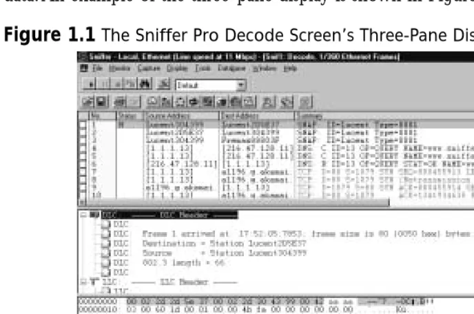
A network analyzer is a troubleshooting tool that is used to find and solve network communication problems, plan network capacity, and perform network optimization. Network analyzers can capture all the traffic that is going across your network and interpret the captured traffic to decode and interpret the different protocols in use.The decoded data is shown in a format that makes it easy to understand. A network analyzer can also capture only traffic that matches only the selection criteria as defined by a filter.This allows a technician to capture only traffic that is relevant to the problem at hand. A typical network analyzer displays the decoded data in three panes:
■ Summary Displays a one-line summary of the highest-layer protocol
contained in the frame, as well as the time of the capture and the source and destination addresses.
A network professional can easily use this type of interface to analyze this data. An example of the three-pane display is shown in Figure 1.1.
Network analyzers further provide the ability to create display filters so that a network professional can quickly find what he or she is looking for.
Advanced network analyzers provide pattern analysis capabilities.This feature allows the network analyzer to go through thousands of packets and identify problems.The network analyzer can also provide possible causes for these prob-lems and hints on how to resolve them.
N
OTESniffer Pro comes with a feature known as the Expert that analyzes frames on the network, compares them against its database of protocols and standards, and finds potential problems on the network. The Sniffer Pro Expert also provides possible causes of problems as well as potential solutions. You will learn about the Expert in Chapter 3, “Exploring the Sniffer Pro Interface.”
Troubleshooting Methodology
The key to successful troubleshooting is knowing how the network functions under normal conditions.This knowledge allows a network professional to quickly recog-nize abnormal operations. Using a strategy for network troubleshooting, the
problem can be approached methodically and resolved with minimum disruption to customers. Unfortunately, sometimes even network professionals with years of expe-rience have not mastered the basic concept of troubleshooting; a few minutes spent evaluating the symptoms can save hours of time lost chasing the wrong problem.
A good approach to problem resolution involves these steps:
1. Recognizing symptoms and defining the problem
2. Isolating and understanding the problem
3. Identifying and testing the cause of the problem
4. Solving the problem
5. Verifying that the problem has been resolved
N
OTEA very important part of troubleshooting is performing research. The Internet can be a valuable source of information on a variety of network topics and can provide access to tutorials, discussion forums, and refer-ence materials. As a part of your troubleshooting methodology, you can use the Internet as a tool to perform searches on errors or symptoms that you see on your network.
The first step toward trying to solve a network issue is to recognize the symptoms.You might hear about a problem in one of many ways: an end user might complain that he or she is experiencing performance or connectivity issues, or a network management station might notify you about it. Compare the problem to normal operation. Determine whether something was changed on the network just before the problem started. In addition, check to make sure you are not troubleshooting something that has never worked before.Write down a clear definition of the problem.
the problem.The best approach to reducing the problem’s scope is to use divide-and-conquer methods.Try to figure out if the problem is related to a segment of the network or a single station. Determine if the problem can be duplicated else-where on the network.
The third step in problem resolution is to identify and test the cause of the problem and test your hypothesis.You can use network analyzers and other tools to analyze the traffic. After you develop a theory about the cause of the problem, you must test it.
Once a resolution to the problem has been determined, it should be put in place.The solution might involve upgrading hardware or software. It may call for increasing LAN segmentation or upgrading hardware to increase capacity.
The final step is to ensure that the entire problem has been resolved by having the end customer test for the problem. Sometimes a fix for one problem creates a new problem. At other times, the problem you repaired turns out to be a
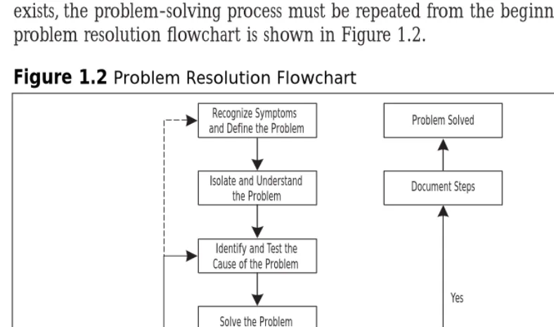
symptom of a deeper underlying problem. If the problem is indeed resolved, you should document the steps you took to resolve it. If, however, the problem still exists, the problem-solving process must be repeated from the beginning.The problem resolution flowchart is shown in Figure 1.2.
Figure 1.2Problem Resolution Flowchart
Recognize Symptoms and Define the Problem
Isolate and Understand the Problem
Identify and Test the Cause of the Problem
Solve the Problem
Verify Problem Resolution
Do problem symptoms
stop? Document Steps Problem Solved
The OSI Model, Protocols, and Devices
To understand network analysis, it is very important to learn the theory behind how networks operate. For a network to work, the computers running on it need to agree on a set of rules. Such a set of rules is known as a protocol. A protocol in networking terms is very similar to a language in human terms.Two computers using different protocols to talk to each other would be like someone trying to communicate in Japanese to another person who did not understand that lan-guage. It simply would not work!
Many protocols exist in today’s world of network communication. In the early days of networking, each networking vendor wrote their own protocols. Eventually, standards were developed so that devices from multiple vendors could communi-cate with each other using a common protocol. Examples of these protocols include Transmission Control Protocol/Internet Protocol (TCP/IP), Internetwork Packet Exchange/Sequence Packet Exchange (IPX/SPX), and AppleTalk.
N
OTETo be a successful network troubleshooter, you need a strong under-standing of network protocols. Underunder-standing different protocols and their characteristics will help you recognize abnormal behavior when it occurs in your network.
N
OTEThis book will show you, in detail, how to capture, view, decode, filter, and dissect many different protocol suites with the Sniffer Pro network analyzer.
The OSI Model and the DOD Model
In the early 1980s, the International Standards Organization (ISO) created the Open Systems Interconnection (OSI) model, which describes how network pro-tocols and components work together.The OSI reference model divides network protocol functions into seven layers. Each layer represents a group of related spec-ifications, functions, and activities.
The seven layers of the OSI model are shown in Figure 1.3. A layer in the OSI model provides services to the layer above it and, in turn, relies on the ser-vices provided by the layer below it. Encapsulation is the process by which infor-mation from an upper layer of the model is inserted into the data field of a lower layer. As a message leaves a networked station, it travels from Layer 7 to Layer 1. Data created by the application layer is passed down to the presentation layer.The presentation layer takes the data from the application layer and adds its own header and trailer to it.This data is then passed down to the session layer, which adds its own header and trailer and passes it down to the transport layer.The pro-cess repeats itself until the data reaches the physical layer.The physical layer does not care about the meaning of the data. It simply converts the data into bits and places it on the transmission media.
Figure 1.3The OSI Reference Model’s Seven Layers
7 6 5 4 3 2 1
Network
Physical Data Link Transport Session Presentation
N
OTEThe data that comes from an upper layer to a lower layer, including the upper layer headers and trailers, is known as the payload for the lower layer.
When the data arrives at its destination, the receiving station’s physical layer picks it up and performs the reverse process (also known as decapsulation).The physical layer converts the bits back into frames to pass on to the data link layer. The data link layer removes its header and trailer and passes the data on to the network layer. Once again, this process repeats itself until the data reaches all the way to the application layer.
The layers of the OSI model are:
■ Application layer This topmost layer of the OSI model is responsible
for managing communications between network applications.This layer is not the application itself, although some applications may perform application layer functions. Examples of application layer protocols include File Transfer Protocol (FTP), Hypertext Transfer Protocol (HTTP), Simple Mail Transfer Protocol (SMTP), and Telnet.
■ Presentation layer This layer is responsible for data presentation,
encryption, and compression.
■ Session layer The session layer is responsible for creating and managing
sessions between end systems.The session layer protocol is often unused in many protocols. Examples of protocols at the session layer include NetBIOS and Remote Procedure Call (RPC).
■ Transport layer This layer is responsible for communication between
programs or processes. Port or socket numbers are used to identify these unique processes. Examples of transport layer protocols include Transmission Control Protocol (TCP), User Datagram Protocol (UDP), and Sequence Packet Exchange (SPX).
■ Network layer This layer is responsible for addressing and delivering
■ Data link layer This layer is responsible for delivering frames between
network interface cards (NICs) on the same physical segment. Communication at the data link layer is generally based on hardware addresses.The data link layer wraps data from the network layer inside a frame. Examples of data link layer protocols include Ethernet,Token Ring, and Point-to-Point Protocol (PPP). Devices that operate at this layer include bridges and switches.
■ Physical layer This layer defines connectors, wiring, and the
specifica-tions on how voltage and bits pass over the wired (or wireless) media. Devices at this layer include repeaters, concentrators, and hubs. Devices that operate at the physical layer do not have an understanding of paths.
The OSI model is very generic and can be used to explain virtually any net-work protocol.Various protocol suites are often mapped against the OSI model for this purpose. A solid understanding of the OSI model aids tremendously in network analysis, comparison, and troubleshooting. However, it is also important to remember that not all protocols map nicely to the OSI model. For example, TCP/IP was designed to map to the U.S. Department of Defense (DoD) model.
In the 1970s, the DoD developed its four-layer model.The core Internet pro-tocols adhere to this model.The DoD model is merely a condensed version of the OSI model. Its four layers are:
■ Process layer This layer defines protocols that implement user-level
applications such as mail delivery, remote login, and file transfer.
■ Host-to-host layer This layer handles the connection, data flow
man-agement, and retransmission of lost data.
■ Internet layer This layer is responsible for delivering data from source
host to destination host across a set of different physical networks that connect the two machines.
■ Network access layer This layer handles the delivery of data over a
particular hardware media.
TCP/IP
Internet Protocol (IP) is a Layer 3 protocol that contains addressing and con-trol information that allows packets to be routed. IP is a connectionless protocol, therefore, it provides unreliable best-effort packet delivery service. Since IP only provides best effort delivery, a packet may be discarded during transmission. All IP packets consist of a header and a payload (data from upper layers). Figure 1.5 shows the format of an IP packet.
N
OTEIf reliable, guaranteed transfer is needed, IP depends on TCP to provide this functionality. TCP is a connection-oriented protocol that runs on top of IP and provides sequencing and acknowledgments.
At the transport layer of the TCP/IP stack, the two commonly used protocols are TCP and UDP.The headers for both of these protocols include a source and destination port number, which are used to determine the application or process that the TCP segment or UDP datagram originate from and destined to.TCP is a Figure 1.4The TCP/IP Protocol Stack Layers
Ethernet / IEEE 802.3
Telnet, FTP, SMTP, SNMP, DNS, POP3, IMAP4, and others 7
6 5 4 3 2 1
IP Token Ring /
IEEE 802.5 Other Media Access Protocols UDP TCP
Figure 1.5The Format of an IP Packet
Time To Live
Source Address Destination Address
Options + Padding Data
Protocol Header Checksum Identification
connection-oriented protocol, and UDP is a connectionless protocol.The TCP header includes sequence and acknowledgment numbers for reliable delivery. TCP can also use the sliding window principle.The sliding window algorithm allows a buffer to be placed between the application program and the network data flow. Data received from the network is placed into this buffer until the application is ready to read it.The window is the amount of data that can be fetched into the buffer before an acknowledgment must be sent.
Examples of applications that use TCP include FTP,Telnet, Network File System (NFS), SMTP, HTTP, Domain Name System (DNS), and Network News Transfer Protocol (NNTP). Examples of applications that use UDP include DNS, Routing Information Protocol (RIP), NFS, Simple Network Management
Protocol (SNMP), and Dynamic Host Configuration Protocol/Boot Protocol (DHCP/BOOTP). As you can see, some applications (such as DNS and NFS) can use both protocols.
IP Addressing
TCP/IP uses IP addresses to send messages to their proper destinations. Every TCP/IP host in the network requires a unique IP address on each of its NICs. IP addresses are assigned by the network administrator, either manually or through a dynamic addressing protocol such as Reverse Address Resolution Protocol
(RARP), BOOTP, or DHCP.The current IP addressing scheme (IPv4) defines an IP address as a 32-bit binary number—for example:
11000111 00011010 10101100 01010011
To make it more convenient for us, the IP address is divided into four 8-bit octets (bytes):
11000111.00011010.10101100.01010011
These octets are then converted from binary to decimal numbers and written as follows (four decimal digits separated by periods):
199.26.172.83
When this number is entered into a computer, the machine automatically con-verts it to a 32-bit binary number, with no regard for the individual octets or the decimals.
entire network.The host ID identifies a specific device (host) within a segment and must be unique on a particular segment.
N
OTEThe IP system in common use today is known as IPv4, for Internet Protocol version 4. A newer system, IPv6, or Internet Protocol version 6, has been developed and exists today in small deployments. IPv6 allows for more addresses by increasing the address size from 32 bits to 128 bits.
Classes
When the original IP routing scheme was developed, IP addresses were divided into five classes. IP addresses most commonly come as Class A, B, or C. Class D addresses are used for multicasting, and Class E addresses are reserved for experi-mental and future use.The classes of IP addresses are shown in Table 1.1. Please note that in the table, N = Network and H = Host.
The values of the leftmost four bits of an IP address determine its class. All Class A addresses, for example, have the leftmost bit set to 0, but each of the remaining 31 bits may be set to a 0 or 1 independently (as represented by x in these bit positions):
0xxxxxxxx xxxxxxxx xxxxxxxx xxxxxxxx
This specifies the range of Class A addresses as 0.0.0.0 to 127.255.255.255. Class B addresses must have the leftmost bit set to 1 and the next bit set to 0; all other bits may vary:
10xxxxxx xxxxxxxx xxxxxxxx xxxxxxxx
Based on this rule, Class B addresses have a range of 128.0.0.0 to
191.255.255.255. Similarly, Class C, D, and E addresses set the second, third, and fourth bits (respectively) to 1.
N
OTEClasses A, B, and C define a default subnet mask for the addresses in their ranges. A subnet mask separates the network portion of an IP address from the host portion. In a Class A address, the first octet represents the network ID, and the last three octets represent the host ID. In a Class B address, the first two octets represent the network ID, and the last two octets represent the host ID. In Class C addresses, the first three octets are used for the network ID, and the last octet is the host ID.
Table 1.1IP Address Classes
Range Network/Host Default Class Leftmost Bits (first octet) Portions Subnet Mask
A 0xxxxxxx 0–127 N.H.H.H 255.0.0.0 B 10xxxxxx 128–191 N.N.H.H 255.255.0.0 C 110xxxxx 192–223 N.N.N.H 255.255.255.0 D 1110xxxx 224–239 Not applicable Not applicable E 1111xxxx 240–255 Not applicable Not applicable
N
OTEClassless interdomain routing (CIDR) was introduced on the Internet to
improve the scalability of the Internet routing system and to allow for more efficient allocation of addresses. CIDR uses variable-length subnet
masks (VLSMs) and eliminates the concept of classful networks. This is
also known as classless routing.
Binary to Hex to Decimal Translation
We generally use the base10 (also known as decimal) numbering system, which uses 10 values (0, 1, 2, 3, 4, 5, 6, 7, 8, 9) to represent numbers.
8 bits. Most modern computers also have 8 bits in a byte. In the early days of computers, the word byte was also used to describe other quantities of bits.The term nibble is equal to half a byte and is therefore 4 bits, in most cases.
Hexadecimal is base16 and therefore uses 16 values (0, 1, 2, 3, 4, 5, 6, 7, 8, 9, A, B, C, D, E, F) to represent numbers.The hexadecimal system is useful because a byte (8 bits) of binary data can be represented using just two hexadecimal digits.This makes it easier for humans to read or write large numbers in hexadec-imal rather than binary format.
We will first learn how to convert a decimal number into binary. A popular method for converting a decimal number into binary is to divide the number by 2 repeatedly. Let’s take the decimal number 35 as an example. Figure 1.6 shows how this decimal number can be converted into binary format. Here are the steps:
1. Divide the original number by 2.The remainder becomes the least significant bit in the binary number.
2. Divide the result of the division from Step 1 by 2.The remainder becomes the next most significant bit of the binary number.
3. Repeat the division process until the result is 0.The remainders form the binary number.
Let’s now look at binary-to-decimal conversion. Here we simply multiply the binary digits by increasing powers of 2, starting from the right. Let’s walk through the steps involved in converting the binary number 101 into decimal format:
1. The rightmost digit is a 1, so you multiply it by 2 to the 0th power (or 1): 1 ×1 = 1.
2. Multiply the next digit to the left (0) by 2 to the first power (or 2): 0 ×2 = 0.
Figure 1.6Conversion of the Decimal Number 35 into Binary Format
35 divided by 2 = 17 Remainder 1 17 divided by 2 = 8 Remainder 1 8 divided by 2 = 4 Remainder 0 4 divided by 2 = 2 Remainder 0 2 divided by 2 = 1 Remainder 0
3. Multiply the next digit to the left (1) by 2 to the second power (or 4): 1 ×4 = 4.
4. Now, to find the decimal number, you find the sum of these products: 1 + 0 + 4 = 5.Therefore, 101 in binary equals 5 in base 10.
Hexadecimal-to-binary conversion is easily accomplished by converting each hexadecimal digit to decimal first and then converting each of these decimal values into binary. As an example, take the hexadecimal number 05DC:
1. Convert each digit to decimal, one by one.This results in the decimal values 0, 5, 13, and 12.
2. Convert each of these decimal numbers into 4 bits of binary.This gives us the binary values 0000, 0101, 1101, and 1100.
3. Put these binary values next to each other.We get 0000010111011100.
To convert binary to hexadecimal, reverse this method. Group the binary number into 4-bit nibbles, and convert each group into decimal. Finally, replace each decimal number with its hex equivalent. As an example, take the binary value 1101101101010110:
1. When we divide the value into 4-bit nibbles, we get 1101, 1011, 0101, and 0110 (the first line in Figure 1.7).
2. Convert each nibble into its decimal equivalent.This results in 13, 11, 5, and 6 (the second line in Figure 1.7).
3. Replace each decimal number with its hex equivalent.This results in the final value of DB56 (the third line in Figure 1.7).
Figure 1.7Converting the Binary Number 1101101101010110 into Hex Format
1 1 0 1 1 0 1 1 0 1 0 11 0 1 1 0
13 11 5 6
N
OTEYou will find that knowing how to perform base conversion is essential to a network analyst’s job. Computer data, including networking proto-cols, is often represented in binary or hexadecimal format.
IPX/SPX
Internetwork Packet Exchange/Sequenced Packet Exchange (IPX/SPX) is a Novell communications protocol suite derived from the Xerox Network System (XNS) protocol. Figure 1.8 shows how the IPX/SPX protocol stack maps against the OSI reference model.
IPX is a connectionless Layer 3 network protocol. Although multiple Novell protocols operate at Layer 4, SPX is the most common one. SPX, a reliable, con-nection-oriented protocol, was derived from the XNS Sequenced Packet
Protocol (SPP). Network Core Protocol (NCP) provides interaction between clients and servers by defining connection control and service request/reply. Service Advertisement Protocol (SAP) allows servers to advertise their addresses and the services they provide.
Figure 1.9 shows an example of an IPX packet captured with Sniffer Pro.
IPX Addressing
An IPX address consists of two parts: the network number and the node number. IPX addresses are 80 bits long, with 32 bits for the network number and 48 bits for the node number. IPX simplifies mapping between Layer 3 and Layer 2 Figure 1.8Layers of the IPX/SPX Protocol Stack
Ethernet / IEEE 802.3
Netware Core Protocol (NCP) 7
6 5 4 3 2 1
SAP SPX
IPX Token Ring /
IEEE 802.5 FDDI ARCnet
addresses, using the Layer 2 address as the host portion of the Layer 3 address. This eliminates the need for an address resolution protocol such as Address Resolution Protocol (ARP) for IP. IPX addresses are generally written as hex-adecimal digits in the network.node format.
Unlike IP, IPX has no concept of subnetworking.The IPX network number is manually assigned and must be unique for each network segment. Each node number on a given IPX network segment must be unique.
N
OTEIPX supports multiple Ethernet frame types: Ethernet II, IEEE 802.3, IEEE 802.3 SNAP, and Novell 802.3 RAW. (Frame types are discussed in detail later in the chapter.) It is possible to use multiple encapsulation types on a single network segment as long as a unique network number is
assigned to each encapsulation type. It is important to note that hosts that use different encapsulation types will not be able to directly com-municate with each other.
Internal Network Numbering and Server Addresses
IPX contains two types of network numbers: internal network numbers and work numbers assigned to local area network (LAN) and some wide area net-work (WAN) interfaces (sometimes called “external” netnet-work numbers).An
internal network number identifies an extension of your internal network,
some-times referred to as a virtual network segment. For example, a router will add an additional hop en route to a workstation if you have configured your internal network number on a workstation running IPX.
The use of an internal network number allows for improved fault tolerance on the network. IPX resources are referenced by SAP names that point to an IPX address. Using an internal network number as a part of the SAP address means that in the event of a failure of a particular network segment, only the IPX route, not the SAP tables, will have to be adjusted to an alternate path.
The internal network number is an eight-digit hexadecimal number between 0x1 and 0xFFFFFFFE and must be unique cross the entire IPX network.
Although 0xFFFFFFFE was originally allowed for use as an address, this changed after the introduction of Network Link Services Protocol (NLSP). Both NLSP and IPX RIP have been modified since then to recognize 0xFFFFFFFE as the default route.When you use the internal network number, the host portion of the IPX address is set to 1.
How to Translate an IPX Address
Figure 1.10 describes an IPX address in more detail.The first 32 bits of the address are the network number and are configured by the network adminis-trator.This number must be a hex value between 0x00000001 and 0xFFFFFFFD. In this case, the network number is configured as the hex value 0xBEEF.The last 48 bits of the address are the same as the Media Access Control (MAC) address and come from the NIC. In this case, the MAC address of the NIC is 00-20-E0-88-80-74, which is also used as the IPX node number.
Figure 1.10Example of an IPX Address
N
OTEThe default behavior for an IPX node is to adopt the NIC’s MAC address as the IPX node number. However, a network administrator can choose to override this behavior by statically assigning an IPX node number to a system. Be careful, however! If the assigned node number is not unique on the network, you may end up with two systems on the network with the same IPX node number. This can cause serious network problems. You can use the Sniffer Pro software to find duplicate node numbers assigned on a network.
AppleTalk
Apple Computer developed AppleTalk as a Plug and Play protocol for use on Macintosh computers. AppleTalk was designed to allow sharing of resources such as files and printers among multiple users. Any device attached to an AppleTalk network is known as a node. Figure 1.11 shows how the AppleTalk protocol stack maps against the OSI reference model.
AppleTalk supports four media-access protocols:
■ EtherTalk AppleTalk over Ethernet ■ LocalTalk AppleTalk over phone wire ■ TokenTalkAppleTalk over Token Ring
■ FDDITalk AppleTa