R E S E A R C H
Open Access
Craniofacial reconstruction based on a
hierarchical dense deformable model
Yongli Hu
1, Fuqing Duan
2, Mingquan Zhou
2, Yanfeng Sun
1*and Baocai Yin
1Abstract
Craniofacial reconstruction from skull has deeply been investigated by computer scientists in the past two decades because it is important for identification. The dominant methods construct facial surface from the soft tissue thickness measured at a set of skull landmarks. The quantity and position of the landmarks are very vital for craniofacial
reconstruction, but there is no standard. In addition, it is difficult to accurately locate the landmarks on dense mesh without manual assistance. In this article, we propose an automatic craniofacial reconstruction method based on a hierarchical dense deformable model. To construct the model, we collect more than 100 head samples by computerized tomography scanner. The samples are represented as dense triangle mesh to model face and skull shape. As the deformable model demands all samples in uniform form, a non-rigid registration algorithm is presented to align the samples in point-to-point correspondence. Based on the aligned samples, a global deformable model is constructed, and three local models are constructed from the segmented patches of the eye, nose, and mouth. For a given skull, the global and local deformable models are matched with it, and the reconstructed facial surface is obtained by fusing the global and local reconstruction results. To validate our method, a face deformable model is constructed and the reconstruction results are evaluated in its coefficient domain. The experimental results indicate that the proposed method has good performance for craniofacial reconstruction.
Keywords: Craniofacial reconstruction, Hierarchical deformable model, Dense mesh registration
Introduction
Craniofacial reconstruction is an efficient method to get a visual outlook of an individual in the case of only skull and bone remaining. The traditional plastic methods [1-3] depend on the time-consuming manual work of artists. The reconstruction result is generally determined by the experience of practitioners. To reduce reconstruction time and eliminate subjective biases, different computer-aid craniofacial reconstruction methods have been pro-posed [4-17]. The state-of-the-art of the computer-aid craniofacial reconstruction have comprehensively been reviewed in the surveys [18-21]. The soft tissue thickness measured on skull is the foundation for craniofacial recon-struction. To get complete tissue thickness, the head sam-ples are usually measured by different equipments such
*Correspondence: yfsun@bjut.edu.cn
1Beijing Key Laboratory of Multimedia and Intelligent Software Technology, College of Computer Science and Technology, Beijing University of Technology, Beijing 100124, China
Full list of author information is available at the end of the article
as computerized tomography (CT), magnetic resonance imaging and ultrasound scanner. Most computer-aid craniofacial reconstruction methods fit a selected facial template to the target skull according to the average soft tissue thickness at the skull landmarks [4-8]. Others deform a reference skull to match the remaining skull according to the skull feature such as anthropologic points [9], lines [10], and other features [11]. Applying an extrap-olation of the skull deformation to the face template, the reconstructed face will be achieved.
The selection of the template or reference is vital for accurate craniofacial reconstruction. In general, a generic or a specific craniofacial template with similar shape attributes is chosen. But it is difficult to get suitable ref-erence for every dry skull because of the diversity of skull and face modality. In addition, as the complex deforma-tion between the reference and the target skull, the warp-ing methods should intensively be studied to get accurate reconstruction result. So many deformation methods are proposed to model the non-rigid shape deformation of
skull and face, such as radial basis functions (RBF) [22,23], or more exactly, a thin plate spline (TPS)-based defor-mation [12,24,25] for its smoothness. Instead of using fixed template, the recently proposed statistical craniofa-cial reconstruction methods [12-17] construct a type of deformable model from a set of 3D heads by the prin-ciple component analysis (PCA) technique. The statistic deformable model can be regarded as a dynamic tem-plate for the given skull. The temtem-plate deformation is a model fitting procedure driven by the difference between the input skull and the template, in which the model parameters are adjusted by optimization method. The reconstruction result of the deformable model depends on the diversity of samples in the 3D heads database. If there are sufficient samples, good reconstruction results will be achieved. So the statistic method is regarded as the dominant method with great potential application in practice.
Essentially, the craniofacial reconstruction is to figure out the face of unknown skull by the knowledge of skull and face dependency, which is concretely represented as the distribution of the tissue thickness on skull. Most current methods utilize the soft tissue thickness of a set of skull landmarks for craniofacial reconstruction, but it is considered not an ideal approach to model the rela-tionship between face and skull. One reason is that the statistical soft tissue thickness at a set of sparse landmarks is far less than enough to reflect the whole distribution of tissue depth. The other reason is that the quantity and position of the landmarks are indefinite. Different landmark sets have been proposed for craniofacial recon-struction [26-31], though there are definite anatomical points in biometrics [32,33]. Moreover, it is difficult to detect the landmarks accurately on the complex surface of skull without manual interactive work. In order to reflect the complete tissue thickness distribution and eliminate the disadvantages of the sparse representations, the meth-ods which measure tissue depth at all points have been proposed. In these methods, the face and skull are gen-erally represented in dense form. For examples, Tu et al. [34] constructed a face space for craniofacial reconstruc-tion from the dense skull and face surfaces extracted from head CT images. Vandermeulen et al. [35] also used dense representations (implicit surfaces) for both skin and skull in craniofacial reconstruction. Pei et al. [22] presented a dense tissue depth image representation for craniofa-cial reconstruction, namely tissue-map. The dense tissue depth methods utilize more information of the relation-ship between skull and face, it generally has better cran-iofacial reconstruction results. To represent the dense tissue depth exactly, the dense point registration of skull or face is usually demanded. Although many registration methods [12,24,25,36] have been proposed to construct correspondence between surfaces and point sets, it is still
a challenging problem for further investigation because of the complex skull mesh with gross errors or outliers.
To the complex skull and face surfaces, the modality variety is composed of global shape and local detail. How-ever, most current craniofacial reconstruction systems generally take the whole face or skull for shape analysis, while the local feature of skull and face is not emphasized. The recent research reveals that the local shape model is better than the global model to represent local shape vari-ety [37,38]. Inspired by this point, we propose a hierarchi-cal craniofacial reconstruction model which integrates the global model with several local models to improve cran-iofacial reconstruction result. To construct the model, the face and skull samples are represented as dense mesh and aligned in point-to-point form by a proposed auto-matic dense registration algorithm, which contributes to a fully automatic craniofacial reconstruction method. In addition, to get valid evaluation for the craniofacial recon-struction results, we transform the reconstructed face into the coefficient domain of a face deformable model and the distance in the coefficient space is used as the similarity measurement. Comparing with the current measurement methods, such as the mean correspondence point dis-tance or the Euclidean disdis-tance matrix [12], the proposed measurement is more suitable for face recognition.
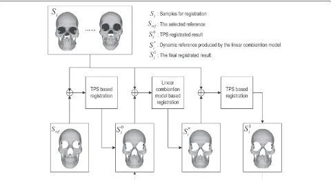
The proposed hierarchical craniofacial reconstruction system is composed of four components, namely, the data acquisition and preprocessing, the global deformable model, the local deformable model, and the result eval-uation (the dashed rectangles shown in Figure 1). In the data acquisition and preprocessing component, skull and face data are acquired by CT scanner and the prototypic data are preprocessed to construct 3D skull and face sur-faces. To construct the model, all samples are aligned by a proposed non-rigid dense mesh registration algorithm. In the global/local deformable model components, the global/local deformable models are constructed and the global/local face reconstruction results are obtained by model-matching procedure. Fusing the global and local reconstruction results gives the final craniofacial recon-struction result. In the result evaluation component, the reconstruction result is evaluated and the validation of the proposed method is verified. To integrate the four com-ponents as a whole system, some key problems, such as the dense mesh registration, the model matching proce-dure, the mesh segment, and fusion (the small rectangles shown in Figure 1) should be solved. In the rest of the arti-cle, we will give the detail of the main components and the solutions to these key problems.
Data acquisition and preprocessing
Figure 1The framework of the hierarchical craniofacial reconstruction.
multi-slice CT scanner (Siemens SOMATOM Sensation 16) in the affiliated hospital of Shaanxi University of Chinese Medicine located in western China. More than 100 patients planned for preoperative osteotomy surgery gave informed consent to scan the whole head for scien-tific research. The images of each subject are stored in DICOM 3.0 with 512×512 resolution. To get complete head data, 250 to 320 slices are captured for different per-sons. Most of the patients belong to the Han ethnic group in northern China. In this article, 110 samples are used for craniofacial reconstruction experiments. There are 48 female and 62 male subjects in the collection. The age distribution ranges from 20 to 60.
Each prototypic sample in our database consists of a skull surface and its face surface, which are extracted from CT images. The point clouds composing of the outer surfaces of skull and skin are extracted slice by slice (Figure 2a). For the skull, a three-step method is per-formed on each slice of CT images. The first step is to find the contour points of the skull through the Sobel operator model after filtering out noise. In general, the skull con-tour has inter and outer sides (Figure 2). In the second step, a circular scanning is implemented to get a rough outer contour. The scanning line is radiated from the cen-ter of the image, toward the four edges of the image, to find the farthest contour point it encounters. The rough contour usually contains some points not belonging to the outer surface, as shown in Figure 2c. In the last step, these pseudo contour sections are removed and the miss-ing parts are mended. By settmiss-ing the max length threshold
L, the section will be deleted if its length is smaller than
L pixels. In our experiment, L is set to be 10. Because the skull is non-convex, the rough contour may disrupt in some regions where it should be connected. We adopt an 8-neighborhood boundary tracing approach to connect each point of the rough contour if they are disrupted, and obtain the final contour, as shown in Figure 2d. It is eas-ier for skin to find the outer contour, as the skin contour is simple and generally close for all CT images (Figure 2e). So we only need to find a point in the above second step to get the outer skin contour, as shown in Figure 2f. After retrieving the outer contours for skull and skin from all CT images, the skull and face surfaces can be represented as triangle meshes by the marching cube algo-rithm [39]. Usually, the raw skin surface consists of about 220,000 points with 450,000 triangles, while the skull sur-face contains about 150,000 points with 320,000 triangles, as shown in Figure 2g–j. It is dense enough to describe the rich details of skull and face shapes.
Figure 2Data acquisition and preprocessing.(a)The head slice captured by CT scanner.(b–d)The skull contour extracting procedure.(e, f)The skin contour extraction.(g–j)The reconstructed 3D skull and face in point cloud and triangle mesh formation.(k, l)The uniform coordinate system of the skull and face samples.
Oand has the same direction as the normal of the Frank-furt plane is set asz-axis.y-axis is obtained by the cross product ofz- andx-axis. The scale of the samples is stan-dardized by setting the distance betweenLpandRpto unit, i.e., every vertex(x,y,z)of the skull and face is replaced by(|Lx
pRp|, y |LpRp|,
z
|LpRp|). The uniform coordinate system of
skull and face is shown in Figure 2k,l.
Dense registration for skull and face
The original skull and face meshes have different con-nectivity with different number of vertices. To investi-gate the modality variety of skull and face, the original skull and face samples must be registered before model construction. For the samples in dense triangle mesh representation, the registration is to build a point-to-point correspondence according to the shape features, such as the tip of nose, the corner of mouth, and the center of eyes. It is a challenging problem to get accu-rate registration for dense skull and face meshes because there exists non-rigid deformations and big-block out-liers on the complex surfaces. To solve the problem of
volume and easily fails for big-block outliers. In this arti-cle, we present a two-step method to solve the dense registration of skull and face. The first step is to align two samples by a non-rigid registration method based on the TPS transformation [45]. The second step is to improve the registration of all samples by a group regis-tration method based on a linear combination model. The proposed method is implemented automatically and has good performance for big-block outliers. The whole pro-cedure of our registration method is shown in Figure 3. The detail is given in the following sections.
TPS-based non-rigid registration
As the skull and face have complex shape modality with non-rigid deformation, the traditional rigid registration methods, for example, the widely used ICP algorithm [46], are not suitable for this problem. So we adopt non-rigid registration method to solve the dense registration of skull and face. The basic idea of the method is shown in Figure 4, not constructing registration between the refer-ence and the target directly, we construct an approaching template for the target skull or face from the non-rigid deformation of the reference. As the deformed reference is closer to the target than the reference, it will produce more accurate alignment. Considering the advantages of TPS deformation, such as good smoothness constraint, simple calculation, and the ability to be decomposed into affine transformation component and non-affine trans-formation component, we adopt TPS to represent the
non-rigid deformation. There are two steps to make the registration between the reference and the target. First, the reference is transformed to the target by TPS deforma-tion. Then, the point-to-point correspondence is achieved by the closest point searching procedure of ICP. The detail of the TPS-based non-rigid registration method is given in the following.
To begin the registration, the reference skull and face must be selected. In general, the head with common shape feature is used as the reference. We select a sample with complete data as the reference. Considering that the cran-iofacial reconstruction is mainly determined by the front part of head, the occipital parts of the reference are man-ually removed to reduce data volume. The back-removed reference skull and face are shown in Figure 5a,b. There are 36,000 and 40,969 vertices with 70,827 and 81,458 tri-angles on the reference skull and face, respectively. The other preparing work for the non-rigid registration is to get the controlling points for TPS transformation. As TPS is type of interpolation method, generally the TPS defor-mation depends on a set of correspondent controlling points on the reference and the target. But it is difficult to get plenty of correspondent feature points on face and skull automatically. It generally demands time-consuming manual work to locate the feature points on skull and face. To get automatic point registration, we use a ran-dom method to produce the controlling points for TPS, in which a mount of controlling points are generated ran-domly in the reference and its correspondent points on
Figure 4The TPS-based non-rigid registration and the traditional rigid ICP registration.
the target are obtained by ICP closest points searching method. To get uniform distribution on the 3D surface, the random controlling points are computed by the far-thest point sampling method [47]. The random points on the reference skull and face are shown in Figure 5c,d. As the correspondence obtained by the closest point search-ing method for the random points is not exactly the true correspondence according to skull and face feature, instead of making one-step transformation from the refer-ence to target, we do the TPS transformation in a stepwise procedure. At the same time, to eliminate the influence of inconsistent correspondence of some points, the random points on the reference are updated timely. Integrating
this controlling points generating procedure with the TPS deformation, the selected reference skull and face will gradually be aligned to the target skull and face.
For convenience, the selected reference skull or face is denoted by Sref= {Prp|Prp=(xrp,yrp,zrp),p= 1,. . .,N1}, and the target, theith sample, is denoted by Si = {Piq|Piq = (xiq,yiq,ziq),q = 1,. . .,N2}, whereN1
and N2 are the points number of Sref and Si such that N1≤N2. Then the TPS transformation can be regarded as a map fromSreftoSi, denoted byf(.). The correspondent random controlling point sets ofSref andSiare denoted by Mr = {Lrj|Lrj = (x∗rj,yrj∗,z∗rj),j = 1,. . .,M}, Mi =
{Lij|Lij =(x∗ij,y∗ij,z∗ij),j=1,. . .,M}, whereMis the count
of the controlling points. From the definition of TPS,f(.)
will satisfy the following interpolation conditions:
f(Lrj)=Lij,j=1,. . .,M (1)
By TPS theory, the deformation of other non-controlling points is restricted by the blending energy function in the following form:
E(f)=
R3
I3TFXFXTI3dxdydz (2)
where X = (x,y,z)T, FX = (∂∂xf,∂∂fy,∂∂fz)T and I3 =
(1, 1, 1)T. It is proved that TPS can be decomposed into affine and non-affine components [45]. This fact is gener-ally represented as the following formula:
f(P)=Pd+Kw (3)
where P ∈ Sref with the homogeneous coordinate
(1,x,y,z). d is a 4 × 4 affine transformation matrix. K
is the TPS kernel, a 1× Mvector in the form of K =
(K1(P),. . .,KM(P)), where Kj(P) = P − Lrj ,j = 1,. . .,M.wis aM×4 warping coefficient matrix repre-senting the non-affine deformation.
To solve TPS transformation, the matrixdandwmust be determined. There are two solutions to this problem, namely, the interpolating and non-interpolating methods. In the interpolating case, formula (1) is satisfied. Putting formula (3) into (1) and confiningwto non-affine trans-formation, i.e.,M1Tw=0, it leads to a direct solution for dandwformed by the following matrix relation:
w d
=
K Mr
MrT 0
Mi 0
(4)
whereMr andMiareM×4 matrixes corresponding to the controlling points sets Mr and Mi in homogeneous coordinate form.Kis aM×Msymmetry matrix repre-senting the spatial relation ofMrwith the elementkuv= Lru −Lrv ,u = 1,. . .,M,v = 1,. . .,M. In the non-interpolating case, formula (1) is not strictly satisfied. The following energy function can be minimized to find the optimized answer.
E(λ,w,d)= 1 M
M
j=1
Lij−f(Lrj) +λ·E(f) (5)
whereλis the weight to control the blending component, and given a fixed λthere is a unique minimum for the energy function. It is conducted that the non-interpolating solution has a parallel form replacing K in formula (4) by K+λI. As the correspondent controlling points on the reference and target acquired by ICP closest points searching is not exactly correct, the condition in formula (1) is not satisfied. So the non-interpolating method is adopted in this article.
Having determined the TPS transformation f(.), the
referenceSref can be deformed by the formula (3). The
deformed reference is denoted by Si. Then the corre-spondence betweenSiandSi can be obtained using ICP closest point searching. But the closest point searching procedure of ICP is a time consuming procedure with computation in O(N1× N2). To get high efficiency, we
adopt aK-dimensional binary search tree (KD-tree) [48] to model the target, which is proved having a complexity withO(N1×logN2)for the pairwise closest point
search-ing. Considering that the closest point matching based on the initial TPS deformation is more inaccurate and the beginning alignment refers to the global correspon-dence while the later to the local area, a deterministic annealing strategy is applied in the stepwise TPS-based registration procedure. At the beginning of the registra-tion, the points move a little to its deformed points, and the step size increases gradually when TPS deformation result becomes desirable. At the same time, the number of the random points increase from a small initial number for enhancing the holistic deformation at the beginning, and the blending weight of TPS in (5) decreases to relax the global constrains. The following gives the implemen-tation of the proposed non-rigid TPS-based registration method.
1. Create KD-tree for thei th sampleSi, denote it byTi;
2. Apply ICP alignment betweenSref,Si, then transform Srefby the rigid transformation of ICP, the
transformed sample is denoted bySi;
3. Produce random controlling point setMi∗with cardinality ofM forSi;
4. For each point inM∗i, search its correspondent point onSiby querying onTi, the correspondent point set
is denoted byMi;
5. Determine the TPS transformationf fromM∗i,Mi
with blending weightλ;
6. Apply the TPS transformationf onSi, the deformed Siis denoted bySi;
7. UpdateSiby adding a movement to each point
P∈Si:
P=P+δ(f(P)−P), wheref(P)∈Siandδis
the step size;
8. For eachP∈Si, search its correspondent point
P∈Siby querying onTi;
9. Update the parameters:
M=M+ M,δ=δ+ δ,λ=λ− λ, whereM, δandλare the pre-assigned increments;
10. If the iterationsl<l0and
1 N1
P∈SiP−P> ε0, wherel0is the given
maximum loops andε0is the given threshold, goto 3;
11. The final correspondence ofSrefandSiis achieved
from the equivalent correspondence ofSandSi,
In our experiments,Mranges from5001 to801 of the point number of the reference, l0 = 30, ε0 = 10−6, the
ini-tial δ = 0 withδ = l1
0, and the initialλ = 0.01 with λ=λ∗0.05.
Group registration by linear combination
It is important to select a closest reference for all samples to get good alignment, but the fixed reference may greatly differ with some samples as there is much variety in skull and face modality. Considering there are enough samples in our database, we try to improve the above registration by a group registration method based on a linear combi-nation model. Instead of using a fixed reference, we utilize the combination of the above aligned samples to generate dynamic reference for every samples. As the dynamic ref-erence is closer to the given sample, aligning the dynamic reference to the target sample will give better result. Based on the new correspondence result, we can construct new dynamic reference by linear combination, which will get more accurate aligning result. By this iterative procedure, the registration precise will be improved gradually. In the following, the iterative registration procedure by linear combination is described in detail.
If we regard the reference Sref as a N1× 1 vector in
form of(xr1,yr1,zr1,. . .,xrp,yrp,zrp,. . .,xrN1,yrN1,zrN1)T, then from the point-to-point correspondence, the N
aligned samples {Si0|i = 1,. . .,N} in the first-step can be formatted as vectors with the same form as Sref,
i.e.,Si0 = (xi1,yi1,zi1,. . .,xip,yip,zip,. . .,xiN1,yiN1,ziN1)T, where the point (xip,yip,zip) ∈ S0i is the correspondent point of(xrp,yrp,zrp). By this representation, we can get a new object by the following linear combination:
Snew(a)= N
i=1
aiS0i s.t. N
i=1
ai=1 (6)
wherea = (a1,. . .,aN)is the linear combination coeffi-cient vector. For each original sampleSi, a dynamic refer-enceS∗i can be determined by the following minimizing formula:
S∗i = N
i=1
a∗iS0i s.t. a∗=arg min
a Si−Snew(a)
(7)
where.defined as the vector module representing the difference between two samples. The overall difference for all samples is defined asEg = N1Ni=1 Si−S∗i . The following is the detail of the registration method.
1. AlignSrefto each sampleSiby TPS-based method
and get the primary aligning resultS0i;
2. Produce the dynamic referenceS∗i for eachSiby
linear combination;
3. Align the dynamic referenceS∗i toSiby TPS-based
method and get the aligning resultS1i;
4. If the iterations are less than the given maximum loops and the global differenceEgis great than the given threshold, updateS0i byS0i =Si1and goto 2; 5. Get the final aligning result from{S1i}.
The construction of the hierarchical deformable model
After computing dense correspondence, we can model all skulls and faces as the formation of the reference vec-tors by the point-to-point correspondence. If the triangle meshes of the reference skull and face are also applied on the correspondence points of the target, then all skulls and faces will have same mesh structure with same number of vertices. For convenience, we represent theith head sam-ple as a high dimension vector composed of skull and face vectors in the following form:
Hi=
Si Fi
i=1,. . .,N (8)
where Si = (xSi1,ySi1,zSi1,. . .,xSim,ySim,zSim)T and Fi = (xFi1,yiF1,ziF1,. . .,xFin,yFin,zFin)Tare the vectors of theith skull and face with dimensions of 3mand 3n, respectively.
Similar to the dynamic reference construction in the above section, the linear combination of the aligned head samples{Hi|i=1,. . .,N}will produce new skull and face. Given an unknown skull, the closest combination skull can be achieved by the model matching procedure. Extrapolat-ing the combination of the skull vectors to the face vectors in the model will get a reconstructed face for the given skull. The detail of the model matching will be given in the next section. As the prototypic skull and face samples have high dimension data with large redundance, PCA is applied to construct the following deformable model:
Hmodel(α)=H+ N
i=1
αihi (9)
whereH = N1 Ni=1Hi,{hi|i =1,. . .,N}are the former Ncomponents corresponding to the eigenvalues{σi|i = 1,. . .,N}of the covariance matrix of the subtracting vec-tors {Hi −H|i = 1,. . .,N} in descending order.N is determined by 98% of the cumulative eigenvalues of the variance. The combination coefficientα = (α1,. . .,αN) is the parameter for the deformable model. To generate a plausible face, the probability of α is constrained by the following formula:
P(α)∼exp
⎡ ⎣−1
2 N i=1 αi σi 2⎤ ⎦ (10)
shape variety, we construct several local deformable mod-els with respect to the main organs of face, the eye, nose, and mouth. The first step for constructing the local mod-els is to segment the organs. It is difficult to get an ideal automatic segment for different skull and face. As our samples have been aligned, getting the segments of the reference, the segments of other samples can be obtained from the correspondence of points. So we segment the local patches of the reference by hand. The segmented local patches of the reference are shown in Figure 4e–h. Based on the segmented data, the local models can be con-structed by the similar method of the global model. The hierarchical deformable model is constructed by integrat-ing the local models with the global model.
Craniofacial reconstruction
For a given skull, the craniofacial reconstruction is a model matching procedure, in which the coefficients of the deformable model are adjusted iteratively and the model combination skull approaches to the given skull gradually. To measure the difference between the model combination skullSmd(α)and the given skull, after assign-ing the initial values for the combination coefficients, we alignSmd(α)to the given skull by the TPS-based registra-tion. From the obtained correspondence, we format the given skull as a vectorSgv in the same form asSmd(α). So the difference between the given skull Sgv and the model combination skullSmd(α)can be represented as the square module of the subtracting vector as following form:
E(α) = Smd(α)−Sgv2
= (Smd(α)−Sgv)T(Smd(α)−Sgv) (11) Regarding this definition as the cost function, the recon-struction problem can be solved by an optimization method. It is denoted that the model combination skull
Smd(α)will change as the combination coefficients updat-ing in the optimization procedure. So the registration betweenSmd(α) andSgv is implemented every 20 loops to ensure the error in 11 computed in correct correspon-dence with the updatedSgv. To solve the optimization, we adopt a gradient descent algorithm to resolve the opti-mization problem. The core of the method is to find the gradient descent direction ofE(α)aboutα, which is equal to the negative derivative of E(α). From 11, the partial
derivative ofE(α)can be formed as follows:
E∂(α)
∂α =
S∂md(α)
∂α
T
(Smd(α)−Sgv)+(Smd(α)−Sgv)T
×
S∂md(α)
∂α
(12)
From formula 12, the partial derivative ofE(α)depends
on S∂md(α)
∂α , which can be deduced from formula 9 as the
formS∂md(α)
∂α = ∂(S+sα
T)
∂α = ∂(sα
T)
∂α , whereSis the skull part ofH,s=(s1. . .si. . .sN)andsiis the skull part ofhi. For
aαi, ∂(sα T)
∂αi =
∂(N i=1αisi)
∂αi =si. Putting it into 12 we get the
following partial derivative computation forαi:
E∂(α)
∂αi =
sTi (Smd(α)−Sgv)+(Smd(α)−Sgv)Tsi (13)
As the vectors si, S, and Sgv on the above formulas have the dimension same as the dimension of the ref-erence skull vector, it is time-consuming to implement the optimization of the gradient descent algorithm with the high dimension in 3m. To reduce computation, we extract a random sub-vectors of these vectors to replace them on the above equations. That is a subset indices {i0,. . .,im} are selected randomly from the continuous indices{1,. . .,m} in each gradient descent iteration. As
m m, the computation is greatly reduced. As the indices of the vector element is correspondent to the points on the skull, this method is equivalent to select a subset of random points, representing the model and given skull for similarity error computation. So the similar random point selection approach used in the TPS-based non-rigid registration can be applied here to get the ran-dom sub-vector. Considering that the model deformation scale is smaller than the deformation between the ref-erence and the target in data registration, and the local deformation dominates in the model matching, we use more quantity of random points in the model matching procedure. In our experiment, a subset with201 indices of the model skull vector is selected to implement the model matching computation. The maximal iteration is set to 500 for the global model and 1000 for the local models. To avoid the influences of noise and make use of the contribu-tion of every points, this random subset is updated at each iteration. However, this will lead instability for the error in 11 at the beginning tens of iterations, but it behaves steadily in the later iterations and converges to a minimal value. We have tested different sizes of random subsets in the model matching experiment, smaller size than the assigned number generally cannot get satisfied precision and even not convergent. While more points added in the subset, the improvement for the model matching is insignificant. By this model matching procedure, the best matched model skull will be obtained. Then the recon-structed face can be calculated by the combination of the face part ofhiin 9 with the same coefficients as the model skull.
reconstruction results generally are not consistent with the global result, especially at the boundary (shown in Figure 6a). To get a whole smooth reconstruction result, the fusion problem of the local and global results must be solved. We take two steps to integrate the global and local reconstruction meshes. For the global meshF and the sub-mesh Fsub, the local meshes are set onto the
global mesh in proper position using translation and rota-tion transformarota-tionR∗,T∗, whereR∗,T∗are determined by minimizing the average distance of the correspon-dent points of the sub-mesh and the global mesh, i.e., (R∗,T∗) = arg minR,T
P0∈FsubRP0+T−P1, where P1 ∈ F is the correspondent points ofP0. The first step
fusion result is shown in Figure 6b. Second, the incon-sistence at the boundary is removed by a mesh stitching algorithm, in which both the points on the sub-mesh and the global mesh near the boundary are deformed to an interspaced position by interpolation method. The detail of the mesh interpolation is shown in Figure 6d. For the sub-mesh boundaryB0and a pointP0 ∈ B0, we can get
the correspondent contour (denoted byB1) on the global
mesh and the correspondent pointP1 ∈ B1ofP0by the
above segmentation of the reference. Then the interpolat-ing pointP2is calculated byP2= (P0+2P1). Given a scalel0,
the boundaryB0will shrink into interior withl0step and
get a contourB0which is indicated by a pointQ0∈B0in
Figure 6d, while the counterB1shrink oppositely on the
global mesh and get a contourB1which is indicated by a pointQ1∈B1in Figure 6d. The stitching method is to find
a pair of interpolation functionsf0,f1have the following
conditions:
f0(Q0) = Q0,Q0∈B0 f0(P0)=P2,P0∈B0
f1(Q1) = Q1,Q1∈B1 f1(P1)=P2,Q1∈B1 (14)
There are many interpolation methods can be used to meet the above conditions, such as RBF function. For convenience, we adopt the above TPS to solve the
interpo-lation. Having determined the interpolation functions, the final fusion result (Figure 6c) can be achieved by applying
f0to the points between the contoursB0,B0on the sub-mesh andf1to the points between the contoursB1,B1on the global mesh.
Experimental results and discussion
Based on the dense aligned face and skull samples, a hier-archical deformable model is constructed for craniofacial reconstruction, which includes a global model and three local models, namely, the eye, nose, and mouth model. To validate the craniofacial reconstruction method, we implement a leave-one-out craniofacial reconstruction experiment, in which each skull is used as the test skull for craniofacial reconstruction, and the rest skulls and faces are used as the samples to build the hierarchical deformable model. Both the global and the local mod-els are matched to all tests. The final facial surfaces of the tests are reconstructed by the model matching and mesh stitching procedure. Some craniofacial reconstruc-tion results and its actual faces are shown in Figure 7.
The reconstructed faces of the hierarchical model are evaluated by comparing with their actual faces. First, the traditional measurement method is adopted for the evalu-ation, which adopts the average distance of correspondent points as the similarity measurement between 3D faces. We denote this method by ADCP. In ADCP method, the average reconstruction error of 110 tests are 0.01101 and 0.00998 for the global model and the hierarchical model with standard deviation 0.00297 and 0.00353, respectively. As the actual scale of our samples and the model has lost in the data preprocessing and coordinates uniforming procedure, we set the average distance between left and right porions to 15 cm according to the Chinese National Standard for Human Dimensions of Chinese Adult [49]. Then the average absolute error of correspondent points for the global and hierarchical model is 1.65 and 1.50 mm. Comparing with the results in [12,15], the result is accept-able considering that some important properties, such
Figure 7Some craniofacial reconstruction results.The actual faces are shown in columns 1, 3; the reconstructed faces are shown in columns 2, 4.
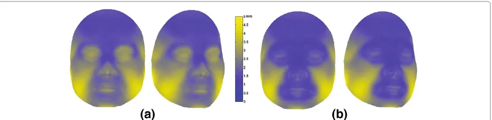
as Body Mass Index (BMI), age, and gender, are not integrated into the model. The distribution of the aver-age reconstruction error for every tests are shown as histogram in Figure 8. From the histogram, it is figured out that there are more tests with error less than 1.5 mm for the hierarchical model. The distribution of the aver-age reconstruction error for every points of the 110 tests is also computed and the results are displayed on the reference face in Figure 9. The figure shows that the hier-archical model have better reconstruction results than the single global model, especially in the areas related to the local models. It is concluded that using the local mod-els is beneficial to the improvement of the reconstruction accuracy.
Although ADCP is the dominant method for craniofa-cial reconstruction evaluation, it is not an ideal method considering that the aim of the craniofacial reconstruction is identification through face recognition. In general, the dense faces have very large quantity of points, the distance
changing on local area usually brings little changes to the average. As a result, the ADCP method is not sensitive to local shape change. But the local feature is important for face recognition, such as the width of mouth and the height of nose. The other drawback of ADCP is that every points have same weightiness in the distance computa-tion, though the points on different facial position have different effect for face recognition. To get proper evalu-ation for the craniofacial reconstruction result, we define a similarity measurement for reconstructed face inspired the ideas of face recognition, which uses the distance in the coefficient domain of a face deformable model as the measurement. The method is denoted by DCD. Similar to the above deformable model, the face deformable model is constructed from the aligned faces as follows:
Fmodel(β)=F+ k
i=1
0 0.5 1 1.5 2 2.5 3 3.5 4 4.5 5 0
5 10 15 20 25 30 35
The global model The hierarchical model
mm
Figure 8The histogram of the average reconstruction error of the global and hierarchical model for 110 tests.
whereFis the average face,{fi|i=1,. . .,k}are the former kcomponents. When two facesF1,F2are compared, their model coefficients β1, β2 are computed by the
model-matching procedure. Then the difference betweenF1and
F2 is measured by the distance between β1, β2 in the
coefficients space.
To get DCD measurement, 110 aligned faces are used to construct the face deformable model. Then the actual faces and the reconstructed faces of the global and hier-archical models are represented by the coefficients of the face model. The DCD distance between the reconstructed faces and its actual faces are calculated. The average reconstruction error of 110 tests are 0.1906 and 0.1837 for the global model and the hierarchical model with standard deviation 0.0516 and 0.0539, respectively. It is shown that the hierarchical model has better reconstruction results in DCD measurement method. To some extent, the dis-tance in the coefficients domain does not correlate to the distance of correspondent points. To explore the
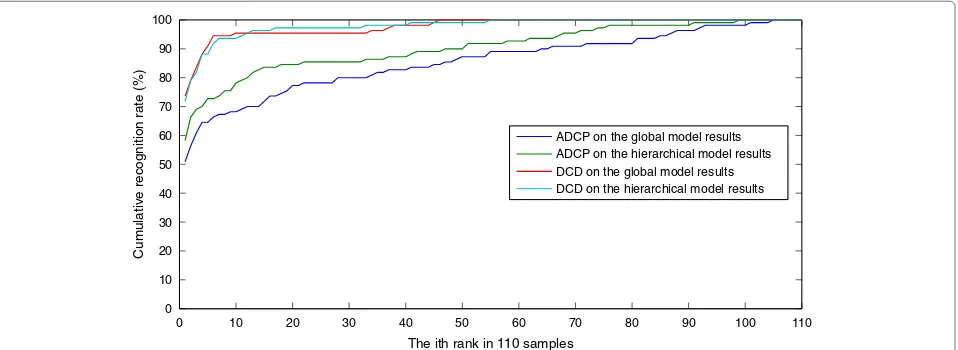
relation-ship between the presented DCD method and ADCP, we do a face recognition experiment, in which the closest real face to the reconstructed faces of the global and hierarchi-cal model is hierarchi-calculated in DCD and ADCP measurements, respectively. The cumulative recognition curves of the reconstruction results are shown in Figure 10. It shows that the face recognition results is great different for the two measurements. The cumulative recognition rate in DCD method is greater than that in ADCP method. And the hierarchical model generally has better recognition rate than the global model. These observations do not assuredly support that DCD is more suitable for evaluat-ing the reconstructed faces than ADCP. But it is concluded that DCD has good tolerance to the reconstruction error in face recognition application. As DCD is a distance mea-surement in the facial shape space which is constructed from a set of original samples. Gathering sufficient face samples, the DCD method may reflect the real measure-ment of the face space.
0 10 20 30 40 50 60 70 80 90 100 110 0
10 20 30 40 50 60 70 80 90 100
The ith rank in 110 samples
Cumulative recognition rate (%)
ADCP on the global model results ADCP on the hierarchical model results DCD on the global model results DCD on the hierarchical model results
Figure 10Cumulative recognition curves of the reconstruction results of the global and hierarchical model in ADCP and DCD methods.
Conclusion
We proposed a hierarchical dense deformable model for automatic craniofacial reconstruction. The feature of pro-posed model is that the skull and face are represented as dense mesh without landmarks. The advantage of this representation is that the dense meshes contain more meta-data for exploring the intrinsic relation between skull and face. In addition, the presented non-rigid dense meshes registration and the model matching procedure can be implemented automatically, which contributes to the fully automatic craniofacial reconstruction method. The craniofacial reconstruction experiments show that the hierarchical model has better reconstruction results than the single global model. The craniofacial reconstruc-tion evaluareconstruc-tion problem is also explored in this article. We present an evaluation method based on a deformable facial model. By comparing with the average distance of correspondent points method in face recognition experi-ment, the evaluation method may be the potential method for identification in the application of craniofacial recon-struction. In the future work, we plan to capture more head scans to increase the plenty of the samples, which is important for the model deformable capacity. Based on the abundant samples, the personal properties, such as gender, age, and BMI, are considered integrating with the hierarchical dense deformable model. The reconstruction result will be improved if these properties information are properly utilized. In addition, it is worthy of explor-ing ideal evaluation methods for the results of craniofacial reconstruction.
Competing interests
The authors declare that they have no competing interests.
Acknowledgements
This study was partly supported by the 973 Program of China (No. 2011CB302703) and the National Natural Science Foundation of China (Nos. 60825203, 61171169, 61133003, 60973057, 60736008, 61272363).
Author details
1Beijing Key Laboratory of Multimedia and Intelligent Software Technology,
College of Computer Science and Technology, Beijing University of Technology, Beijing 100124, China.2College of Information Science and Technology, Beijing Normal University, Beijing 100875, China.
Received: 31 October 2011 Accepted: 29 August 2012 Published: 9 October 2012
References
1. M Gerasimov,The Face Finder. (J.B Lippencott Co., Philadelphia, 1971) 2. C Snow, B Gatliff, KM Williams, Reconstruction of the facial features from
skull: an evaluation of its usefulness in forensic anthropology. Am. J. Phys. Anthropol.33, 221–228 (1970)
3. G Lebedinskaya, T Balueva, E Veselovskaya, inForensic Analysis of the Skull, ed. by MY Iscan and RP Helmer. Development of methodological principles for reconstruction of the face on the basis of skull material (Wiley-Liss Inc., New York, 1993)
4. P Vanezis, Application of 3-D computer graphics for facial reconstruction and comparison with sculpting techniques. Forensic Sci. Int.42, 69–84 (1989)
5. P Vanezis, M Vanezis, G McCombe, T Niblet, Facial reconstruction using 3-D computer graphics. Forensic Sci. Int.108, 81–95 (2000)
6. R Evenhouse, M Rasmussen, L Sadler, Computer-aided forensic facial reconstruction. J. Biocommun.19, 22–28 (1992)
7. AW Shahrom, P Vanezis, RC Chapman, A Gonzales, C Blenkinsop, ML Rossi, Techniques in facial identification: computer-aided facial reconstruction using laser scanner and video superimposition. Int. J. Legal Med.108, 194–200 (1996)
8. AJ Tyrell, MP Evison, AT Chamberlain, MA Green, Forensic three-dimensional facial reconstruction: historical review and contemporary developments. J. Forensic Sci.42, 653–661 (1997)
9. MW Jones, inProceedings of the Sixth International Vision Modelling and Visualisation Conference. Facial Reconstruction Using Volumetric Data, (Stuttgart, Germany, 2001), pp. 135–150
10. G Quatrehomme, S Cotin, G Subsol, H Delingette, Y Garidel, G Grevin, M Fidrich, A fully three-dimensional method for facial reconstruction based on deformable models. J. Forensic Sci.42, 649–652
(1997)
11. LA Nelson, SD Michael, The application of volume deformation to three-dimensional facial reconstruction: a comparison with previous techniques. Forensic Sci. Int.94, 167–181 (1998)
13. P Claes, D Vandermeulen, S De Greef, G Willems, P Suetens, Statistically deformable face models for cranio-facial reconstruction. CIT.14(1), 21–30 (2006)
14. P Claes, D Vandermeulen, S De Greef, G Willems, JG Clement, P Suetens, Bayesian estimation of optimal craniofacial reconstructions. Forensic Sci. Int.201, 146–152 (2010)
15. M Berar, FM Tilotta, JA Glaunes, Y Rozenholc, Craniofacial reconstruction as a prediction problem using a Latent Root Regression model. Forensic Sci. Int.210(1–3), 228–236 (2011)
16. M Berar, M Desvignes, G Bailly, Y Payan, 3d semi-landmark-based statistical face reconstruction. CIT.14(1), 31–43 (2006)
17. P Paysan, M Luthi, T Albrecht, A Lerch, B Amberg, F Santini, T Vetter, in
Proceedings of 31st DAGM Symposium for Pattern Recognition (DAGM’09). Face reconstruction from skull shapes and physical attributes, (Jena, Germany, 2009), pp. 232–241
18. P Claes, D Vandermeulen, S De Greef, G Willems, JG Clement, P Suetens, Computerized craniofacial reconstruction: conceptual framework and review. Forensic Sci. Int.201, 138–145 (2010)
19. Ch Stavrianos, I Stavrianou, L Zouloumis, D Mastagas, An introduction to facial reconstruction. Balkan J. Stomatol.11(2), 76–83 (2007)
20. S De Greef, P Claes, W Mollemans, D Vandermeulen, P Suetens, G Willems, Computer-assisted facial reconstruction: recent developments and trends. Rev. Belge Med. Dent.60(3), 237–249 (2005)
21. C Wilkinson, Computerized forensic facial reconstruction: a review of current systems. Forensic Sci. Med. Pathol.1(3), 173–177 (2005) 22. Y Pei, H Zha, Z Yuan, inThe Third International Conference on Image and
Graphics (ICIG’04). Tissue map based craniofacial reconstruction and facial deformation using rbf network, (Hong Kong, China, 2004), pp. 398–401 23. P Tu, R Hartley, W Lorensen, M Allyassin, R Gupta, L Heier, in
Computer-graphic Facial Reconstruction, ed. by JG Clement and MK Marks. Face reconstruction using flesh deformation modes (Academic Press, New York, 2005), pp. 145–162
24. Q Deng, M Zhou, W Shui, Z Wu, Y Ji, R Bai, A novel skull registration based on global and local deformations for craniofacial reconstruction. Forensic Sci. Int.208, 95–102 (2011)
25. WD Turner, REB Brown, TP Kelliher, PH Tu, MA Taister, KWP Miller, A novel method of automated skull registration for forensic facial approximation. Forensic Sci. Int.154, 149–158 (2005)
26. S De Greef, P Claes, D Vandermeulen, W Mollemans, P Suetens, G Willems, Large-scale in-vivo caucasian facial soft tissue thickness database for craniofacial reconstruction. Forensic Sci. Int.159(1), 126–146 (2006) 27. F Tilotta, F Richard, JA Glaunes, M Berar, S Gey, S Verdeille, Y Rozenholc, JF
Gaudy, Construction and analysis of a head CT-scan database for craniofacial reconstruction. Forensic Sci. Int.191, 112.e1–112.e12 (2009) 28. R Martin, K Saller,Lehrbuch der Anthropologie in Systematischer Darstellung.
(Gustav Fisher Verlag, Stuttgart, 1956)
29. C Menin, La population gallo-romaine de la necropole de Maule (France, Yvelines): etude anthropologique. PhD thesis, University Paris 6, Pierre et Marie Curie, France (1977)
30. RH Welcker,Schillers Schdel und todenmaske, nebst mittheilungen ber Schadel und todenmaske Kants. (Fr. Vieweg und Sohn, Braunschweig, 1883) 31. W His, Anatomische forschungen ueber johann sebastian bachos
gebeine und antliz nebst bemerkungen ueber dessen bilder. abhandlungen dermathematisch physikalischen klasse der konigl. Sachsischen Gesellschaft derWissenchaften.22, 379–420 (1895) 32. J Kollmann, W Buchly, Die persistenz der rassen und die reconstruction
derphysiognomie prahistorischer schadel. Archiv fur Anthropologie.25, 329–359 (1898)
33. JS Rhine, HR Campbell, Thickness of facial tissues in American Blacks. J. Forensic Sci.24(4), 847–858 (1980)
34. P Tu, R Book, X Liu, N Krahnstoever, C Adrian, P Williams, inIEEE Conference on Computer Vision and Pattern Recognition (CVPR’07). Automatic face recognition from skeletal remains, (Minneapolis, Minnesota, USA, 2007), pp. 1–7
35. D Vandermeulen, P Claes, D Loeckx, S De Greef, G Willems, P Suetens, Computerized craniofacial reconstruction using CT-derived implicit surface representations. Forensic Sci. Int.159, S164–S174 (2006) 36. M Berar, M Desvignes, G Bailly, Y Payan,3D meshes registration: application
to statistical skull model, (Porto, Portugal, 2004), pp. 100–107
37. Y Pei, H Zha, Z Yuan, The craniofacial reconstruction from the local structural diversity of skulls. Comput. Graphic Forum.27(7), 1711–1718 (2008)
38. F Tilotta, J Glaunes, F Richard, Y Rozenholc, A local technique based on vectorized surfaces for craniofacial reconstruction. Forensic Sci. Int.200, 50–59 (2010)
39. WE Lorensen, HE Cline, Marching cubes: a high resolution 3D surface construction algorithm. Comput. Graph.21(4), 163–169 (1987) 40. Frankfurt plane. http://en.wikipedia.org/wiki/Frankfurt plane 41. H Chui, A Rangarajan, inIEEE Conference on Computer Vision and Pattern
Recognition (CVPR’00). A new algorithm for non-rigid point matching, (Hilton Head Island, SC, USA, 2000), pp. 44–51
42. H Chui, A Rangarajan, A new point matching algorithm for non-rigid registration. Comput. Vis Image Understand.89, 114–141 (2003) 43. TJ Hutton, BF Buxton, P Hammond, inThe 2003 British Machine Vision
Conference (BMVC’03). Automated registration of 3D faces using dense surface models, (Norwich, UK, 2003), pp. 439–448
44. A Myronenko, XB Song, Point set registration: coherent point drift. IEEE Trans. Pattern Anal. Mach. Intell.32(12), 2262–2275 (2010)
45. FL Bookstein, Principal Warps: thin-plate Splines and the Decomposition of Deformations. IEEE Trans. PAMI.11(6), 567–585 (1989)
46. P Besl, N McKay, A method for registration of 3-d shapes. IEEE Trans. PAMI.
14(2), 239–256 (1992)
47. C Moenning, NA Dodgson, Fast marching farthest point sampling for implicit surfaces and point clouds. Technical Report 565. Computer Laboratory, University of Cambridge, UK, 2003
48. MA Greenspan, M Yurick, inThe 4th International Conference on 3D Digital Imaging and Modeling (3DIM’03). Approximate K-D tree search for efficient ICP, (Banff, Canada, 2003), pp. 442–448
49. GB 10000-88, Human dimensions of Chinese adult, National Standard of the People’s Republic of China, 12–13 (1988)
doi:10.1186/1687-6180-2012-217
Cite this article as:Huet al.:Craniofacial reconstruction based on a
hier-archical dense deformable model.EURASIP Journal on Advances in Signal Processing20122012:217.
Submit your manuscript to a
journal and benefi t from:
7Convenient online submission
7 Rigorous peer review
7Immediate publication on acceptance
7 Open access: articles freely available online
7High visibility within the fi eld
7 Retaining the copyright to your article