Fuzzy-Rule-Based Object Identification
Methodology for NAVI System
R. Nagarajan
Artificial Intelligence Research Group, School of Engineering and Information Technology, Universiti Malaysia Sabah, Locked Bag 2073, Kota Kinabalu 88999, Sabah, Malaysia
Email:[email protected]
G. Sainarayanan
Artificial Intelligence Research Group, School of Engineering and Information Technology, Universiti Malaysia Sabah, Locked Bag 2073, Kota Kinabalu 88999, Sabah, Malaysia
Email:[email protected]
Sazali Yaacob
School of Mechatronic Engineering, Northern Malaysia University College of Engineering, Kubang Gajah, Arau 02600, Perlis, Malaysia
Email:[email protected]
Rosalyn R. Porle
Artificial Intelligence Research Group, School of Engineering and Information Technology, Universiti Malaysia Sabah, Locked Bag 2073, Kota Kinabalu 88999, Sabah, Malaysia
Email:[email protected]
Received 29 December 2003; Revised 29 November 2004
We present an object identification methodology applied in a navigation assistance for visually impaired (NAVI) system. The NAVI has a single board processing system (SBPS), a digital video camera mounted headgear, and a pair of stereo earphones. The captured image from the camera is processed by the SBPS to generate a specially structured stereo sound suitable for vision impaired people in understanding the presence of objects/obstacles in front of them. The image processing stage is designed to identify the objects in the captured image. Edge detection and edge-linking procedures are applied in the processing of image. A concept of object preference is included in the image processing scheme and this concept is realized using a fuzzy-rule base. The blind users are trained with the stereo sound produced by NAVI for achieving a collision-free autonomous navigation.
Keywords and phrases:blind navigation, edge detection, object identification, fuzzy-rule-based, stereo sound.
1. INTRODUCTION
The World Health Organization estimated that around 180 million people worldwide are visually disabled. Of those, be-tween 40 and 45 million people are blind [1]. Blind peo-ple’s navigation is restricted and sometime hazardous be-cause they do not receive enough information on the ob-jects or obstacles in their environment. Electronic travel aids (ETAs) are electronic devices designed to aid the navigation of blind people. ETAs design depends highly on the type of sensor used in the system, the method of conveying informa-tion to the blind, and also the system hardware. Most of the early ETAs use ultrasonic, infrared, or laser sensors for obsta-cle detection [2]. Since 1991, the development of vision sub-stitution system using optical devices has become eminent.
as the entities from the captured image. The Optophone developed by Picton and Capp is another device that at-tempts to map image to sound [5].
Navigation assistance for visually impaired (NAVI) is a vision substitution system that is also based on image-to-sound concept. This system has been developed to identify objects or obstacles in indoor environment such as inside the building and along a corridor. One of the main differ-ences between NAVI and the other vision sensor-based aids is that the implementation of image processing methodology in NAVI facilitates more importance to the properties of ob-jects rather than the background. The captured image from the vision sensor was resized to 32×32 pixels and quantized into four grey levels. Objects were identified with grey val-ues. The identified objects were then enhanced and the back-ground was suppressed using a clustering algorithm [6]. The processed image was mapped into stereo sound patterns; the amplitude of the sound was a function on the grey intensity of the image. The NAVI system was tested on blind volun-teers to get the response as well as the suggestions regard-ing the pleasantness and logical meanregard-ing of the sound pro-duced.
The objective of this paper is to improve the image pro-cessing methodology in the NAVI system. In the earlier image processing, the objects in the captured image were identified with their grey values. Due to lighting effects, a single object may have more than one grey level. Hence, there were possi-bilities that objects in the image were not highlighted com-pared to background. Noise elimination procedure was not undertaken in the earlier version. Furthermore, the grey-level quantitization in the processing would result in a reduction of information in the image. This information is inevitable for object identification.
This paper highlights how these drawbacks have been eliminated in the new design of image processing methodol-ogy. In the proposed procedure, a noise elimination stage is also incorporated. A concept of object preference is included so that the blind can identify the presence of nearest object for a collision-free navigation.
2. HARDWARE OF NAVI
NAVI system developed for vision substitution has a head-gear mounted with the vision sensor, a pair of stereo ear-phones, a single board processing system (SBPS), and a spe-cially designed vest for housing the SBPS. The SPBS selected for this system is a PCM-9550F version with an Embedded Intel low-power Pentium MMX 266 MHz processor, 128 MB SDRAM, 2.5-inch lightweight hard disk, two universal serial buses, and an RTL 8139 sound device chipset, all assembled in a microbox PC-300 chassis. The weight of SBPS is 0.7 kg. Constant 5 V and 12 V supply for SBPS are provided from the batteries placed in the front packets of the vest. The weight of battery is approximately 0.2 kg. Vision sensor selected for this application is a digital video camera, Kodak DVC325 [6]. Figure 1shows a blind individual carrying the headgear and the processing system in the vest.
(a) (b)
(c) (d)
Figure1: Blind volunteer with NAVI system. (a) Digital video cam-era fixed in headgear. (b) Stereo earphones. (c) Single board pro-cessing system with chassis. (d) NAVI vest.
3. IMAGE PROCESSING METHODOLOGY
The image captured by the digital vision sensor has to be processed in real time and transformed into an acoustic pat-tern to the earphones of the blind user. Since the processing is done in real time, the time factor consideration is criti-cal. Real time, we mean here, is the continuous sampling and processing of the images of the scene and converting as sound patterns to the earphones at a specific rate. In the developed prototype equipment, a rate of 1 (or 2) image frame per sec-ond is employed. The rate of sampling depends on the du-ration of image acquisition, image transfer to processing sys-tem, image processing, sound generation, sonic transfer to earphones, and the duration of acoustic information heard through earphones for each image. However, the sampling rate mostly depends on time duration of acoustic informa-tion heard though earphones for each image. Initially, during training phase of the blind, the duration of acoustic informa-tion is set longer for each image. As the blind becomes famil-iar with the sound generated from the equipment, the dura-tion of the acoustic informadura-tion for each image and hence the time gap between each sampling can be reduced. At the training stage, the sampling time is fixed to approximately 1 second. Then the computational time of the processing mod-ule has to be much less than 1 second so that the blind has sufficient time to hear and understand the sound [6].
Most of the earlier works on image-to-sound-based sys-tem for the blind in the literature do not consider any suit-able image processing procedures. In these works, informa-tion from the unprocessed image is fed to the auditory system of blind person. This excessive information causes a difficulty to the blind people in understanding the feature of objects in the image. In this proposed work of NAVI, the amount of in-formation to be delivered to the auditory system is reduced so that only the required information regarding the features of objects is given to the blind.
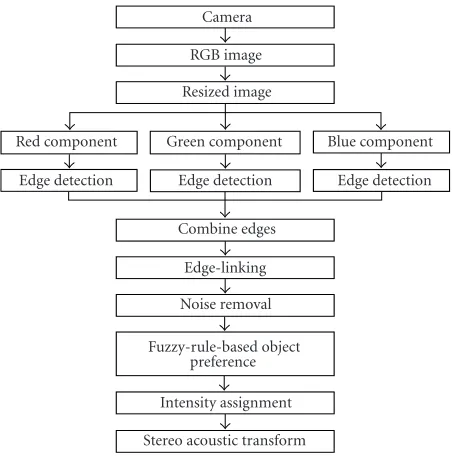
In Figure 2, the block diagram of the proposed image processing methodology is shown. The captured colour im-age is resized to 32×32 [6]. The reason for selecting 32×32 size is mainly to achieve the smallest real-time image process-ing without compromisprocess-ing the quality of objects in the image plane. This selection of resizing is also important in restrict-ing the amount of information that human ear can assimi-late per second. Canny edge detector is used to detect edge locations in three-colour components in RGB image and the results are combined to give overall edges of the image. A method of edge-linking is proposed to combine the broken edges and the edges at the boundary of images. Unnecessary edges are removed using a noise removal procedure. Region inside the closed edges are considered as objects. Fuzzy rules are applied to assign a preference to the identified objects. Each of these processing steps is discussed in detail in the fol-lowing sections.
3.1. Edge detection
Edge detection is one of the most important human vision properties. Often human identifies the object with its bound-aries and shape. The goal of edge extraction is to provide useful structural information about object boundaries. From the edges, the object properties such as area, perimeter, and shape can be measured for object identification [7]. Lapla-cian, Roberts, Sobel, and Prewitt are some of the edge de-tector operators [8]. These operators can detect edges by us-ing convolution masks that represent the “ideal” edge step in various directions. The main disadvantages of these opera-tors are their scale dependence and noise sensitivity. Canny edge detector is one of the optimum edge detecting meth-ods for step edges corrupted by white noise [9]. Canny edge detector has better performance in edge detection than the other methods. In the earlier image processing methodol-ogy of NAVI system, the boundary of objects is detected us-ing a neural network-based Canny edge operator. The size of the filter, threshold, and the ratio of threshold are derived by applying a feed-forward neural network. In some cases, the edge detectors applied to greyscale image do not pro-vide enough information in identifying a meaningful object. Many researchers have extended their attention to colour im-age processing since more edge information can be extracted from colour images [10,11].
In this work, an attempt is made to use colour informa-tion for edge detecinforma-tion in NAVI system. Generally the edge detection method on colour images can be classified into three categories. First, the edges are detected in each colour channel (e.g., R, G, and B components), respectively. The re-sults are then combined. Second, edges are detected in the lu-minance channel only. Third, edges are detected based on the gradient in the three-channel image field [12]. More recently, Wesolkowski et al. examined a comparison of colour edge de-tection performance in several colour spaces [13]. In this pa-per, the edge detection is employed in RGB colour space. The colour image is separated into red component, green com-ponent, and blue component. Canny edge detector is used to determine the edge location of each colour component. Assuming all edges present in each colour component as
Stereo acoustic transform Intensity assignment Fuzzy-rule-based object
preference Noise removal
Edge-linking Combine edges
Edge detection Edge detection Edge detection Red component Green component Blue component
Resized image RGB image
Camera
Figure2: Block diagram of the image processing methodology.
desired edges, they are combined using an “OR” operator. The implemented Canny edge detector has been found ade-quate for NAVI application. However, it is realized that edge detection alone is not enough to extract the object from the image. Further processing is undertaken to identify and con-nect the broken edges to form meaningful objects.
3.2. Edge-linking
Images of real scene naturally contain objects, which are in-complete or distorted by various factors such as the lighting effects and the positioning of the object. Due to these factors, edges in the real images seldom form the closed and con-nected boundaries that are required for the object extraction. An edge-linking process is required to assemble these edges into meaningful edges. Based on the analysis performed in several experiments, the combined edges produce gaps of less than three pixels in the image. As a solution, an edge-linking algorithm is undertaken to connect broken edges with two gaps. The combined edge has to be thinned for preprocess-ing. This is to provide an edge width of one pixel. Each edge is then analyzed in 3×5 neighbourhoods for horizontal direc-tion and 5×3 neighbourhoods for vertical direction. This candidate edge must smoothly connect the broken edges. Figure 3 illustrates the candidate edges for horizontal and vertical directions.
• • •
× × • • • • × ×
• • •
• • • × × • •
• • × × • • •
×
•
Edge derived from Canny edge detector The candidate edge
Figure3: Candidate edges for horizontal and vertical directions.
done for each border to form edges at this border. For the top border, edges in the second row of the image are scanned. If broken edges are found, pixels above the scanned edges are set as foreground. The same method applies for other three borders of the image. After the necessary edge is formed at the border of the image, edges present at the border are con-nected so that a complete object boundary is formed. All edges in the image are labelled to ensure that only edges with the same label will be connected. Once the edges are labelled, each edge in the image border matrix is scanned. Starting at the first scanned edge, the next edge is located and identified as the end edge if it has the same label with the first edge. Each pixel between the two scanned edges is presumed to belong to a straight edge segment and this pixel is set to foreground. If there are more than two edges with the same label present at the border, the process is omitted.
3.3. Noise removal
The goal of noise removal is to remove the extraneous edges present in the image without affecting the desired objects. Some basic morphological operations are used in this stage. Morphology is a technique for extracting image components, which are useful for region shape representation. In the mor-phological operation, a pixel that has value 0 (off pixel) is considered as background and a pixel that has value other than 0 (onpixel) is considered as foreground. Object is lo-cated as a set of on pixels in an image that form a connected group [14,15]. Region inside the closed edge is identified as an object. Therefore, this region has to be set to foreground. Dilation and erosion operations are undertaken to smooth the object images. A disk structuring element with the size of one pixel is created. This structuring element is used in ero-sion operation to remove one pixel from around the bound-ary of all objects. As a result, the extraneous edges present in the image will be eliminated and the objects will shrink. To restore the objects to their original size, dilation operation is applied to the eroded objects using the same structuring element.
3.4. Fuzzy-rule-based object preference
The fundamental task involves in this stage the determina-tion of the object of interest in the enhanced image. Usually in the industrial machine vision, objects of interest are found by evaluating certain object features such as size, colour,
Outside iris area region
Iris area region
Figure4: The “iris area” and the “outside iris area” of the image.
texture, and position. The object of interest and its features information are known and specified before the recognition task can be performed [16]. On the other hand, the selec-tion of object of interest for a blind navigaselec-tion applicaselec-tion is uncertain and time varying. This is due to the constant shift-ing of the headgear-mounted camera orientation by the blind people. Significant difficulties arise as the features of objects in their environment keep on changing as the blind person moves and thus it is not possible to identify the object of in-terest by evaluating the fixed object feature. To resolve these uncertainties, certain properties are taken into consideration. One of the considerations is the creation of a new parame-ter for objects in the enhanced image. The parameparame-ter chosen here is the preference of the object. The object preference acts as a guidance to blind people to determine object of interest in the image. Moreover, by having different preferences, the blind user can easily discriminate the object properties in the environment.
To simplify the recognition task as well as to avoid confu-sion to the blind user, the preference levels to be assigned to objects in the image should be in small number. In this work, three preferences are set: the high preference, the medium preference, and the low preference. The high preference level indicates that the object is highly preferred and it is the ob-ject of interest in the image. Obob-ject with the medium or small preference level indicates that the object is less pre-ferred than the object of interest but still has importance for navigation purposes. To compute the preferences of object, fuzzy-rule-based system is employed. Since many of the ba-sic concepts in recognition task are ambiguous in nature and cannot be defined precisely, the fuzzy-rule-based system ap-pears to be a good choice to deal with such uncertainty is-sues.
area of the image.Figure 4illustrates the image used in this paper and the region of iris area and the region outside iris area. Each input feature is expressed using three membership functions namely small, medium, and big. The membership functions such as small and big are expressed using trape-zoidal curve. For medium membership, a triangular curve is used. The output, object preference O, has three triangular curve memberships.Table 1shows the inputs and the output of the fuzzy-rule-based system. The defuzzification is per-formed using centroid method.
A total of 27 rules are derived for this system. The rules are based on certain observations such as human visual con-sideration and also from the experience with the blind per-son. Since NAVI system is to be used by human blind, it is necessary to consider human preference regarding the selec-tion of object of interest in the image. The first property is that if human concentrates on a particular object, other ob-jects that surround the object of interest has less preference. The background goes a little out of concentration and hence is less focused. If there is only one object in the scene, the ob-ject would be detected as high-preference obob-ject regardless of the size and the position of that object. The objects can be detected before the object features are extracted. For this condition also, it is not important to evaluate the attributes of object features. Thus this condition can be directly evaluated without using the fuzzy-rule-based system.
The second property is based on the fact that the image in the real world usually contains more than one object. For this property, the fuzzy-rule-based system is essential to eval-uate the attributes of object features. To provide a collision-free navigation system, the size and the location of object are considered as important features. In this case, a bigger object is more important than a smaller object. Apart from that, the object which is located at the centre of sight is consid-ered more important than objects which are located away from the centre of sight. Another important note is that as the blind person gets nearer to any object, the size of object gradually becomes larger. All the above discussed conditions are taken into consideration while developing the fuzzy rules. Some of the fuzzy rules are given as follows.
(i) Rule 1. If I1is small, I2is small, and I3is small, then O is low.
(ii) Rule 3. If I1is small, I2is small, and I3is big, then O is high.
(iii) Rule 10. If I1 is medium, I2 is small, and I3 is small, then O is low.
(iv) Rule 11. If I1is medium, I2is small, and I3is medium, then O is medium.
(v) Rule 19. If I1is big, I2is small, and I3is small, then O is medium.
(vi) Rule 21. If I1is big, I2is small, and I3is big, then O is high.
3.5. Intensity assignment
The result of the fuzzy-rule-based system produces three out-puts which are low, medium, and high preferences. These
Table1: Inputs and output of fuzzy-rule-based object preference.
Variable Membershipfunction
Small Object size I1 Medium
Big Small Input Pixel distribution outside iris area I2 Medium
Big Small Pixel distribution inside iris area I3 Medium
Big Low Output Object preferences O Medium
High
outputs are referred for assigning the objects with different grey intensities. Dark grey intensity is assigned for a low-preference object. A medium-low-preference object is shaded into light grey intensity and a high preference into white in-tensity.
3.6. Testing
In experimentation, 200 colour images have been tested to evaluate the proposed methodology. The testing is done of-fline and online. The result of each proposed stage in im-age processing methodology is shown inFigure 5. Figures5a and 5bshow the results of proposed methodology for in-door images. In Figure 5a, four objects with different sizes are shown. The respective fuzzy output images are shown in the sixth column. From the output, one object is highlighted with high intensity and others with low intensity.Figure 5b shows another indoor image. In this figure, three objects can be detected and object in the centre of image has high prefer-ence. Other objects have low preferences. Figures5cand5d illustrate the results of proposed methodology using outdoor images. InFigure 5c, only one object is detected and its edges are shown in third column. Using the edge detection, the line on the floor is also detected. By eliminating the extra edges and enhancing the object region, the output image shows only the object and the background. Since only one object is detected, this object is highlighted with high-level intensity. InFigure 5d, there is one object in the centre of image and the other at the left side of the image. The edge image pro-duces complex edges due to the colour pattern on the floor. However by eliminating edges and enhancing the object re-gion, the shape and size of the objects can be inferred. Using the fuzzy rules, the object in the centre of image is given a high preference and the other a lesser preference.
4. STEREO ACOUSTIC TRANSFORMATION
Input image Resized image Edges Edges linking Noise removed Fuzzy output
(a)
(b)
(c)
(d)
Figure5: Results of the proposed methodology.
audible range is from 20 Hz–20 kHz. It is reported, however, that the human auditory is more sensitive in frequency range of 20 Hz–4000 Hz [17]. Since the human auditory system is more sensitive for discrimination in the low-frequency range rather than the high-frequency range, the frequency band is selected to be in the lower side of the frequency range. The vertical position of the image pixel is inversely related to pitch and the pixel intensity is converted into loudness of the sound. The frequency variations in the vertical position are designed to be audibly differentiable. The range of frequency for the sine wave sound generator is set atFL =150 Hz and
FH = 4000 Hz. This range and increment of frequency are
selected by one of the blind volunteers so that he/she is com-fortable with the repeated sound without the deterrence of the environmental sounds. Such specification seems to be fit-ting to other volunteers as well.
Let
(i) f0be the fundamental frequency of the sound genera-tor,
(ii) Ga constant gain,
(iii) FDthe frequency difference between the adjacent pix-els in vertical direction.
The changes in frequency corresponding to (i,j)th pixel in the 32×32 image matrix is given by
FD= fi−fi−1, (1)
where “i” is the row number= 1, 2, 3,. . ., 32. fi is the fre-quency of the sine wave for pixels in row “i” and is repre-sented by
fi=FL+GFL(32−i). (2)
In the proposed system, the frequency is linearly varied by maintainingFDas a constant.
The generated sound pattern is hence given by
S(j)=
32
i=1
Ip(i,j) sinω(i)t; j=1, 2,. . ., 16, (3)
where
(i) S(j) is the sound pattern for column jof the image, (ii) t=0,. . .,D, whereDdepends on the total duration of
the acoustic information for each column of the image, (iii) ω(i)=2π fi, where fiis the frequency corresponding
to row,i.
(a) (b)
Figure6: Examples of simulated images and the description of their sound patterns. (a) Low-frequency band of sound signals only in the right earphone; left earphone has no sound signal. (b) High-frequency band of sound signals for rectangle in the left earphone with higher amplitude and with a time lag from the start of sound. High-frequency band of sound signals for circle in the right ear-phone with lower amplitude. High-amplitude low-frequency sig-nals for bottom rectangle in both the earphones for full duration.
5. TRAINING
The developed scheme of stereo acoustic transform was tested on a visually handicapped volunteer. The sound pat-terns from the real-time images are initially complex to un-derstand and to categorize. For example, in learning Braille codes, the blind individuals have to undergo intensive and systematic courses. In a similar way, to start with the training of sound from the NAVI, it would be appropriate to first train the blind user with simulated images. The training procedure should create an interest and involvement in the blind vol-unteers. They should feel more and more confident as they put in more attention towards using the system. As a sys-tematic procedure, the blind volunteer is first trained with the sound produced by the simulated images developed in Microsoft Windows paint. Initial training is started with the shapes like square, triangle, circle placed in different hori-zontal and vertical orientations in the image frame. The blind volunteer was asked to carefully listen to the sound. The logi-cal meaning such as the shape of objects and their orientation in the image frame were explained to them in each training session.Figure 6shows some simple simulated images with corresponding sound descriptions used in the initial stages of training.Figure 7shows a set of test images with correspond-ing sound descriptions used for later stages of traincorrespond-ing.
After a good level of training, the blind volunteers were able to identify complex simulated images, the objects in in-door environment and the objects in simple outin-door envi-ronment. The volunteers were able to walk along the corridor with restricting obstacles. Slowly moving objects and their directions of motion were also inferred by the blind with the sound produced from the NAVI system. For understanding complex outdoor environments from routine life, the blind need continuous training and a long experience with the sys-tem. The efficiency of the blind in perceiving the objects is found to be increasing with continuous training. In this re-search, information regarding depth of the object is not con-sidered, and it can be developed using stereo cameras. How-ever in the single camera NAVI, by comparing the sound pat-terns from relative distances between the blind person and the object, information regarding distance of objects can be manipulated by the blind person with experience.
(a) (b)
Figure7: Examples of real-life images and the description of their sound patterns. (a) A band of medium-to-low frequency of sound with low amplitude from the left earphone, followed with a band of high-frequency sound with lower amplitude. A band of high-to-medium frequency sound with low amplitude from right earphone, followed with a band of medium-to-low frequency band with high amplitude. A band of high-frequency sound signal with low ampli-tude is inferred in the second half of time duration. (b) A band of high-to-medium frequency sound signals in the left earphone with lower amplitude in the first half of time duration. This is followed with a band of low-frequency sound signal with high amplitude un-til the end of time duration. A band of high-to-medium frequency with high amplitude sound signals in the right earphones in the sec-ond half of the time duration.
6. CONCLUSION
The main objective of this paper is to identify objects in a captured image. Objects are identified by their closed bound-aries. Several approaches of object extraction involved in this paper include the edge detection, the edge-linking, and the noise removal. Once the objects are extracted, a fuzzy rule base is implemented for object identification. In human vi-sion system, often the object of interest is located at the cen-tre of the sight. The proposed fuzzy-rule-based methodology provides a preference to each object in the image. The pro-cessed image is sonified using a stereo sound procedure. The developed sonification procedure was tested on visually handicapped volunteers. With continuous training, the blind user can identify the location of objects through the sound pattern produced from the processed image.
REFERENCES
[1] “World Sight Day: 10 October”, World Health Orga-nization, http://www.who.int/mediacentre/releases/pr79/en/ print.html.
[2] F. Wong, R. Nagarajan, S. Yaacob, A. Chekima, and N.-E. Belkhamza, “Electronic travel aids for visually impaired—a guided tour,” inProc. Conference in Engineering in Sarawak, pp. 377–382, Sarawak, Malaysia, May 2000.
[3] P. B. L. Meijer, “An experimental system for auditory image representations,”IEEE Trans. Biomed. Eng., vol. 39, no. 2, pp. 112–121, 1992.
[4] D. Dewhurst, “The Vuphonics home page,” 2001, http:// www.users.waitrose.com/∼daviddewhurst/Projects.html. [5] P. Picton and M. Capp, The Optophone: Some question and
answer, School of Technology and Design. Nene - Univer-sity College Northampton, 2000,http://oldweb.northampton. ac.uk/aps/eng/research/optophone/optophone.html. [6] G. Sainarayanan, R. Nagarajan, and S. Yaacob, “Vision
[7] J. R. Parker,Algorithms for Image Processing and Computer Vi-sion, John Wiley & Sons, New York, NY, USA, 1997.
[8] R. C. Gonzalez and R. E. Woods, Digital Image Processing, Prentice-Hall, Upper Saddle River, NJ, USA, 2nd edition, 2002.
[9] J. Canny, “A computational approach to edge detection,”IEEE Trans. Pattern Anal. Machine Intell., vol. 8, no. 6, pp. 679–698, 1986.
[10] P. Garcia, F. Pla, and I. Garcia, “Detecting edges in colour im-ages using dichromatic differences,” inProc. 7th International Conference on Image Processing and Its Applications, vol. 1, pp. 363–367, Manchester, UK, July 1999, (Conf. Publ. no. 465). [11] G. Bellaire, K. Talmi, E. Oezguer, and A. Koschan, “Object
recognition: obtaining 2-D reconstructions from color edges,” inProc. IEEE Southwest Symposium on Image Analysis and Interpretation (SSIAI ’98), pp. 192–197, Tucson, Ariz, USA, April 1998.
[12] E. Saber, A. M. Tekalp, and G. Bozdagi, “Fusion of color and edge information for improved segmentation and edge link-ing,” inProc. IEEE Int. Conf. Acoustics, Speech, Signal Process-ing (ICASSP ’96), vol. 4, pp. 2176–2179, Atlanta, Ga, USA, May 1996.
[13] S. Wesolkowski, M. E. Jernigan, and R. D. Dony, “Compari-son of color image edge detectors in multiple color spaces,” in Proc. IEEE International Conference on Image Processing (ICIP ’00), vol. 2, pp. 796–799, Vancouver, BC, Canada, September 2000.
[14] The MathWorks Inc., Image Processing Toolbox, User’s Guide Version 3, 2001.
[15] J. C. Russ,The Image Processing Handbook, CRC Press, Boca Raton, Fla, USA, 2nd edition, 1995.
[16] R. Jain, R. Kasturi, and B. G. Schunck, Machine Vision, McGraw-Hill, New York, NY, USA, 1995.
[17] C. Capelle, C. Trullemans, P. Arno, and C. Veraart, “A real-time experimental prototype for enhancement of vision re-habilitation using auditory substitution,”IEEE Trans. Biomed. Eng., vol. 45, no. 10, pp. 1279–1293, 1998.
R. Nagarajanreceived his B.E. degree (hon-ors) in electrical and electronics engineer-ing from Madras University in 1961, the M. Tech. degree in control engineering from IIT Kanpur in 1969, and the Ph.D. degree in adaptive control from Madras Univer-sity in 1977. Currently he is a Professor in the School of Engineering and Informa-tion Technology, Universiti Malaysia Sabah, Malaysia. His current research interests
in-clude robot control and intelligent process control. He is a Life Fel-low of Institution Engineers, India, a Senior Member in IEEE, USA, and a Member of UICEE, Australia.
G. Sainarayanan is currently a Lecturer in electrical and electronics engineering in Universiti Malaysia Sabah, Malaysia. He re-ceived his B.E., M.E., and Ph.D. degrees, respectively, from Annamali University, In-dia, Bharathiar University, InIn-dia, and Uni-versiti Malaysia Sabah, Malaysia, in 1998, 2000, and 2002. His research interests are in the areas of vision rehabilitation, medical imaging, and intelligent control.
Sazali Yaacob received his B.E. degree in electrical engineering from Universiti Malaya in 1986, the M.S. degree in system engineering from the University of Surrey in 1987, and Ph.D. degree in control en-gineering from the University of Sheffield in 1995. Currently he is a Professor in the School of Mechatronic Engineering, North-ern Malaysia University College of Engi-neering, Malaysia. His research interests
in-clude acoustics, modeling, and control. He was granted a Charted Engineer status by the Engineering Council, United Kingdom, in 2004.