Volume 2007, Article ID 20463,7pages doi:10.1155/2007/20463
Research Article
Power Efficiency Improvements through Peak-to-Average
Power Ratio Reduction and Power Amplifier Linearization
Ning Chen,1G. Tong Zhou,2and Hua Qian3
1Freescale Semiconductor, Inc., Austin, TX 78729, USA
2School of Electrical and Computer Engineering, Georgia Institute of Technology, Atlanta, GA 30332, USA 3Marvell Semiconductor, Inc., Santa Clara, CA 95054, USA
Received 9 June 2005; Revised 14 February 2006; Accepted 24 November 2006
Recommended by Enis Ahmet Cetin
Many modern communication signal formats, such as orthogonal frequency-division multiplexing (OFDM) and code-division multiple access (CDMA), have high peak-to-average power ratios (PARs). A signal with a high PAR not only is vulnerable in the presence of nonlinear components such as power amplifiers (PAs), but also leads to low transmission power efficiency. Selected mapping (SLM) and clipping are well-known PAR reduction techniques. We propose to combine SLM with threshold clipping and digital baseband predistortion to improve the overall efficiency of the transmission system. Testbed experiments demonstrate the effectiveness of the proposed approach.
Copyright © 2007 Ning Chen et al. This is an open access article distributed under the Creative Commons Attribution License, which permits unrestricted use, distribution, and reproduction in any medium, provided the original work is properly cited.
1. INTRODUCTION
Modern transmission formats, such as orthogonal frequen-cy-division multiplexing (OFDM) and code-division mul-tiple access (CDMA), have gained tremendous popularity thanks to their high spectral efficiency. However, a drawback is the low power efficiency of these systems. OFDM and CDMA signals suffer from high peak-to-average power ra-tios (PARs), making them susceptible to nonlinearities that are inherent in the RF/microwave power amplifiers (PAs). To avoid nonlinear distortions, the average operating power of the PA has to be backed-offsignificantly, giving rise to low DC to RF conversion efficiency.
PA efficiency enhancement is a critical issue for wireless communication applications. In a typical cellular base sta-tion, the RF PA and its associated cooling equipment are re-sponsible for approximately 50% of the overall DC power consumption and 60% of its physical size [1]. On the other hand, it is reported that in today’s cellular phones, over 90% of the power used to transmit the signal is wasted in the form of heat that stays inside the phone [2]. The topic of power efficiency has attracted much attention in recent years.
There are two key factors that contribute to the low PA efficiency in these applications: (i) high PAR value of the sig-nal, and (ii) nonlinearity of the PA. Many techniques have been proposed to reduce the PAR, such as deliberate
clip-ping, complementary coding, selected mapping (SLM), and so forth [3–5]. Among the many PA linearization techniques, adaptive digital baseband predistortion is the most cost-effective [6]. To the best of our knowledge, few references except for [7,8] have discussed joint PAR reduction and PA linearization. In [7], the authors investigated the BER per-formance degradation due to inaccuracy of the side infor-mation of the PAR reduction in a multicarrier CDMA sys-tem, but gave no details of PA linearization. In [8], a com-mercial chip that implements deliberate clipping was used as the PAR reduction preprocessor and a lookup table was used for PA linearization. In this paper, we will (i) delineate the relationship between PAR reduction and PA lineariza-tion with respect to their contribulineariza-tions to power efficiency improvements; (ii) propose a modified SLM with threshold-ing and clippthreshold-ing technique and present a closed-form expres-sion for the distribution of the PAR of the resulting signal; (iii) quantify the power efficiency enhancement in terms of increase in the average transmit power while keeping the ad-jacent channel power ratio (ACPR) fixed. We will demon-strate our approach through testbed experiments.
2. POWER EFFICIENCY IMPROVEMENT CONCEPTS
Consider the input-output characteristic of a PA shown in
Output
po
w
er
Input power
Psat
Pi1 Pm1
(a) Nonlinear PA with input backoff. PAR1 (dB) =
Pm1(dB)−Pi1(dB).
Output
po
w
er
Input power
Psat
Pi2 Pm2
(b) Ideal linear PA. PAR2 (dB) = Pm2(dB)−Pi2(dB).
PAR2=PAR1.Pm2>Pm1,Pi2>Pi1.
Output
po
w
er
Input power
Psat
Pi3 Pm3
(c) After PAR reduction. PAR3(dB)=Pm3(dB)−Pi3(dB).
PAR3<PAR2.Pm3=Pm2,Pi3>Pi2.
Output
po
w
er
Input power
Psat
Pi4 Pm4
(d) Allow occasional saturation (clipping). PAR4(dB) =
Pm4(dB)−Pi4(dB). PAR4=PAR3.Pm4>Pm3,Pi4>Pi3.
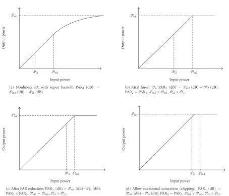
Figure1: PA linearization and PAR reduction can improve the PA efficiency by reducing the amount of backoffthat is needed. From (a)–(d), the average input powerPi4>Pi3>Pi2>Pi1.
the baseband PA output byy(t), thenPsatis the maximum
output power that the PA is capable of producing, that is, Psat = maxt|y(t)|2. Denote by Pm the maximum input power, that is,Pm=maxt|x(t)|2, and byPithe average input power, that is,Pi = E[|x(t)|2]. The peak-to-average power ratio (PAR) is a characteristic of the input signal and is de-fined as PAR(s(t))=Pm/Pi[11] or PAR (dB)=Pm(dB)− Pi(dB).
For a givenPsatand gain of the PA, the efficiency of the
PA increases with increasingPi. InFigure 1(a), the PA is lin-ear up toPm1, but is nonlinear afterwards. Nonlinearity
gen-erates in-band distortion as well as adjacent channel interfer-ence. To avoid these detrimental nonlinear effects, the input signal is often backed-offto the PA’s linear region as shown in
Figure 1(a). The corresponding power efficiency is very low, often in the range of 10% or much less [9]. With PA lin-earization, we strive to achieve anideallinear input-output characteristic shown inFigure 1(b). The input signal is am-plified undistorted untilPsatis reached. InFigure 1(b), the
average input power is higher than that inFigure 1(a), that
is, Pi2 > Pi1, demonstrating how power efficiency can be
improved via PA linearization. If we can reduce the PAR of the input signal as well, we arrive at a situation depicted in
Figure 1(c). The peak power is the same as inFigure 1(b), but thanks to PAR reduction, the average input power is increased, that is,Pi3 > Pi2, further boosting the efficiency
of the PA. If we drive the PA harder by scaling up the input so the signal occasionally enters the saturation region of the PA (seeFigure 1(d)), we can achieve even higher efficiency at the expense of controllable nonlinear distortions.
3. PAR REDUCTION
3.1. Threshold on PAR
Denote by{Sl[k]}kN=−01thelth block of the frequency-domain
OFDM signal drawn from a known constellation, whereN
is the number of subcarriers. For the rest of the paper, we will drop the block indexl for notational simplicity, since OFDM can be free of interblock interference with proper use of the cyclic prefix. The corresponding time-domain signal is
s(t)=(1/√N)Nk=−01S[k]ej2πkt/Ts, 0≤t≤Ts, whereTsis the
OFDM symbol period and j=√−1.
The worst possible PAR of an OFDM signal isN (e.g., whenS[k] is the same for eachk). To amplifys(t) absolutely without any distortion, we need to position the highest pos-sible peak power atPm2inFigure 1(b). Under this
arrange-ment, the average powerPi2and thus the PA efficiency will
be very low.
In practice, a PA is expected to provide a certain level of power efficiency, which means that for a given PA and bias-ing conditions, the average input powerPihas to be above a certain amount. This also requires the input signal PAR to be less than a thresholdγ0. The concept of PAR thresholding
was also explored in [10] for the partial transmit sequence technique.
3.2. Review of selected mapping for OFDM
The complementary cumulative distribution function (CCDF) of the PAR of the continuous-time s(t) was sug-gested in [12]
PrPARs(t)> γ=1−exp
−e−γN
π
3lnN . (1)
Selected mapping (SLM) was first proposed in [5] as a distortionless technique to reduce the PAR of OFDM sig-nals. Assume that an i.i.d. phase table {φ(m)[k]}1≤m≤M
0≤k≤N−1 is
available at the transmitter and at the receiver. Let us first rotate the phases ofS[k] to obtainS(m)[k] = S[k]ejφ(m)[k]
. From among theMequivalent time-domain representations,
{s(m)(t)}M
m=1,s(m)(t), which has the lowest PAR, is
transmit-ted, that is, PAR(s(m)(t))=min
1≤m≤MPAR(s(m)(t)). Optimal design of the phase table {φ(m)[k]}1≤m≤M
0≤k≤N−1
has been investigated in [13]: the PAR reducing capability of SLM is maximized when {φ(m)[k]} are i.i.d. satisfying
E[ejφ(m)[k]
] =0. Under this optimality condition, the time-domain signalss(m)(t) ands(l)(t) can be shown to be
asymp-totically independent form=l. Consequently, for a largeN, we can obtain the CCDF of the SLM-OFDM signals(m)(t) as
follows:
PrPARs(m)(t)> γ=[1−a]M, (2)
wherea=exp{−e−γN(π/3) lnN}(cf. (1)).
We make the following remarks regarding the “conven-tional” SLM described above.
(1) SLM aims at minimizing the PAR per OFDM block by carrying out allM mappings. Even if the first few mappings have already managed to reduce the PAR to be below a certain thresholdγ0, the SLM scheme still
continues to seek further reduction of the PAR. (2) For givenNandγ0values, (2) shows that even after all
Mmappings are tried out, there is still a nonzero prob-ability that the SLM method fails to meet the PAR goal, that is, the resulting PAR(s(m)(t))> γ
0. When that
hap-pens,s(m)(t) will need to be clipped to meet the peak
power and average power constraints.
(3) For given N and M values and clipping probability
p =Pr{PAR(s(m)(t)) > γ
0}, we can find from (2) the
corresponding PAR threshold
γ0=ln
N
π
3 lnN
−ln
ln 1
1−p1/M
. (3)
We investigate next a modified SLM technique which incorporates the above PAR thresholding and clipping con-siderations.
3.3. SLM with thresholding and clipping
Our objective here is to apply SLM, but to stop trying as soon as the PAR thresholdγ0 is met, with the constraint that the
number of trials is no more thanM(including the original OFDM signal). Our strategy is “to do only what is necessary” in order to save computational resources. As mentioned be-fore, there is always the possibility that even after allMtrials, SLM still fails to meet the PAR goalγ0. In that case,s(m)(t)
is clipped to become x(t), which has maximum amplitude
Piγ0(the clipping level). As long as the clipping probability
(2) evaluated atγ0is small (e.g., 10−3), there will be negligible
amount of spectral regrowth or BER increase.
The step-by-step algorithm for the proposed SLM with thresholding and clipping (SLMTC) technique is described inAlgorithm 1.
In [14], SLM was proposed to reduce the PAR of the forward link CDMA signal using random phase and PN offset mapping. The concept of thresholding and clipping de-scribed above is not restricted to any specific signal format; for example, it can be applied to the CDMA system as well.
We note that combining SLM with threshold clipping is not merely doing both; the SLM algorithm exits if the predetermined PAR threshold is met. PA linearization oper-ates independently of PAR reduction however, as we elabo-rated inSection 2.
3.4. Performance analysis of SLMTC
We analyze here the CCDF expression for the PAR of the SLMTC signalx(t) obtained as described in the previous sec-tion. Denote bys(m)(t) the signal after SLM with
threshold-ing, which isnotto be confused with thes(m)(t) notation used
in the conventional SLM (cf.Section 3.2). Ifγ≤γ0, the event
Step 1. Setm=m=1.
Step 2. Forms(m)(t) and compute PAR(s(m)(t)).
Step 3. If PAR(s(m)(t))≤γ
0, then continue toStep 4; else go toStep 5.
Step 4. Setm=mandx(t)=s(m)(t), and go toStep 8.
Step 5. If PAR(s(m)(t))<PAR(s(m)(t)), then go toStep 5.1; else go toStep 5.2.
Step 5.1. Setm=m.
Step 5.2. m=m+ 1.
Step 6. Ifm > M, then go toStep 7; else go toStep 2.
Step 7. Clips(m)(t) to form (A=Piγ 0)
x(t)= ⎧ ⎨ ⎩
s(m)(t) ifs(m)(t)≤A,
Aexpj∠s(m)(t) otherwise. (4)
Step 8. Transmitx(t).
Algorithm1: SLM with thresholding and clipping.
which in turn is equivalent to the event
∃1≤d≤M, such that PARs(d)(t)≤γ,
PARs(l)(t)> γ 0
d−1
l=1.
(5)
By recalling (1), we obtain
PrPARx(t)≤γ
=
M
d=1
PrPARs(d)(t)≤γ
d−1
l=1
PrPARs(l)(t)> γ 0
=
M
d=1
a1−a0
d−1
= a a0
1−1−a0
M
, forγ≤γ0,
(6)
wherea0=exp{−e−γ0N
(π/3) lnN}. Obviously due to clipping,
PrPARx(t)> γ=0, forγ > γ0. (7)
Combining (6) and (7), we find the CCDF of the PAR for the proposed SLMTC method:
PrPARx(t)> γ= ⎧ ⎨ ⎩
1− a a0
1−1−a0
M
, γ≤γ0,
0, γ > γ0.
(8)
10−5
10−4
10−3
10−2
10−1
100
Pr
(P
A
R
>γ
)
4 5 6 7 8 9 10 11 12 13 14
γ(dB) Empirical (OFDM) Theoretical (OFDM) Empirical (SLM-OFDM)
Theoretical (SLM-OFDM) Empirical (SLMTC-OFDM) Theoretical (SLMTC-OFDM) w/SLMTC
w/SLM
OFDM PAR reduction
3.5 dB
Figure2: CCDF of the PAR for the OFDM signal, OFDM signal with SLM, and OFDM signal with SLMTC.
3.5. Validation of the CCDF expressions
In the computer simulations, the number of subcarriers
N = 128, the maximum number of phase rotations M =
16, and the PAR threshold γ0 = 7.5 dB. The
frequency-domain OFDM subsymbols were drawn independently from a QPSK constellation, and 106Monte Carlo runs were
per-formed. Figure 2shows the empirical CCDFs (solid lines) of PAR(s(t)) (OFDM), PAR(s(m)(t)) (SLM), and PAR(x(t))
(SLMTC), along with the corresponding theoretical CCDFs (dash-dotted lines) calculated from (1), (2), and (8), respec-tively. The empirical CCDFs of the continuous-time PAR were obtained by evaluating the discrete-time PAR of the 4-time oversampled OFDM signal [11]. It is evident from
Figure 2that the theoretical and the empirical CCDFs agreed very well. We observe that whenM=16, the proposed algo-rithm achieved 3.5 dB of PAR reduction at the CCDF level of 10−3. Indeed, if we substitute N = 128 and p = 10−3
into (1), we obtain γ = 12.5720 ∼= 11 (dB); if we substi-tute N = 128, M = 16, and p = 10−3 into (3), we
ob-tain γ0 = 5.6178 ∼= 7.5 (dB). Thus, PAR reduction in the
amount ofγ−γ0=3.5 dB was achieved at the CCDF level of
p=10−3.
We observe fromFigure 2that the CCDF curves for SLM and SLMTC cross over atγ0, and SLMTC has less PAR
re-ducing capability than SLM forγ < γ0. This is completely
expected since by design, SLMTC generally uses fewer map-pings and consumes less computational resources than SLM. Unless one pursues block-by-block adaptive biasing or linear scaling [15] approaches, any PAR value lower than the re-quiredγ0does not necessarily lead to additional power
Digital output (64 M memory)
High-speed digital I/O
system
Digital input (64 M memory)
14-bit 120 MSPS
DAC
LO1 LO2
DUT
12-bit 120 MSPS
ADC
DSP
Figure3: Block diagram of the testbed.
PAR thresholding can be harvested using a buffered dynamic processing scheme [16], which results in a smaller transmis-sion latency than SLM, and thus permits a higher data rate.
4. DIGITAL BASEBAND PREDISTORTION LINEARIZATION OF THE PA
We adopt the memory polynomial predistorter (PD) model given by [6]
z[n]=
K
k=1
Q
q=0
akqx[n−q]x[n−q]k−1, (9)
wherex[n]=x(t)|t=n/Fsis the sampled version of the input x(t) with sampling frequency Fs, z[n] is the discrete-time output of the PD, and{akq}are the PD coefficients. This PD has memory depthQand highest nonlinearity orderK. The indirect learning architecture is used to solve for the param-eters{akq}via linear least squares; see [6] for details. Note that whenQ=0, (9) becomes a memoryless polynomial PD, which may be sufficient for memoryless PAs, such as handset PAs with narrowband inputs.
5. TESTBED EXPERIMENTS
We have conducted testbed experiments on two different PAs to demonstrate our approach. Our goal is to show that for the same PA, it is possible to boost the average transmit power through PAR reduction and PA linearization, while keeping the ACPR unchanged.
Figure 3depicts the configuration of the testbed, which consists of a high-speed digital I/O system, a digital-to-analog converter (DAC), RF transmit and receive chains, a device under test (DUT), and an analog-to-digital converter (ADC). The high-speed digital I/O system has 150 million
samples per second (MSPS), 16-bit digital input/output ca-pability. In the transmission mode, the digital I/O system first generates baseband data, applies the SLMTC algorithm, pre-distorts it, and then digitally upconverts the signal to an in-termediate frequency (IF) of 30 MHz, and finally sends out the 14-bit data stream to the DAC at a sampling rate of 120 MSPS. Superheterodyne upconversion and downconver-sion chains are used to convert the digital IF signal to and from the carrier frequency. The DUTs are, respectively, a 1 W handset PA and a 45 W base-station PA. In the acquisition mode, the digital I/O system acquires 12-bit digital IF data at the sampling rate of 120 MSPS from the ADC. The received baseband data y[n] is obtained by converting the PA output to baseband and removing the time delay between the input and the output of the digital I/O system. Since the signal is modulated in the digital domain, any inphase and quadra-ture imbalance problem in the quadraquadra-ture modulator is ob-viated.
5.1. Experiment on the 1 W handset PA
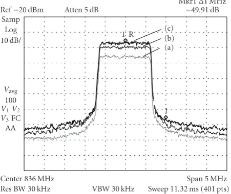
In this experiment, the DUT is the 1 W handset PA. The in-put is an OFDM signal centered at 836 MHz with a 1.25 MHz bandwidth and 128 subcarriers. We measured the power spectral density (PSD) of the PA output using a spectrum analyzer. ACPR was measured as the ratio between the aver-age power in the adjacent channel and the averaver-age power in the main channel, both over a 30 KHz bandwidth [9]. The requirement was to keep the ACPR below−50 dBc.Figure 4
shows the PSDs of the PA output when (a) the input was backedoffjust enough to meet the ACPR requirement; (b) a memoryless polynomial PD (i.e.,Q = 0,K = 5 in (9)) was applied, and the amount of input backoffwas reduced; (c) both SLMTC (M =16,γ0 = 7.5 dB) and the
Atten 5 dB Ref−20 dBm
Samp Log 10 dB/
Vavg
100 V1V2
V3FC
AA
Center 836 MHz
Res BW 30 kHz VBW 30 kHz
Span 5 MHz Sweep 11.32 ms (401 pts) 1 R
1 (a) (b) (c)
Mkr1Δ1 MHz
−49.91 dB
Figure4: Power spectral density measurements at the output of the 1 W handset PA when (a) the input was backed-off, (b) a memo-ryless polynomial PD (Q =0,K =5) was applied, and (c) both SLMTC (M=16,γ0=7.5 dB) and the memoryless polynomial PD (Q=0,K=5) were applied.
backoff. By comparing curves (a) and (b) inFigure 4, we see that the average output power in the main channel increased by 6 dB thanks to the use of the PD and the resulting reduc-tion in backoff. Moreover, with the SLMTC PAR reduction technique, we were able to boost the average output power by another 3 dB without introducing any spectral regrowth (cf. lines (b) and (c)). Therefore, we have achieved a total of 9 dB increase in the average output power of the PA through the combination of PAR reduction and predistortion lineariza-tion.
5.2. Experiment on the 45 W base-station PA
In this experiment, the DUT is the 45 W base-station PA. The input is an OFDM signal centered at 881 MHz with a 2.5 MHz bandwidth and 128 subcarriers. For the 45 W PA, the requirement was to keep the ACPR below−45 dBc.
Figure 5shows the PSDs of the PA output when (a) the in-put was backed-offjust enough to meet the ACPR specifi-cation; (b) a memory polynomial PD (i.e., Q = 5, K =
5 in (9)) was applied; (c) both SLMTC (M = 16, γ0 =
7.5 dB) and the memory polynomial PD were applied. From
Figure 5, we can see that the average output power was in-creased by 11 dB through the combination of PAR reduction and predistortion linearization. Through experimentation, we have found that this high power amplifier had significant memory effects and that memoryless predistortion was not as effective as the memory polynomial predistortion demon-strated here.
6. CONCLUSIONS
We proposed in this paper joint PAR reduction and PA lin-earization as an effective approach to improve the efficiency
Atten 5 dB Ref−20 dBm
Samp Log 10 dB/
Vavg
100 V1V2
V3FC
AA
Center 881 MHz
Res BW 30 kHz VBW 30 kHz
Span 10 MHz Sweep 22.64 ms (401 pts) 1 R
1 (a) (b) (c)
Mkr1Δ2 MHz
−44.97 dB
Figure5: Power spectral density measurements at the output of the 45 W base-station PA when (a) the input was backed-off, (b) a memory polynomial PD (Q = 5,K = 5) was applied, and (c) both SLMTC (M=16,γ0 =7.5 dB) and the memory polynomial PD (Q=5,K=5) were applied.
of the RF/microwave PA in wireless communications. For PAR reduction, we discussed a thresholding and clipping technique to reduce the computational resource require-ments of selected mapping (SLM). A closed-form CCDF ex-pression was derived for the resulting PAR. For PA lineariza-tion, we adopted the (memory) polynomial predistorter for its simplicity and robustness. PAR reduction and PA lin-earization can be applied independently, so many combina-tions of PAR reduction and PA linearization techniques may work. Using testbed experiments, we demonstrated the eff ec-tiveness of our technique as significant increase in the average output power without exceeding the spectral emission limits. Our analysis uses OFDM as the model system, but the idea of joint PAR reduction and PA linearization applies to other systems characterized by high PAR values as well.
ACKNOWLEDGMENTS
The authors would like to thank Mr. Robert J. Baxley for insightful discussions on the PAR thresholding idea. This work was supported in part by the US National Science Foundation Grants 0218778 and 0219262, the US Army Re-search Laboratory Communications and Networks Collab-orative Technology Alliance Program, and the Texas Instru-ments DSP Leadership University Program.
REFERENCES
[1] A. A. Triolo, “Advanced techniques in high-efficiency power amplification for WCDMA,” inNJIT ECE Seminar, February 24, 2003.
[3] S. M. Ju and S. H. Leung, “Clipping on COFDM with phase on demand,”IEEE Communications Letters, vol. 7, no. 2, pp. 49–51, 2003.
[4] A. E. Jones, T. A. Wilkinson, and S. K. Barton, “Block coding scheme for reduction of peak to mean envelope power ratio of multicarrier transmission schemes,”Electronics Letters, vol. 30, no. 25, pp. 2098–2099, 1994.
[5] R. W. B¨auml, R. F. H. Fischer, and J. B. Huber, “Reducing the peak-to-average power ratio of multicarrier modulation by se-lected mapping,”Electronics Letters, vol. 32, no. 22, pp. 2056– 2057, 1996.
[6] L. Ding, G. T. Zhou, D. R. Morgan, et al., “A robust digital baseband predistorter constructed using memory polynomi-als,”IEEE Transactions on Communications, vol. 52, no. 1, pp. 159–165, 2004.
[7] H.-G. Ryu, T. P. Hoa, K. M. Lee, S.-W. Kim, and J.-S. Park, “Improvement of power efficiency of HPA by the PARR reduc-tion and predistorreduc-tion,”IEEE Transactions on Consumer Elec-tronics, vol. 50, no. 1, pp. 119–124, 2004.
[8] R. Sperlich, Y. Park, G. Copeland, and J. S. Kenney, “Power am-plifier linearization with digital pre-distortion and crest factor reduction,” inProceedings of IEEE MTT-S International Mi-crowave Symposium Digest, vol. 2, pp. 669–672, Fort Worth, Tex, USA, June 2004.
[9] S. C. Cripps,RF Power Amplifiers for Wireless Communications, Artech House, Boston, Mass, USA, 1999.
[10] A. D. S. Jayalath and C. Tellambura, “Adaptive PTS approach for reduction of peak-to-average power ratio of OFDM sig-nal,”Electronics Letters, vol. 36, no. 14, pp. 1226–1228, 2000. [11] J. Tellado, Multicarrier Modulation with Low
PAR—Appli-cations to DSL and Wireless, Kluwer Academic, Dordrecht, The Netherlands, 2000.
[12] S. Wei, D. L. Goeckel, and P. A. Kelly, “The complex enve-lope of bandlimited OFDM signals is asymptotically Gaussian: proof and application,”http://www.ece.lsu.edu/swei. [13] G. T. Zhou and L. Peng, “Optimality condition for selected
mapping in OFDM,”IEEE Transactions on Signal Processing, vol. 54, no. 8, pp. 3159–3165, 2006.
[14] N. Chen and G. T. Zhou, “Distortionless crest factor reduction for forward link CDMA,” inProceedings of the 6th IEEE Work-shop on Signal Processing Advances in Wireless Communications (SPAWC ’05), pp. 294–297, New York, NY, USA, June 2005. [15] H. Ochiai, “Performance analysis of peak power and
band-limited OFDM system with linear scaling,”IEEE Transactions on Wireless Communications, vol. 2, no. 5, pp. 1055–1065, 2003.
[16] H. Qian, C. Xiao, N. Chen, and G. T. Zhou, “Dynamic selected mapping for OFDM,” inProceedings IEEE International Con-ference on Acoustics, Speech and Signal Processing (ICASSP ’05), vol. 4, pp. 325–328, Philadelphia, Pa, USA, March 2005.
Ning Chenreceived his dual B.S. degrees in electronic engineering and in account-ing from the Shanghai Jiao Tong University (SJTU), China, in July 1997. He worked as an Instructor at SJTU until August 2000. He received his M.S. degree in electrical and computer engineering from the New Mexico State University in December 2001. He earned the Ph.D. degree in electrical engineering from the Georgia Institute of
Technology, Atlanta, in 2006. He is currently employed by Freescale Semiconductor, Inc., in Austin, Tx, USA. His general research inter-ests are in the areas of signal processing and communications. Spe-cific current interests include predistortion linearization of non-linear power amplifiers, peak-to-average power ratio reduction of communication signals, communication channel identification and equalization, and adaptive algorithm development on DSP.
G. Tong Zhoureceived her B.S. degree in biomedical engineering and instrumenta-tion from the Tianjin University, China, in July 1989. From September 1989 to May 1995, she was with the University of Vir-ginia (UVA), where she obtained her M.S. degree in biophysics in May 1992, M.S. de-gree in electrical engineering in January 1993, and Ph.D. degree in electrical engi-neering in January 1995. She has been with
the School of Electrical and Computer Engineering at Georgia Tech since September 1995 where she is now a Professor. In 1997, she re-ceived the National Science Foundation Faculty Early Career Devel-opment (CAREER) Award. She is also recipient of the 2000 Meritor Teaching Excellence Award at Georgia Tech. Her research interests are in the general areas of statistical signal processing and commu-nications applications.
Hua Qian received his B.S. and M.S. de-grees in electrical engineering from Tsing-hua University, Beijing, China, in 1998 and 2000, respectively. He received the Ph.D. de-gree in electrical and computer engineer-ing from the Georgia Institute of Technol-ogy, Atlanta, Ga, USA, in 2005. He is cur-rently a Senior Design Engineer at Marvell Semiconductor Inc. His general research in-terests are in the areas of signal