UNIVAC
94BD
sYSTEM
This document contains the latest information available at the time of publication. However, the Univac Division reserves the right to modify or revise its contents. To ensure that you have the most recent information, contact your local Univac Representative.
UN IVAC is a registered trademark of the Sperry Rand Corporation.
Other trademarks of the Sperry Rand Corporation in this publication are:
CONTENTS 1. INTRODUCTION
1.1. UNIVAC 9000 SERIES COMPUTER FAMILY
1.2.
GROWTH.AND COMPATIBILITY1.3. SOFTWARE FEATURES
1.3.1. Modularity
1.3.2.
Multiprogramming1.4.
COMMUNICATIONS1.5.
EQUIPMENT CONFIGURATIONS2. SYSTEM HARDWARE
2.1.
THE UNIVAC 9480 SYSTEM2.2.
CENTRAL PROCESSOR UNIT2.2.1.
Main Storage Characteristics2.2.1.1. Addressing and Data Formats
2.2.1.2.
Low-O rder Sto rage2.2.1.3.
Storage Protection2.2.2.
Control Section2.2.3.
Ari thmeti c Section2.2.3.1.
Binary (Fixed-Point) Arithmetic2.2.3.2.
Decimal Arithmetic2.2.3.3.
Lo gi cal0
perations2.2.4.
Input/Output Section2.2.4.1.
Multiplexer Channel2.2.4.2.
Selector Channel2.2.5.
Interrupt ProceSSing Control2.3.
UNIVAC 9480 SYSTEM INSTRUCTION REPERTOIRE2.3.1.
Supervisor Instruction Set2.3.2.
Standard Instruction Set2.3.3.
Instruction Types2.3.3.1.
Register to Register Instructions (RR)2.3.3.2.
Register to Indexed Storage Instructions (RX)2.4.
CONSOLE2.4.1.
Keyboard Assembly and Control2.4.2.
Printer Assembly and Control2.4.3.
Controls and Indicators2.5.
INPUT/OUTPUT DEVICES2.5.1.
UNIVAC0716
Card Reader Subsystem2.5.2.
UNIVAC0604
Card Punch Subsystem2.5.3.
UNIVAC0768
Printer Subsystem2.5.3.1.
UNIVAC0768-00/01
Printer Subsystem2.5.3.2.
UNIVAC0768-02/03
Printer Subsystem2.5.4.
Data Comm uni cation s Subsystem2.5.4,1.
Line Terminal Controller2.5.4.2.
Line Terminal2.5.4.3.
Communications Interface2.5.4.4.
Asynchronous Timing Assembly2.5.4.5.
Synchronous Timing Assembly2.5.4.6.
Configurations2.5.5.
UNIVAC1004
or1005
Subsystem2.5.6.
UNIVAC9200/9200 11/9300/9300
II Subsystem2.5.7.
UNISERVO Magnetic Tape Subsystem2.5.7.1.
UN ISERVO12/16
Magnetic Tape Subsystem2.5.7.1.1.
UNISERVO12
Magnetic Tape Unit2.5.7.1.2.
UNISERVO16
Magnetic Tape Unit2.5.7.2.
UNISERVO VI-C Magnetic Tape Subsystem2.5.8.
UNIVAC Disc Subsystems2.5.8.1.
UNIVAC8411
Disc Subsystem2.5.8.2.
UNIVAC8414
Disc Subsystem2.5.9.
UN I VA C2703
Opti cal Do cum ent Reader Subsystem2.5.10.
UNIVAC0920
Paper Tape Subsystem2.5.11.
UNISCOPE100
and300
Terminals2.5.12.
UNIVAC OCT500
Data Communications Terminal2.5.13.
UNIVAC OCT1000
Data Communications Terminal2.5.13.1.
Data Buffers2.5.13.2.
Poll ing System3. PROGRAMMING SYSTEMS SUPPORT
3.1.
OPERATING SYSTEM3.1.1.
Sup ervi so r3.1.1.1.
Multiprogramming3.1.1.2.
Timer and Simulated Day Clock Services3.1.1.3.
Shared Routine Coding3.1.1.4.
Operator Communication3.1.1.5.
Transient Area Management3.1.1.6.
Interrupt Handling3.1.1.7.
Input/Output Control System (IOCS)3.1.1.8.
0 i sc Auxi Ii ary Sto rage3.1.2.
Data Management3.1.2.1.
Sequential File Processing3.1.2.2.
Nonsequential File Processing3.2. LANGUAGE PROCESSORS
3.3. SERVICE AND UTILITY ROUTINES 3.3.1. Sort/Merge Program
3.3.2. Library Services 3.3.3. Linkage Editor
3.3.4. Utility Programs and Program Testing Aids
3.4. INFORMATION MANAGEMENT SYSTEM
3.5. SOFTWARE CONFIGURATOR
APPENDIXES
A. UNIVAC 9480 SYSTEM INSTRUCTIONS
B. ASCII, EBCDIC, AND PUNCHED CARD CODES
C. LINE PRINTER CHARACTER SET
FIGURES
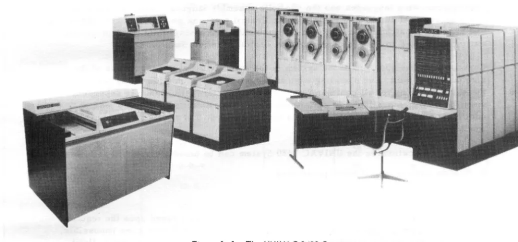
1-l. The UNIVAC 9480 System
1-2. UNIVAC 9480 System Central Processor Unit and Console Configuration
1-3. UNIVAC 9480 System Basic Configuration (Disc Subsystem)
1-4. Typi cal UNIVAC 9480 System Configu ration (Di sc Subsystem wi th Tape)
1-5. Typical UNIVAC 9480 System Configuration (Disc Subsystem with Tape and Data Communi cations Subsystem)
2-l. Basic Instruction Formats (Object Code Form)
2-2. UN IV AC 9480 System Consol e
2-3. UNIVAC 9480 Series Data Communications Subsystem
TABLES
70
70 71 72 72 73
73
74
75
78
85
6
7
8
9
26
28
38
2-1. Symbols Used to Describe Operand Formats 27
2-2. Console Printer Controls and Indicators 29
2-3. Line Terminal Characteristics 36
2-4. UNISERVO 12/16 Magnetic Tape Subsystem Characteristics 44
2-5. UNISERVO VI~C Magnetic Tape Subsystem Characteristics 49
B-l. ASCII (American Standard Code for Information Interchange) Character Codes 78
B-2. EBCDIC (Extended Binary Coded Decimal Interchange Code) Character
1. INTRODUCTION
1.1.
UNIVAC 91000 SERIES COMPUTER FAMILY
The UNIVAC 9000 Series is a computer family that embodies many bold, new design concepts in a unified and low-cost line of data processing equipment. The UNIVAC 9200 processor is a small, card-oriented data processing system with a basic internal storage capacity of 8,192 bytes. The 9200 System can be expanded to the higher performance card- or tape-oriented 9300 System. From this, it is easy to make the transition to the still more powerful tape- or disc-oriented UNIVAC 9480 System shown in Figure 1-1, which has a basic storage capacity of 65,536 bytes with a
storage cycle of 600 nanoseco'nds per two bytes.
Equipment expansions to larger systems or different configurations of the same system are compatible within the UNIVAC 9480 System. This highly desira ble hardware compatibility also applies to software in the UNIVAC 9480 System. Programming compatibility within the wide range of data processing capa bility offered by the UNIVAC 9480 System allows maxi-mum freedom for growth and expansion into larger equipment configurations.
The equipment and programming compatibility features of the UNIVAC 9000 Series allow the entire series to be thought of as essentially one large computer system whose size and configuration are adjustable over a wide range of data processing applications. From the user's point of view, this range of choice is the most economical because a system can always be selected to fit the needs of an installation. Costly time lags where the computing system can be ahead or behind the demands of the user are thereby eliminated.
The UNIVAC 9480 System offers speed, reliability, modularity, compactness, and, most significantly, economy to the user requiring random or sequential batch processing, or communications processing.
The operating system for the UNIVAC 9480 System consists of a comprehensive set of programming aids, control programs and utility services. It is modular in design to fulfill a wide range of data processing requirements. The user may write programs in the common higher level programming languages, COBOL and FORTRAN. These higher level programming languages and the symbolic assembly language permit a choice of the language best suited to the application. Control programs provide for both random and sequential batch processing, and communication processing. Data to be processed can be introduced to the system from either central or remote locations.
Conceptually, the approach to the sys tern is the same for all users, regardless of the size of their system. The operating system is designed to provide (as far as possible) the same functions for all configurations; however, system performance is dependent upon the facilities available. In certain instances, the smaller systems may require additional passes over the data to obtain the same output that a more powerful system" would produce in a single pass.
Computer applications in the UNIVAC 9480 System can be broadly classified as follows:
• Random and sequential batch processing
• Communications-oriented processing
SYSTEM ORIENTATION
MAXIMUM INTERNAL STORAGE
ADD (BINARY) INSTRUCTION TIME (TWO 32-BIT WORDS)
DECIMAL MULTIPLY AND DIVIDE INSTRUCTIONS
CARD READER
PRINTER
MAGN ETIC TAPE RATE
NUMBER OF SELECTOR CHANNELS
SELECTO REGISTERS
DISC STORAGE
Tape/disc
262,144 bytes
6 microseconds
Standa rd
600 cpm or 1000 cpm
900 to 1100 Ipm, 1200 to 1600 Ipm, or 840, 1000, 2000 Ipm
34,160 bytes per second to 192,000 bytes per second
1 standard 1 optional
1.2. GROWTH AND COMPATIBILITY
The UNIVAC 9480 System hardware and software features are at the disposal of the user to any extent he wishes. A basic system can be supplemented by many optional features to meet a wide variety of system needs.
The modular design of the UNIVAC 9480 System, coupled with its high-speed main storage and I/O architecture, provides a dependable base for future extensions. Changes in bus iness demands, applications, programmin g techniques, system configuration, or new input/output devices can be readily incorporated in the UNIVAC 9480 System. This architecture extends the usefulness of the initial planning, programming, and operational procedures used with the system.
The UNIVAC 9480 System is complemented by a wide variety of disc storage, magnetic tape, communications, punched ca rd readin g and punchin g, and high speed printin g devices. Peripheral devices are available with different speeds, capacities, and
industry data compatibility to permit each user to select the most profitable combination for his application.
The multiplexer channel enables many input/output devices to concurrently transfer data to and from the central processor at a rate of 85,000 bytes per second. Two selector channels are available with the system to provide a combined data exchange capability of 666,000 bytes per second.
1.3. SOFTWARE FEATURES
The principal objective of the UNIVAC 9480 System is to make the full power of the processor system available to the user to solve his processing tasks. Implicit in this objective is the need that the software system be consistent with the capabilities of a small- to medium-scale computing system. To meet this objective, UNIVAC 9400 software is used for this member of the UNIVAC 9000 Series, and software documen-tation will be given in the UNIVAC 9400 System Programmer Reference manuals.
The Supervisor is a part of the operating system that operates with problem programs to provide the control necessary for optimum utilization of the UNIVAC 9480 System hardware and software. By use of the Supervisor, the hardware and software systems are effectively coordinated to satisfy the requirements of a growing number of diversi-fied applications. Problems are handled directly and promptly with as little internal bookkeeping as possible without compromising the integrity of the computing system.
1. 3.1. Modularity
Functional modularity has been employed in the design of the Supervisor to ensure its adaptation to a wide range of data processing applications. The user can tailor the Supervisor to his particular applications by parameter selection and specification of the various functional modules at systems generation time.
1.3.2. Multiprogramming
Utilization of central processor unit time is maximized by multiprogramming. A Super-visor can be generated to control from one to five problem programs. In this environ-ment, problem programs are processed concurrently in the processing system. In addition to problem programs, many of the Supervisor functions are designed as autonomous activities capable of being processed as independent programs.
The mul tiprogra mm ing techn iq ue employed by the Supervisor involves the dis tribu tion of processing time to independent programs based on program priorities, time allo-cations, and input/output equipment utilization. Consideration of these factors by the Supervisor assures the user that the distribution of processing time is efficient and equitable.
1.4. COMMUNICATIONS
The UNIVAC 9480 System can be used for communications-oriented data processing through the use of a UNIVAC Data Communications Subsystem (DCS) and the commu-nications adapter. Each com mucommu-nications subsystem is attached to the UNIVAC 9480 System central processor unit by means of one of the eight subchannels provided in the standard multiplexer channel. The communication configurations provide for any number of simplex line positions up to a maximum of 64 input an'd 64 output lines. In the half or full duplex mode a total of 64 lines can be accommodated.
The accuracy of transmission can be controlled through an optional parity check on all transm itted data. Either odd or even parity check can be performed for each character in a message to the central processor unit. Similarly, odd or even parity can be generated for each character transmitted. In addition, a longitudinal
redundancy check may be performed for each input message and generated for each output message.
The Data Communication Subsystem is compatible with Data-Phone* Service, TWX Networks, Telex**, and Wideband.
1.5. EQUIPMENT CONFIGURATIONS
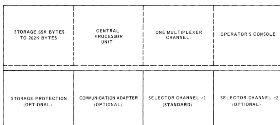
The following diagrams (Figures 1-2 to 1-5) illustrate some of the system config-urations that are available on the ,UNIVAC 9480 System. Figure 1-2 shows the UNIVAC 9480 System central processor unit and console configuration.
I I
I
I
II
I
I
I
I
CENTRALI
I
STORAGE 65K BYTES I
I
ONE MULTIPLEXERI
OPE RATOR'S CONSOLE TO 262K BYTES I PROCESSOR CHANNELI UNIT I I
I
I
II I I
I
I I
I---~ _________ -1- _ _ _ _ _ _ _ _ _
J.- __________
STORAGE PROTECTION COMMUNICATION ADAPTER SELECTOR CHANNEL d SELECTOR CHANNEL ::2 (OPTIONAL) (OPTIONAL) (STANDARD) (OPTIONAl)
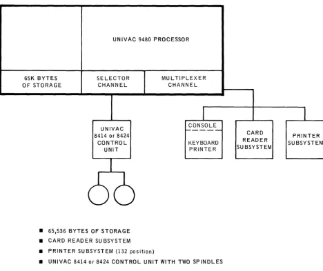
The system configuration shown in Figure
1-3
provides a convenient transition from smaller disc-pack oriented systems. This system, as a result of the auxiliary disc storage, is suited for both scientific and business data pr?cessing. A few of the many applications possible with this system follow:• Billing and accounts receivable • Quality control
• Savings and loan • Personnel analysis
• Statistical analysis • Engineering design
• Payroll and labor distribution • In ven tory control
• Production control
Small files can be more efficiently referenced and maintained with the disc storage. Program libraries, as well as frequently used files, can always be available on disc and the system can be used for short irregularly scheduled runs concurrently with other processing.
UNIVAC 9480 PROCESSOR
65K BYTES SELECTOR MUL TIPLEXER
OF STORAGE CHANNEL CHANNEL
I
I
UNIVAC
---
CONSOLECARD
8414 or 8424 PRINTER
CONTROL KEYBOARD READER SUBSYSTEM
UNIT PRINTER SU BSYSTEM
66
• 65,536 BYTES OF STORAGE • CARD READER SUBSYSTEM
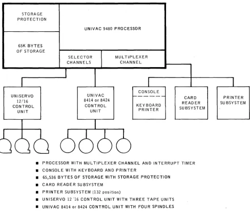
The system configuration shown in Figure 1-4 combines the advantages of the tape and the disc subsystems. A few of the many applications possible with this system follow:
• Billing and accounts receivable • Sales statistics
• Insurance • Production control
• Pension • Engineering des ign
• Order entry • Inventory control
• Personnel statistics
The broad flexibility of disc-stored program libraries and control stream technique provide software and system organization that has been previously available only in the largest computer systems. The tape and disc combinations are well suited for applications where there are large master files having a high percentage of updates each cycle. Also, the use of tapes saves disc-pack cost and provides a fast method of sequential processin g. The discs provide program overlays, ta ble s tora ge, small file storage, and the flexibility of the disc-oriented operating system.
STORAGE PROTECTION
65K BYTES OF STORAGE
UNISERVO 12/16 CONTROL
UNIT
UNIVAC 9480 PROCESSOR
SELECTOR CHANNELS
UNIVAC 8414 or 8424
CONTROL UNIT
MU L TIP LEX E R CHANNEL
CONSOLE
KEYBOARD PRINTER
CARD READER SU BSYSTEM
• PROCESSOR WITH MULTIPLEXER CHANNEL AND INTERRUPT TIMER • CONSOLE WITH KEYBOARD AND PRINTER
• 65,536 BYTES OF STORAGE WITH STORAGE PROTECTION • CARD READER SUBSYSTEM
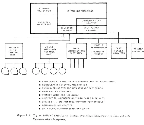
The system configuration shown in Figure 1-5 provides communication capability in addition to the capabilities of the disc and tape system illustrated in Figure 1-4. A few of the many applications provided by addin g the communications facility follow:
• Inquiry systems
• Remote transaction processing
• Data collection from remote terminals
The multiprogramming capabilities of the system permit the communication applications to operate concurrently with batch programs initiated at the system site.
UNISERVO 12 '16 CONTROL
UNIT
STORAG E PROTECTION
65K BYTES OF STORAGE
UNIVAC 8414 or 8424
CONTROL UNIT
UNIVAC 9480 PROCESSOR
SE LECTO R CHANNELS
COMMUN ICATIONS ADAPTER
MUL TIPLEXER CHANNEL
CONSOLE
DATA COMMUNICATIONS
SU BSYSTEM KEYBOARD PRIN TE R
CARD READER SUBSYSTEM
• PROCESSOR WITH MULTIPLEXER CHANN EL AND INTERRUPT TIMER
• CONSOLE WITH KEYBOARD AND PRINTER
• 65,536 BYTES OF STORAGE WITH STORAGE PROTECTION
• CARD READER SUBSYSTEM
• PRINTER SUBSYSTEM (132 position)
• UNISERVO 12 '16 CONTROL UNIT WITH THREE TAPE UNITS
• UNIVAC 8414 or 8424 CONTROL UNIT WITH FOUR SPINDLES
• COMMUNICATIONS ADAPTER
• DATA COMMUNICATIONS SUBSYSTEM (OCS-4)
Figure 7 -5. Typical UNIVAC 9480 System Configuration (Disc Subsystem with Tape and Data Communications Subsystem)
2. SYSTEM
HARDWARE
2.1. The UNIVAC 9480 SYSTEM
The UNIVAC 9480 System is designed as a medium cost, high-performance, system with data processing and communication capability that is well within the reach of the majority of data processing users, and in which no compromise is made with opera tin g potential. In the case of the processor s to rage and circuitry, the resulting high speed permits the UNIVAC 9480 System to compete favorably in the performance of any conventional data processing program.
2.2. CENTRAL PROCESSOR UNIT
Main storage, control, arithmetic, and input/output sections comprise the major parts of the central processor unit. These parts are described in the following paragraphs.
2.2.1. Main Stora ge Characteris tics
2.2.Ll. Addressing and Data Formats
Each eight-bit byte of main storage can be accessed by the problem program. These bytes are addressed consecutively from 0 through 262,143. Bytes may be accessed separately or in groups. The address of a group of bytes is addressed by the leftmost byte of the group. The bits in a byte are also num bered from left to right starting with zero.
Byte Ib 1b Ib§
IbF~
lbI
o
7Ha lfw ord forma ts cons is t of two consecutive bytes.
Halfword
o
7 8 15Fullword formats consist of four consecutive bytes.
Fullword
o
7 8 1516 2324 31Variable data formats consist of a variable number of consecutive bytes.
Variable Data
Format
o
7First Byte
o
7Las t Byte
Fixed-length fie Ids, such as halfwords and full words, ha ve inte gral bo undaries. Fixed-length fields must be loaded in to ma in storage so that the address is evenly divisible by the field length (in bytes). Thus, a halfword must have an address tha t is a multiple of two and a fullword must ha ve an add ress . that is a m ul tiple of four.
2.2.1.2. Low-Order Storage
The low-order 512 bytes of main storage have been reserved to contain specific operating information. The data stored in these locations is accessed by the hard-ware and the operating system during the execution of the appropriate functions. The operating system provides for loading and protecting the appropriate data in these locations.
2.2.1.3. Storage Protection
Program protection in a multiprogrammed environment is achieved by the storage protection feature. The storage protection feature is controlled through the use of the Limits register, which limits the area that anyone program can access for storage of data. The limits register is under control of the Supervisor which loads the address limits of the particular program in operation. An interrupt is generated whenever a write order attempts to address a location outside the bounds of the limits register.
2.2.2. Control Section
The control section controls the sequence in which instructions are executed, and it interprets and controls the execution of each individual instruction, The cycling of main storage is initiated by this section, All of the hardware aspects of interrupt handling, error checking, and protection are performed by the control section, The control section also maintains the instruction address counter and provides for the different processor modes of operation.
The centra 1 processor can reference two sets of 16 genera 1 purpos e re gis ters. Both sets are con tained in lowoorder stora ge. One set is used by the Supervisor and the other set is used by problem programs. This design greatly reduces the interrupt processing time overhead required when only a single set of general registers is used. Thus, when the processing mode is changed between problem program and Supervisor modes, the following steps required in single register systems are unnecessary.
(1) Store the con ten ts of problem program re gis ters.
(2) Load the executive routine data into the registers.
(3) Store the executive routine data.
(4) Reload the problem data back into the registers.
2.2.3. A ri thm etic Section
The arithmetic section performs all data manipulations including binary and decimal arithmetic, and logical operations such as data comparisons, shifting, and single or double indexing of operand addresses. The adder in this section performs arithmetic in twos complement form.
2.2.3.1. Binary (Fixed-Point) Arithmetic
A binary arithmetic operand can be either a 32-bit word or a 16-bit halfword. When possible, 16-bit operands should be specified to conserve storage. The sign of a binary operand is always the leftmost bit of the operand. The following figures illustrate the formats of halfword and fullword fixedcbinary values.
H a If word I ntege r
Fu Ilword
Integer
When a halfword binary number is called from storage, it is always expanded to a right-justified fullword; the sign is extended to the left.
2.2.3.2. Decimal Arithmetic
Decimal number fields can be variable in length and can exist in two formats: unpacked decimal numbers and packed decimal numbers. Decimal operations including add, subtract, multiply, and divide, can be performed only on packed dec ima 1 numbers. Instructions are provided for con verting decimal numbers from unpac ked to pac ked and from packed to unpac ked forma t.
In the un pac ked dec ima 1 format, each byte contains one digit of a mu ltidigit n urn ber. The byte is divided into two equal fields, a zone field and a digit field. A zone value is represented in the most significant four bits; the digit is represented in the least significant four bits. The zone portion of the least significant byte speciQ fies the sign of the number. The unpacked format must be used when data is to be processed by certain
I/O
devices such as the printer. The follow ing figure illustrates the forma t of a three-digit operand.I I
I I
ZONE: DIGIT ZONE: DIGIT
0 7 8 15
Byte Byte
I
I
SIGN I 16
Byte DIGIT
23
In packed format, each byte contains two digits. The least significant four bits of the least significant byte provides the sign of the number. Packed decimal format is used for all decimal arithmetic operations. The following figure illustrates the format of a four-digit number.
I I
ZERO
I
DIGIT DIGITi DIGITi i
0 7 8 15
Byte Byte
T
I DIGIT: 16
Byte SIGN
23
Packed Decimal Oper and
Decimal numbers (0 through 9) are represented in the four-bit binary coded decimal form (0000 through 1001). The codes 1010 through 1111 are used for sign codes. The binary values 1011 and 1101 represent a minus sign and the binary values 1010,1100, 1110 and 1111 represent a plus sign. This assignment of sign codes perm its the use of either of two conventions: American National Standard Code for Information Interchange (ASCII) expanded to eight bits or Extended Binary Coded Decimal Interchange Code (EBCDIC). The codes 1010 (plus) and 1011 (minus) are used in ASCII; the codes 1100 (plus) and 1101. (minus) are used in EBCDIC. A control bit in the Program Status Word determines whether the system is to operate in the ASCII or the EBCDIC mode.
2.2.3.3. Logical Operation's
Logical operations such as comparing, translating, editing, bit setting, and bit testing are performed by the arithmetic section. Logical operations can be per-formed on fixed-length operands and variable-length operands. Logical operations on fixed-len gth operands are performed in the registers; logical opera tions on varia ble-Iength operands are performed in rna in stora ge. The ins truction forma t determines whether the logical operation is to be performed in main storage or in a regis ter.
2.2.4. Input/Output Section
The input/output (I/O) section of the UNIVAC 9480 System central processor unit initiates, directs, and monitors the transfer of data between storage and the peripheral subsystems. After an I/O instruction has been transferred to the control unit from the control section, the data transfer is performed concurrently with other central processor functions.
The I/O section consists of the input/output channels and the standard UNIVAC 9000 Series I/O Interface which connects channels with the unit controllers. This interface is identical for all the I/O control units; it has been designed for use with all of the available peripheral devices, as well as for future devices.
Two selector channels are available in the UNIVAC 9480 System in addition to the multiplexer channel.
2.2.4,1. Multiplexer Channel
control unit occupies one physical connection and uses one shared subchannel address. Each DCS occupies one physical connection but uses up to 32 nonshared subchannel addresses. The console is connected in such a manner that it uses shared subchannel address but it does not use a physical connection. Therefore, the multiplexer channel can accommodate any combination of Data Communication Subsystem(s) and up to seven standard control units by means of the eight physical connections.
Examples of low-speed devices are printers, card readers, card punches, UNISERVO VI-C Magnetic Tape Units, remote communication devices, I/O subsystems such as the UNIV AC 1004 or 1005 Subsystem, and the UNIVAC 9200 or 9300 Subsystem.
Two selector channels are available: one is included in the basic processor; the second is a vaila ble at the option of the us ere
High-speed devices, such as UNISERVO 12 and UNISERVO 16 Magnetic Tape Units and UNIVAC 8414 or 8424 Disc Drive Units may only be connected to the selector channels by way of eight standard control units. Up to 16 I/O devices can be attached to each of the eight control units depending on the particular subsystem selected.
2.2.5. Interrupt Processing Control
The UNIVAC 9480 System contains a very efficient interrupt sy stem tha t makes it a highly capable communications system. The UNIVAC 9480 Interrupt Sys tern provides the means by which the central processor unit changes from the pro blem program state to pri vileged or supervisor state. The seven types of in terrupt employed in the UNIVAC 9480 System are listed below in order of priority:
• Supervisor Call Interrupt - This interrupt results from the execution of a super-visor call ins truction. Sta tus information provides the opera tin g sys tern with a link to parameter information in the calling program .
• Program Interrupt - This interrupt occurs when one of the following exceptions is recognized by the central processor unit.
Illegal operation
Privileged operation a privileged instruction is encountered while the processor is in the problem state
Write Protection - attempting to write data in main storage that is outside the bounds specified by the limits register
Addressing Exception - reference to low-order storage while in the problem state.
• Timer Interrupt - This interrupt is caused when the millisecond timer storage is decremented to zero.
• Selector Channell Interrupt - This interrupt occurs when an interrupt condition has been generated on Selector Channell by a device.
• Selector Channel 2 Interrupt - This interrupt occurs when an interrupt condition has been generated on Selector Channel 2 by a device.
• Shared Multiplexer Channel Interrupt - This interrupt occurs when an interrupt condition has been generated on a shared multiplexer channel. The status is stored in the appropriate Subchanne I Control Word.
• N onshared Multiplexer Channel Interrupt - This interrupt occurs when an interrupt condition has been generated on a nonshared multiplexer channel. The status is tabled which indicates the source and cause of the interrupt.
2.3,. UNIVAC 9480 SYSTEM INSTRUCTION REPERTOIRE
The power and flexibility of the UNIVAC 9480 System is reflected in the instruction repertoire and execution times. The full repertoire includes 70 ins tructions 1 many of which offer several optional variations. The instruction set is supplemented by an input/output device instruction which controls each of the possible peripheral devices.
The UNIVAC 9480 Sys tern ins tructions fall into two functional categories:
• Supervisor
• Standard
2.3.1. Supervisor Instruction Set
The Supervisor (privileged) instruction set is used primarily by the software operating system when operating in the supervisory state. In this state, all instructions
(Supervisor and standard) are valid and can be executed. The privileged general registers are selected and low-order storage can be addressed. Instructions in the Supervisor set cannot be execute? in a problem program.
2.3.2. Standard Instruction Set
The standard (nonprivileged) instruction set is used to write programs for operation in the problem sta te (applica tion and data processin g programs). In this s ta te, the Supervisor (privileged) instructions are invalid, the problem set of general registers is selected, and low-order storage cannot be addressed.
2.3.3. Instruction Types
Instructions can be either 2, 4, or 6 bytes in length. In a two-byte (halfword) instruc-tion, only registers are referenced. A four-byte (two halfword) instruction references main storage once. A six-byte (three ha lfwo rd) instruction references main s tora ge twice., All instructions must be located in storage on halfword boundaries, that is, have an even address" The six instruction types are:
• RR
=
a register to register operation• RX = a register and indexed storage operation
• RS
=
a register and storage operation• SI
=
a storage and immediate operand operation• SSl
=
a storage to storage operation (256-byte maximum length)• SS2
=
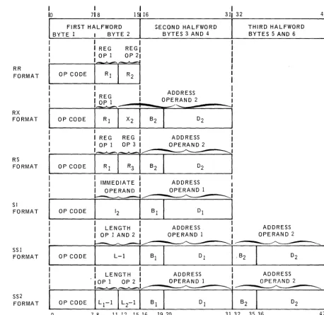
a storage to s tora ge opera tion (16 -byte max imum length)The instruction formats for each type are shown and described in the following sections and are also summarized in Figure 2-1 and in 2.3.3.7.
2.3.3.1. Register to Regis ter Ins tructions (RR)
The RR instructions are two bytes in length and are used primarily to process da ta between regis ters. The maximum data operand tha t can be handled is a full-word of 32 bits; the fullfull-word mayor may not be a signed binary number.
In this format, there are 14 instructions: RR Ins tructions
Add
AND
Branch and Link
Branch on Condition
Branch on Count
Compare
Compare Logical
Exclusive OR
Load
Load and Test
OR
Set Program Mask
Su btract
Supervisor Call
Mnemonic OP Codes
AR
NR
BALRBCR
BCTR
CR
CLR
XR
LR
LTR
OR
SPM
SR
The source code forma ts of the RR ins tructions are:
OP
Rl
OP R 1, R2
OP I
OP M1, R2
where:
• OP is the mnemonic operation code.
is an expression representing a register as operand 1. is an expression representing a register as operand 2.
is actual data expressed in bits to be used for control purposes.
is a four bit da ta rna sk used in tes ting.
The object codes formed by these codes are:
OP CODE
OP CODE Ml R2
2.3.3.2. Register to Indexed Storage Instructions (RX)
The RX instructions are four bytes in length and are used primarily to process data between registers and indexed storage. The maximum data operand that can be handled is a fullword of 32 bits; the fullword mayor may not be a signed binary number.
In this format, there are 20 instructions: RX Instructions
Add
Add Halfword
AND
Branch and Link
Branch on Condition
Branch on Count
Compare
Compare Halfword
Compare Logical
Exclusive OR
Insert Character
Load
Load Address
Load Halfword
OR
Store
Store Character
Store Ha l£word
Su btract
Subtract Ha lfword
Mnemonic OP Codes
A
AH
N
BAL
BC
BCT
C
CH
CL
x
IC
L
LA
LH
o
ST
STC
STH
S
SH
The source code formats of the RX instructions are:
OP R 1 , D2(X2 , B 2)
where:
•
OP
•
Rl•
Ml•
D2
•
X2
•
B2
is the mnemonic operation code.
is an expression representing a register as operand
1.
is a four bit data mask used in testing.
is an expression designating the displacement value of operand 2.
is an expression designating a register whose contents are used to index the displacement and base address of operand 2.
is an expression designating a register whose contents are added to the displacement value to form the effective address of operand 2.
The object codes formed by these source codes are:
OP CO DE Rl X2 B2 D2
0 7 8 11 12 15 16 19 20 31
OP CODE Ml X2 B2 D2
0 7 8 11 12 15 16 19 20 31
The effective address of operand 2 is formed by adding the contents of the base register 82 to the displacement value 02; this mayor may not be modified by add ing the contents of index register X2 .
2.3.3.3. Regis ter to Stora ge Ins tructions (RS)
The RS instructions are four bytes in length and are used to perform multiple register storage and shift operations.
In this forma t, there are seven instructions:
RS Instructions Mnemonic OP Codes
Load Limi ts Register (privileged instruction) LLR
Load Multiple LM
Shift Left Single Logical SLL
Shift Right Single Logical SRL
Store Multiple STM
The source code formats of the RS instructions are:
where:
• OP
OP R 1, D2(B2)
OP R 1, R3 , D2(B 2)
is the mnemonic operation code.
is an expression representing a register as operand 1, or a register which is the first register of a multiregister group.
is an expression representing a register which is the last register of a multiregister group.
is an expression designating the displacement value of operand 2.
is an expression designating a register whose contents is added to the displacement value to form the effective address of operand 2.
The object codes formed by these source codes are:
31
OP CODE Rl R3 8 2 D2
0 7 8 11 12 15 16 19 20 31
OP CODE :
io
7 . 16 19 20 312.3.3.4. Storage and Immedia te Operand Instructions (SI)
The SI instructions are four bytes in length and are used to provide control data for operation of the processor and peripherals. There are eleven instructions in this format.
SI Ins tructions Mnemonic OP Codes
Add Immediate AI
AND NI
Compare Logical CLI
Exclusive OR XI
Halt and Proceed (privileged instruction) HPR
Load Program State Word (privileged instruction) LPSW
Move Immediate MVI
OR 01
Set System Mask (privileged instruction) SSM
Start I/O (privileged instruction) SIO
Test Under Mask TM
The source code formats of the SI instructions are:
OP D1 (B1)
OP D1(8 1),12
where:
• OP is the mnemonic operation code.
• D1 is an expression designating the displacement value of operand
1.
• 81 is an expression designating a register whose contents is added to the displacement value to form the effecti ve address of operand 1.
The object codes formed by these source codes are:
31
loOP CODE
1
The effective address of operand 1 is formed by adding the contents of the base register (B1) to the displacement value (D
1).
2.3.3.5. Storage to Storage Instructions (SSl)
The SS 1 instructions are six bytes in length and are used to process data in storage where the operands are equal in length. The maximum operand may be 256 bytes in length.
In th is forma t, there are nine instructions:
SS 1 Ins tructions Mnemonic OP Codes
AND NC
Compare Logical CLC
Edit ED
Exclusive OR XC
Move Characters MVC
Move Numerics MVN
Move Zones MVZ
OR OC
Translate TR
where:
•
OP•
D1•
L•
Bl•
D2is the mnemonic operation code.
is an expression designating the displacement value of operand 1.
is a value which states the length of both operand 1 and operand 2.
is an expression designating a register whose contents is added to the displacement D1 to form the effective address of operand 1.
is an expression designating the displacement value of operand 2.
•
B2 is an expression designating a register whose contents is added to the displacement D2 to form the effective address of operand 2.The object code formed by this source code is:
OPCODE L-1 B1 D1 B2 D2
0 7 8 15 16 19 20 31 32 35 36 47
The effective address of operand 1 is formed by adding the contents of base register Bl to the displacement value D1 and the effective address of operand 2 is formed by adding the contents of base register B2 to the displacement value D2 .
2.3.3.6. Storage to Storage Instructions (SS2)
The SS2 instructions are six bytes in length and are used to process data in storage where the operands are unequal in length. The maximum operand can be 16 bytes in length.
In this format, there are nine instructions:
SS2 Instructions Mnemonic OP Codes
Add Decimal AP
Compare Decimal CP
Divide Decimal DP
Move with Offset MVO
Multiply Decimal MP
Pack PACK
Subtract Decimal SP
Unpack UNPK
The source code format for these instructions is:
where:
•
OP
is the mnemonic operation code.•
Dl is an expression designating the displacement value of operand1.
• Ll is a va lue designa ting the length of operand 1.
•
B1 is an expression designating a register whose contents is added to the displacement Dl to form the effective address of operand 1.•
D2 is an expression designating the displacement value of operand 2.•
L2 is a value designatin.g the length of operand 2.•
B2 is an expression designating a register whose contents are added to the displacement D2 to form the effective address of operand 2.The object code formed by this source code is:
OP CODE L1-l L2-1 B1 01 B2 O2
0 7 8 11 12 15 16 19 20 31 32 35 36 47
The effective address of operand 1 is formed by adding the contents of base register B1 to the displacement value Dl and the effective address of operand 2 is formed by adding the contents of base register B2 to the displacement value D2 ·
2.3.3.7. Instruction Formats
The basic instruction formats are illustrated in Figure 2-1 and an explanation of the symbols used is provided in Table 2-1. The subscripts 1, 2, and 3 indicate that the given field refers to operand 1, operand 2, or operand 3 respectively. In general, data are processed from operand 2 to operand 1, with the result often replacing the original contents of operand
1.
Operand 3 is a special notation explained in the RS type instruction in 2.3.3.3.Most instructions are two halfwords in length; however, the RR instructions require only one halfword and therefore are executed faster. The SSl and SS2 instructions use three halfwords and require more execution time, which is dependent upon the length of the data processed by the instruction.
RR FORMAT RX FORMAT RS FORMAT SI FORMAT SSI FORMAT SS2 FORMAT I 718 FIRST HALFWORD BYTE 1 I BYTE 2
SECOND HALFWORD BYTES 3 AND 4
o
I
I REG REGI
I OP 1 OP 21
OPCODE
i71~
OP CODE
OP CODE
OP CODE I
I REG
I OP 1
I
I REG REG
I I I
I OP 1 OP 3 1
I
I
IMMEDIATE 1 OPERAND 11
ADDRESS OPERAND 2
--'''-..
ADDRESS OPERAND 2
ADDRESS OPERAND 1
I
LENGTH ADDRESSI
OP 1 AND 2 I OPERAND 1 ~OP CODE
I
L-lI
Bl OJI
I
LENGTH. I
IOPI OP2
OP CODE
7 8 11 12 15 16
ADDRESS OPERAND 1
19 20
I
311 32
l
THIRD HALFWORD BYTES 5 AND 6
ADDRESS OPERAND 2
I
ADDRESS 1
l~:
31 32 35 36 47
The entries in Table
2-1
explain the meaning of the symbols used in describing the instruction formats in Figure2-1.
SYMBOL
OP CODE
L
Ll
L2 Bl
B2
Dl D2
OPI
OP2
OP3
MEANING
Instruction operation code.
The number of the register addressed as operand 1, or a register which is the first register of a multi-register group.
The number of the register addressed as operand 2.
An expression representing a register which is the last register in a multiregister group.
The number of the register to be used as an index for operand 2 of an RX instruction.
The immediate data or device address used as operand 2 of a SI instruction.
The length of operands 1 and 2 as stated in source code.
The length of operand 1 as s ta ted in source code.
The len gth of operand 2 as s ta ted in sou rce code.
The base register for operand 1.
The base register for operand 2.
The displacement for operand 1. The displacement for operand 2.
Operand 1
Operand 2
Operand 3
2.4. CONSOLE
The UNIVAC 9480 System console provides a means of communication between the
operator and operating system. The console consists of a keyboard, printer, switches,
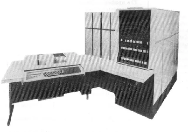
and indicators, which are housed in a platform attached to the processor as shown in Figure 2-2. The associated control and interface I/O logic is housed in the processor. The console is addressed through shared multiplexer subchannel O.
Figure 2-2. UNIVAC 9480 System Console
2.4.1. Keyboard Assembly and Control
The keyboard resembles a standard typewriter keyboard. This assembly consists of
46 keys and a core logic encoding network. Pressing one of the keys causes an
EBCDIC code character and a sprocket pulse to be transmitted in'-bit parallel from the encoding network to the keyboard control logic interface.
The keyboard assembly and control is activated by a read command from the UNIVAC 9480 System central processor unit. This command is requested by pressing the ATTENTION switch located next to the printer, and it remains active throughout
the input operation. During the input operation the printing of each character
signi-fies that the particular character has been sto~ed. The input operation can be
term inated at any point by pressing the ET key. If an incorrect character is typed, pressing the DELETE switch located next to the printer also terminates the input
operation.
2.4.2. Printer Assembly and Control
The UNIVAC 9480 System console printer is an incremental printer capable of
204030
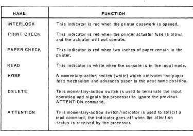
Controls and IndicatorsSeven controls and indicators are located on the console printer. These controls and indicators permit the operator to initiate or terminate a message to the oper-ating system and to control paper movement.
The function of each of these is summarized in Table 2-2.
NAME FUNCTION
INTERLOCK This indicator is red when the printer casework is opened. PRINT CHECK This indicator is red when the printer actuator fuse is blown
and the actuator will not operate.
PAPER CHECK This indicator is red when two inches of paper remain in the pri nter.
READ This indicator is white when the console is in the input mode. HOME A momentarYDaction switch (white) which activates the paper
feed mechanism and advances paper to the next home position. DELETE This momentarYQaction switch is used to terminate the input
operation and signals the processor to ignore the previous ATTENTION command.
ATTENTION This momentarYDaction switch/indicator is used to solicit a read command; the indicator goes off when the attention
status is received by the processor.
Table 2-2. Console Printer Controls and Indicators
2.5, INPUT/OUTPUT DEVICES
A full line of peripheral devices and subsystems is available for use with the UNIVAC 9480 System. These devices and subsystems are:
• UNIVAC 0716 Card Reader Subsystems • UNIV AC 0604 Card Punch Subsystem • UNIV AC 0768 Printer Subsystem • Data Communications Subsystems
• UNIV AC 1004 or 1005 Subsystem
• UNIVAC 0920 Paper Tape Subsystem
• UNISCOPE 100 Display Terminal
• UNIVAC OCT 500 Data Communications Terminal
• UNIVAC OCT 1000 Data Communications Terminal
Descriptions of these devices and subsystems follow.
2.5.1. UNIVAC 0716 Card Reader Subsystem
CARD READING SPEED
INPUT HOPPER CAPACITY
OUTPUT STACKER CAPACITY
READ MODES
OPTIONAL FEATURES
UNIVAC 0716-00
600 cards/ minute
2400 cards
UNIVAC 0716-02
1000 cares/ m i nu te
2 stackers-2000 cards each
Image mode-160 6·bit characters/card Translate mode:
EBCDIC-80 characters/card ASCII-80 characters/card compressed code-80 characters/card
51- or 66-column short card feeds Validity check
Alternate stacker fill Dual translate
The UNIVAC 0716 Card Reader Subsystem includes a self-contained control unit and synchronizer that regulates flow of data and control signals to and from the reader mechanismw This control unit is attached to the UNIVAC 9480 System by m'eans of the multiplexer channeL A separate multiplexer channel physical connec-tion and shared subchannel address are required for the card reader subsystemv
The UNIVAC 0716 Card Reader Subsystem operates at a rate of 600/1000 cards per minute on a column-by-column basis. The read check feature is standard to ensure correct input. Information read from the card is transferred to the processor in
either image mode or translate mode, which includes EBCDIC, ASCII, or compressed code. Image mode and selection of anyone of the translate modes are standard features. The optional dual translate feature permits an additional selection from the two remaining choices offered by the translate mode.
2.5.2. UNIVAC 0604 Card Punch Subsystem
CARD PUNCHING SPEED
INPUT HOPPER CAPACITY
OUTPUT STACKER CAPACITY PUNCH MODES
I/O CHANNELS
OPTIONAL FEATURE
250 cpm
1000 cards
2 stackers - 1000 cards per stacker
Image mode - 160 6-bit characters per
card
Translate mode -80 characters per card
1 shared multiplexer subchannel
Read before punching
The card punch operates at a rate of 250 cards per minute on a row-by-row
basis (12 punching positions per card). Standard features include processing 80-column cards in either punched card code or main storage image code modes. Output cards can be directed to either stacker under control of the program.
The card punch includes a self-contained control unit and a synchronizer which regulates the flow of data and control signals to and from the punch mechanism. This control unit is attached to the UNIVAC 9480 System central processor unit by means of one of the eight physical connections provided in the standard multiplexer channel. A separate shared multiplexer subchannel address is required for each card punch.
I
Data to be punched may be transferred to the output buffer in either of two formats.
In the translate mode, each byte of data is translated by program into the corresponding
card code. In the image mode, data transferred has the two most significant bits
stripped from the byte. The remaining six bits are punched in image code in the
upper or lower half of a card column. The image mode provides the means for punching
up to 160 characters of information into a single 80-column card. A post-punch read
station checks card punching and directs error cards to a selected output stacker.
2.5.3. UNIVAC 0768 Printer Subsystem
The UNIVAC 0768 Printer Subsystem is a freestanding, self-contained unit. The
controlling and synchronizing circuitry, including the 132-character print buffer and
the print mechanisms, are housed within the cabinet. This complete printer subsystem
is connected to the UNIVAC 9480 System by means of the multiplexer channel. A
separate multiplexer channel physical connection and shared subchannel address
are required for each printer subsystem.
A forms container at the base of the unit houses the supply of forms being fed into the
printer. Controls are provided to allow manual adjustment of paper tension, form
thickness, paper alignment, vertical print positioning, horizontal print positioning,
and advancement of forms. The forms-handling mechanism is designed to eliminate
PRINTING SPEED (singl e-I ine spacing)
NUMBER OF CHARACTERS
PRINT POSITIONS PER LINE
HORIZONTAL PRINT SPACING
VERTICAL PRINT SPACING
FORM ADVANCE RATE
FORM WIDTH
FORM LENGTH
NUMBER OF FORM COPIES
FORM ADVANCE
LINE ADVANCE
UNIVAC 0768-00/01 PRINTER SUBSYSTEM
900 Ipm - 63 contiguous characters
11 00 Ipm - 49 contiguous characters
1200 Ipm - 63 contiguous characters
1600 Ipm - 43 contiguous: characters
Maximum of 63 different char-acters consisting of alphabetic characters (A-Z), numeri c characters (0-'9), 27 punctua-tion marks and symbol s
UNIVAC 0768-02/03 PRINTER SUBSYSTEM
840 Ipm -94 contiguous characters 1000 Ipm-87 contiguous characters 2000 Ipm-repeated subset of 14
contiguous characters
Maximum of 94 different characters consisting of alphabetic characters (A-Z and a-z), numeric characters (0-9),32 punctuation marks and symbol s
132 print positions (including spaces) per line
10 print positions per inch
Either 6 or 8 lines per inch as determined by form control tape
33 inches per second at 6 lines per inch spacing 22 inches per second at 8 lines per inch spacing
4 to 22 inches
1 to 22 inches
Up to six-part forms
Loop control
2.5.3.1. UNIVAC 0768-00/01 Printer Su bsystem
The UNIVAC 0768-00/01 Printer Subsystem is a drum printer that prints a maximum of 1100 lines per minute (lpm) depending on the number of characters used. The full character set comprises 63 printable characters on a drum three inches in diameter. If all of the characters to be printed on a line are contained within a 49 contiguous-character subset on the drum and single spacing is specified, printing is at 1100 lpm. If more than 49 contiguous characters are specified and spacing other than single spacing is desired, printing speed decreases accordingly. A speed-up feature (F1071-00) is available, which increases the line printing rate to a maximum of 1600 lines per minute. A 1600 lpm rate is obtained by using a
single-spaced, 43 contiguous-character subset. If more than 43 contiguous charac-ters are specified and spacing other than single spacing is desired, printing speed decreases accordingly.
2.5.3.2. UNIVAC 0768-02/03 Printer Subsystem
The UNIVAC 0768-02/03 Printer Subsystem is a drum printer that prints a maximum of 840, 1000, or 2000 lines per minute depending on the number of characters used. The full character set comprises 94 printable characters (including upper and lower case letters) on a drum five inches in diameter. Printing occurs at 840 lpm when 94 contiguous characters are used. Printing occurs at 1000 lpm when 87 contiguous characters are used. Printing speed increases to 2000 lpm when a numeric set of 14 contiguous characters is used.
2.5.4. Data Communications Subsystem
Communications-oriented data processing is obtained through the use of the UNIVAC 9480 System with from one to four Data Communications Subsystems (DCS) and a communications adapter. Each Data Communications Subsystem (DCS-1, DCS-4, or DCS-16) can accommodate 1, 4, or 16 duplex lines, depending on the type. Each subsystem must be connected to one of the eight physical connections of the multi-plexer channel. Circuitry is included in the DCS to control data transmission between the UNIVAC 9480 System central proces sor unit and the line terminals. The DCS establishes the priority for individual lines when service is requested simultaneously. Also, the DCS signals the operating system when a data transfer between the DCS and the central processor' has been lost.
2.5.4.1. Line Terminal Controller
The line Terminal Controller provides control for the various line terminals and the automatic dialing adapter.
2.5.4.2. Line Terminal
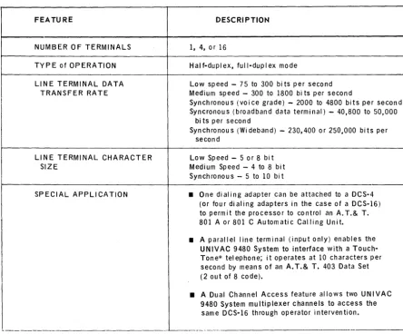
One or more line terminals can be used in half-duplex and full-duplex mode as data handlers either for sending or receiving information to or from the central processor. Several types of line terminals are available to provide low- and medium-speed asyn-chronous operation or to meet synasyn-chronous high-speed requirements. Data characters may range from four to eight bits in size (level) depending on the model and mode of the line terminal. Line terminal characteristics are summarized in Table 2-2.
FEATURE
NUMBER 0 F TERMINALS TYPE of OPERATION LINE TERMINAL DATA
TRANSFER RATE
LINE TERMINAL CHARACTER SIZE
SPECIAL APPLICATION
DESCRIPTION
1, 4, 0 r 16
Half-duplex, full-duplex mode
Low speed - 75 to 300 bi ts per second Medium speed - 300 to 1800 bi ts per second
Synchronous (voice grade) - 2000 to 4800 bits per second Syncronous (broadband data terminal) - 40,800 to 50,000
bits per second
Synchronous (Wideband) - 230,400 or 250,000 bits per second
Low Speed - 5 or 8 bit Medium Speed - 4 to 8 bi t Synchronous - 5 to 10 bi t
• One di al ing adapter can be attached to a DCS-4 (or four dialing adapters in the case of a DCS-16) to permit the processor to control an A. T.& T. 801 A or 801 C Automatic Calling Unit.
• A parallel line terminal (input only) enables the UNIVAC 9480 System to interface with a Touch-Tone* telephone; it operates at 10 characters per second by means of an A.T.& T. 403 Data Set (2 out of 8 code).
• A Dual Channel Access feature allows two UNIVAC 9480 System multiplexer channels to access the
same DCS-16 through operator intervention.
~--- ~----.--.---
_____ --II
2.5.4.3. Communications Interface
The communications interface connects a line terminal with a common carrier line. The available Communication Interfaces meet both the EIA RS 2328
(Industry Standard Interface) and the MIL-STD-188B (Electrical Circuit Compati-bility-Government) specifications. Each input/output line requires one Com-m unication Interface.
2.5.4.4. Asynchronous Timing Assembly
The asynchronous timing assembly provides a clock source for asynchronous line terminals. A single unit provides one baud rate for an entire Data Communications Subsystem. Asynchronous timing assemblies are available in baud rates up to
2400 baud. Each different speed asynchronous line terminal requires an asynchronous timing assembly. The maximum number of ATA's is eight in the case of the DCS-16.
2.5.4.5. Synchronous Timing Assem bly
The synchronous timing assembly provides a clock source for synchronous com-munication. Clock signals are supplied for transmission, and provide the baud rates of 600, 1200, and 1800. These assem blies are needed only in a synchronous mode of operation where an asynchronous modem is used or where there is no external synchronized clock.
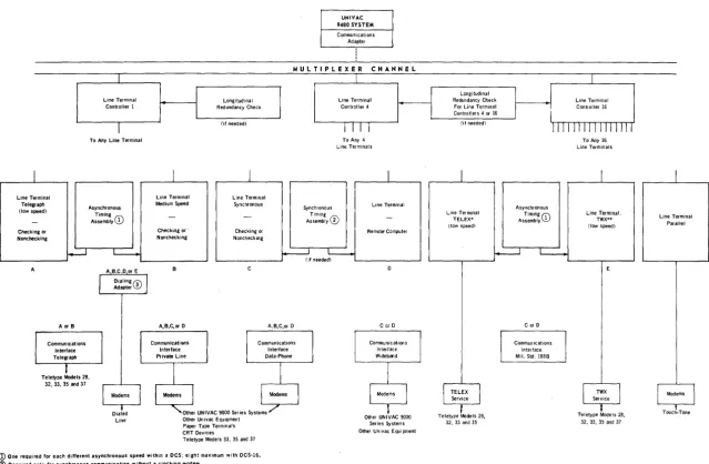
2.5.4.6. Configurations
The Data Communications Subsystem configurations have been classified into the following types:
• DCS-1 provides either one half-dup lex or full-duplex position.
• DCS-4 provides either four half-duplex or full-duplex positions.
• DCS-16 provides either 16 half-duplex or full-duplex positions.
The configuration shown in Figure 2-3 shows a UNIVAC Data Communications Subsystem connected to some of the more commonly used remote devices. It should be noted that each remote device requires a specific combination of the following units:
• Line Terminal Controller
• Line Terminal
• Timing Assembly - Asynchronous Timing Assembly or Synchronous Timing Assembly
• Dialing Adapter
• Communication Interface
w 00
I
Line Terminal Telegraph (low speed) Checking or Nonchecking ---J ILine Terminal Controller 1
I
To Any Line TerminalAsynchronous
A;~::~YCD
I
Line Terminal Medium Speed
Checking or· Nonchecking
I
1
Redundancy Check Longitudinal (if needed)I
Line Terminal Synchronous
Checking or Nonchecking
I
UNIVAC 9480 SYSTEM
Communications Adapter
MULTIPLEXER CHANNEL
I
Line Terminal Controller 4
I I I I To Any 4
Line Terminals
I
Synchronous Line Terminal A;~;~:~y0
Remot .. Computer
~ L
-' - - - -' L -_ _ _ _ _ _ _ ..J (if needed) L -_ _ _ _ _ _ ...J
A
AorB
Teletype Models 28, 32, 33, 35 and 37
Dialed Line
A,B,C,or D
Other UNIVAC 9000 Series Systems Other Univac Equipment Paper Tape Terminals CRT Devices
Teletype Models 33, 35 and 37
Cor D
Other UNIVAC 9000
Series Systems Other Univac Equipment
Longitudinal Redundancy Check
For Line Terminal Controllers 4 or 16
(if needed)
Line Terminal TELEX· (low speed)
Teletype Models 28,
32, 33 and 35
I I
Asynchronous AS:~:i~l~
CD
Cor D
Commun ications Interface Mil. Std. 188B
I
Line Terminal Controller 16
1111111111111111 To Any 16 Line Terminals
Line Terminal. TWX·· (low speed)
Teletype Models 28,
32, 33, 35 and 37
I
Line Terminal Parallel
f Modems
I
t
2.5.5. UNIVAC 1004 or 1005 Subsystem
The UNIVAC 1004 or 1005 Subsystem is a powerful processing unit with arithmetic,
logical, and editing capabilities allied to a modular 961-character core storage.
Standard peripheral units are a 400 cpm or 615 cpm card reader, a line printer
operating at 400 Ipm or 600 Ipm with a 63 character set and 132 character print
line w-idth. A card punch operating at 200 cards per minute may also be included.
Functions of the standard peripheral units (including the card punch) are available
to the UNIVAC 9480 System when this subsystem is in online mode.
Optional units for the offline configuration are a second bank of 961 characters of
core storage, a second card reader (400 cpm), a card punch or card read/punch
(200 cpm), UNIVAC 1001 Card Controller, paper tape reader (400 cps), a paper tape
punch (110 cps), and one or two UNISERVO VI-C Magnetic Tape Units.
A UNIVAC 1004 or 1005 Subsystem can be connected online, by means of one of the
eight physical connections of the basic multiplexer channel and a 1004/1005 channel
adapter, to the UNIVAC 9480 System to provide card reading, card punching, and
printing capability.
A special plugboard is required when the UNIVAC 1004 or 1005 Subsystem is to be
used only with the UNIVAC 9480 System. The UNIVAC 1004 or 1005 Subsystem retains its freestanding processing power when used in this configuration. The
UNIVAC 1004 or 1005 Subsystem can be switched to offline mode at any time
to operate as a standard freestanding system.
By attaching one of several types of line terminals, this subsystem can function as
a remote data processor connected through a communications line to the UNIVAC 9480 System. Transmission at speeds of 2000, 2400 or 40,800 bauds is possible, depending upon the types of line terminals and communications facility employed.
ONLINE AND OFFLINE
CARD READING SPEED 400 or 615 cpm
CARD PUNCHING SPEED 200 cpm
PRINTING SPEED 400 or 600 Ipm
PRINTABLE CHARACTERS 63 plus space
NUMBER OF CHARACTERS PER LINE 132
NUMBER OF LINES PER INCH 6 or 8
MAIN STORAGE 961 character positions
NUMBER OF INPUT/OUTPUT CHANNELS USED 1 OFFLINE ONLY
CARD READING SPEED 400 cpm auxiliary reader or
1000 or 2000 cpm with UNIVAC 1001 Card Controller
MAIN STORAGE 1922 character positions
MAGNETIC TAPE One or two UNISERVO VI-C Tape
Units
MAGNETIC TAPE CODE CONVERSION Available in UNIVAC 1004 Subsystem using the automatic translate feature TAPE TRANS FER RATE 8,500; 23,700; and 34,200 characters
per second
RECORDING DENSITY 200, 556, or 800 ppi
PAPER TAPE READ 400 characters per second
PAPER TAPE PUNCH 110 characters per second
REQUIRED FEATURES
PUNCH STACKER SELECT
*
80-COLUMN READ CAPABILlTY**CODE IMAG