Volume 2006, Article ID 23818, Pages1–15 DOI 10.1155/ASP/2006/23818
Wireless Multicarrier Communications via
Multipulse Gabor Riesz Bases
Manfred M. Hartmann,1, 2Gerald Matz,2and Dieter Schafhuber3
1ARC Seibersdorf Research GmbH, Donau-City-Straße 1, A-1220 Wien, Austria
2Institute of Communications and Radio Frequency Engineering, Vienna University of Technology, Gußhausstraße 25/389,
A-1040 Wien, Austria
3BMW Forschung und Technik GmbH, Hanauer Straße 46, D-80992 M¨unchen, Germany
Received 29 September 2004; Revised 19 January 2005; Accepted 5 April 2005
We introducemultipulse multicarrier(MPMC) modulation, a wireless communication scheme that augments traditional single-pulse multicarrier systems by using multiple single-pulses at the transmitter and the receiver. The mathematical foundation of MPMC systems is established by the novel concept ofmultipulse Gabor Riesz bases. We adaptZak-Fourierdomain tools previously de-veloped formultiwindow Gabor framesto analyze and design(bi)orthogonalmultipulse Gabor Riesz bases and the corresponding MPMC systems in a computationally efficient manner. Furthermore, explicit expressions for the interference power and the spec-tral efficiency in MPMC transmissions over time-varying multipath channels are derived. The superiority of MPMC modulation over single-pulse multicarrier systems is finally demonstrated via numerical simulations.
Copyright © 2006 Hindawi Publishing Corporation. All rights reserved.
1. INTRODUCTION
1.1. Background and contributions
Multicarrier modulation[1–3] is an attractive technique for high data-rate wireless communications. Cyclic prefix or-thogonal frequency-division multiplexing (CP-OFDM) [4–7] is a multicarrier scheme that is being used or proposed for numerous wireless standards like WLAN (IEEE 802.11a/g/n, HIPERLAN/2), broadband wireless access (IEEE 802.16), wireless personal area networks (IEEE 802.15), and digital audio and video broadcasting (DAB, DRM, DVB-T). More-over, it is a promising candidate for mobile radio systems be-yond 3G. Recently,pulse-shapingOFDM [8,9] and biorthog-onal frequency-division multiplexing[9–12] have been shown to be less susceptible to channel distortions than CP-OFDM. We unifyingly refer to all of the above schemes assingle-pulse multicarrier(SPMC) systems.
In this paper, we develop the foundations ofmultipulse multicarrier(MPMC) modulation, a novel wireless commu-nication scheme that extends SPMC systems by using mul-tiple transmit and receive pulses [13]. MPMC modulation is similar in spirit to multiwindow Gabor expansions [14] that extend the Gabor expansion [15, 16] by using mul-tiple windows. It establishes a unifying framework for the various SPMC systems discussed inSection 1.2and features increased design freedom which can be used to optimize sys-tem performance (cf. [17,18]).
The specific contributions of the paper are as follows.
(i) InSection 2, we introduce and discuss MPMC modu-lation and point out its remodu-lation to existing multicarrier schemes. An equivalent MPMC system formulation in terms of the piecewise Zak transform and a 2D Fourier transform is presented inSection 3.
(ii) General linear modulation schemes are studied using the theory of Riesz bases inSection 4. Specializing this to the MPMC context leads us to the novel concept of multipulse Gabor Riesz bases (Section 5).
(iii) We derive explicit expressions for the interference power and the spectral efficiency of MPMC trans-missions over time-varying multipath channels in Section 6.
(iv) Numerical examples regarding the design and perfor-mance of MPMC systems are provided inSection 7, including a comparison with SPMC systems.
Some conclusions are finally provided inSection 8. As a basis for the introduction of MPMC modulation, we next discuss SPMC systems in slightly more detail.
1.2. Single-pulse multicarrier systems
f
F
T t
(a) f
F
T t
(b)
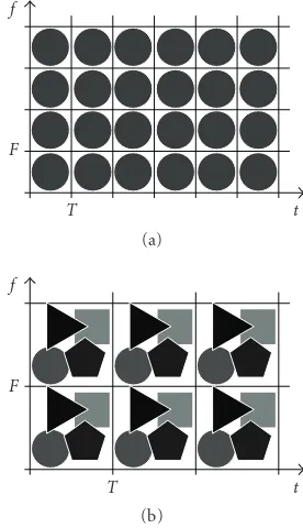
Figure1: Schematic TF domain illustration of (a) an SPMC system and (b) an MPMC system withM=4.
subcarrier index, resp.) to the transmit signal
s(t)= ∞
l=−∞ K−1
k=0
al,k,gl,k(t), gl,k(t)g(t−lT)ej2πkFt. (1)
Here,g(t) is the prototype transmit pulse, andT andF de-note the symbol duration and subcarrier spacing, respec-tively. It is seen that each symbolal,k is carried by a pulse gl,k(t) localized about the time-frequency (TF) lattice point
(lT,kF) (cf.Figure 1(a)).
The SPMC demodulator calculates the receive sequence1
xl,k=
tr(t)γ ∗
l,k(t)dt, γl,k(t)γ(t−lT)ej2πkFt, (2)
wherer(t) andγ(t) denote the received signal and the proto-type receive pulse, respectively.
For the case of an ideal channel (r(t)=s(t)), perfect sym-bol recovery (xl,k=al,k) is obtained if and only if the pulses g(t),γ(t) and the lattice constantsT,Fare designed such that thebiorthogonality conditiontg(t)γl∗,k(t)dt=δlδkis satisfied
(cf.Section 4). For this, it is necessary thatTF ≥ 1 (TF is termed theredundancy). A larger redundancy amounts to a guard regionbetween neighboring pulses which is beneficial for reducing intersymbol and intercarrier interference (ISCI)
1Integrals are from−∞to∞unless stated otherwise. Throughout the pa-per, the superscripts∗,T, andHdenote the complex conjugate, trans-pose, and Hermitian transtrans-pose, respectively.
but reduces the number of symbols transmitted per second and Hertz.
Since wireless communication systems often operate over rapidly time-varying channels, minimizing ISCI is important to assure high spectral efficiencies. For SPMC systems, this problem leads to the development of pulse-shaping OFDM [8,9] and BFDM [9–12]. Lattice OFDM [19] is another at-tempt to reduce ISCI by using a hexagonal TF lattice. Finally, OFDM/offset QAM(OFDM/OQAM) [9,20–22] is an SPMC variant that allows to use critical redundancyTF =1 at the cost of increased equalization complexity.
2. MULTIPULSE MULTICARRIER SYSTEMS
2.1. MPMC modulator and demodulator
The fundamental idea behind MPMC systems is to use multiple transmit and receive prototype pulses [13] (see Figure 1(b)).
The MPMC modulator usesMlinearly independent pro-totype transmit pulses g(m)(t), m = 1,. . .,M. We will
re-fer to the vector g(t) = [g(1)(t)· · ·g(M)(t)]T as transmit
multipulse. At symbol time land subcarrierk,M symbols
a(l,mk),m=1,. . .,M, are transmitted in parallel via the pulses
gl(,mk)(t)=g(m)(t−lT)ej2πkFt,m=1,. . .,M(the symbol
du-rationTand the subcarrier spacingFconstitute the MPMC TF lattice parameters). WithK again denoting the number of subcarriers, the MPMC transmit signal equals
s(t)=
M
m=1
∞
l=−∞ K−1
k=0
al(,mk)gl(,km)(t). (3)
Hence, MPMC modulation can be interpreted as super-position of M SPMC modulators with different transmit pulses. Using the vector notationsal,k=[a(1)l,k · · ·a
(M) l,k ]T, and
gl,k(t) =
gl(1),k(t)· · ·g (M)
l,k (t)]T, the MPMC transmit signal
can be written as (cf. (1))
s(t)=
∞
l=−∞ K−1
k=0
aTl,kgl,k(t). (4)
At the receiver, the MPMC demodulator employs a re-ceive multipulse γ(t) = [γ(1)(t)· · ·γ(M)(t)]T consisting of M linearly independent prototype receive pulses γ(m)(t),
m = 1,. . .,M, to calculate the vector sequence xl,k =
[x(1)l,k · · ·x(l,Mk)]Tfrom the received signalr(t) according to (cf.
(2))
xl,k=
tr(t)γ ∗
l,k(t)dt. (5)
Here,γl,k(t)=[γl(1),k(t)· · ·γ (M)
l,k (t)]Twithγ (m)
l,k (t)=γ(m)(t− lT)ej2πkFt.
Block diagrams of MPMC modulator and demodulator are shown inFigure 2.
2.2. Biorthogonality and TF lattice
For MPMC systems,perfect symbol recovery(xl,k=al,k) in the
al,0
al,1
al,K−1
g(t−lT)
g(t−lT) . . . g(t−lT)
1 × ej2πFt
×
ej2π(K−1)Ft
× +
s(t) r(t) 1 × e−j2πFt
×
e−j2π(K−1)Ft
×
γ∗(−t)
γ∗(−t)
. . .
γ∗(−t)
xl,0
xl,1
xl,K−1 lT
lT
lT
Figure2: Block diagrams of MPMC modulator and demodulator.
if the multipulsesg(t) andγ(t) and the TF lattice parameters
TandFare chosen such that thebiorthogonality condition
tg(t)γ H
l,k(t)dt=δlδkI (6)
is satisfied (i.e.,{gl,k(t)}and{γl,k(t)}arebiorthogonalsets).
If in additiong(t)=γ(t), then{gl,k(t)}is an orthogonal set.
(Bi)orthogonal pulses require that the sets{gl,k(t)},{γl,k(t)}
constitutemultipulse Gabor Riesz bases(seeSection 5) which in turn presuppose that the redundancy TF/M satisfies
TF/M ≥ 1, consistent with the single-pulse case. Thus, in-creasing the number of pulses M requires a corresponding reduction of the TF lattice density (cf.Figure 1).
For fixedM, choosing the TF lattice parametersT and
Fis equivalent to specifiying thelattice ratioT/Fand the re-dundancyTF/M. Choosing the redundancyTF/Mis a trade-offbetween high spectral efficiency (achieved with small re-dundancy) and robustness against ISI/ICI (obtained for large redundancy that reduces the overlap of adjacent pulses). Typ-ically,TF/M=1 +with=0.02· · ·0.5 (according to the Balian-Low-type theorem discussed inSection 5,TF/M=1 leads to poorly localized pulses). Regarding the lattice ratio, symmetry arguments suggest the choiceT/F=τmax/νmax(cf.
[10,19] for the caseM = 1), whereτmax andνmax are the
maximum delay and the maximum Doppler frequency, re-spectively, of the channel. The impact of the MPMC TF lat-tice on spectral efficiency will be illustrated inSection 6.
2.3. Special cases
Various existing SPMC systems fit within the MPMC frame-work as special cases. In particular, (pulse-shaping) OFDM [3–5,8,9] and BFDM [9–12] are simple special cases with
M=1.
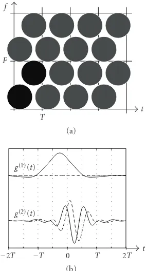
Lattice OFDM[19], an SPMC scheme using an orthog-onalized Gaussian pulseg(t) on a hexagonal TF lattice (see Figure 3(a)), can be viewed as MPMC system with M = 2 and transmit/receive multipulsesg(t) = γ(t) = [g(t)g(t− T/2)ejπFt]T(cf.Figure 3(b)).
OFDM/OQAM [9,20–22] can be interpreted asM =4 MPMC system with real-valued transmit symbols and trans-mit multipulse g(t) = [g(t)jg(t)ejπt/T jg(t −T/2)g(t − T/2)ejπt/T]T (see Figure 4(a)). While OFDM/OQAM uses
f
F
T t
(a)
g(1)(t)
g(2)(t)
−2T −T 0 T 2T t (b)
Figure3: Lattice OFDM system: (a) equivalent MPMC representa-tion withM=2, (b) corresponding MPMC multipulse forTF/M=
1.5 (solid line: real part, dashed line: imaginary part).
TF/M = 1/2, perfect symbol recovery for an ideal channel can still be achieved due to the restriction to real-valued sym-bols.
Finally, multicarrier direct sequence CDMA (MC-DS-CDMA), a combination of OFDM and CDMA [23], can be interpreted as an MPMC system where the prototype pulses
{g(m)(t)},m = 1,. . .,M, correspond to theMCDMA chip
sequences (cf.Figure 4(b)).
3. ZAK-FOURIER FORMULATION
transform. We note that the (piecewise) Zak transform has successfully been applied for the analysis and design of (mul-tiwindow) Gabor frames [15,16]. This description applies to systems with rational lattice,TF =p/q,p,q∈N(note that this is not a severe restriction). For simplicity, we first con-sider the case of integer TF lattice,TF =p ∈Nand discuss the extension to rational TF lattice inSection 3.3.
3.1. (Piecewise) Zak transform and 2D Fourier transform
TheZak transformof a signal2s(t)∈L2(R) is defined as (cf.
[14])
(Zs)(η,θ)√1
F ∞
n=−∞ s
η+n
F
e−j2πθn. (7)
In our context,Fis the MPMC subcarrier spacing. The Zak transform is (quasi-)periodic in the sense that
(Zs)(η+m,θ+n)=ej2πθm(Zs)(η,θ), m,n∈Z. (8)
Consequently, it is uniquely defined by its values on the unit square (η,θ)∈U2,U =[0, 1). The Zak transform can be
inverted via the relation
s
t+n
F
=√1 F
1
0(Zs)(tF,θ)e
j2πθndθ, 0≤t < 1 F, n∈Z,
(9)
and it is a unitary mapping fromL2(R) to the Hilbert space
L2(U2) with inner product
Zs,Zr L2(U2) 1
0
1
0(Zr)
∗(η,θ)(Zs)(η,θ)dη dθ. (10)
The Zak transform is covariant to time and frequency shifts in the sense that
s(t)=s(t−τ)ej2πνt
⇐⇒(Zs)(η,θ)=ej2πην/F(Zs)η−τF,θ− ν F
. (11)
For integer TF lattice, (8) and (11) imply that
sl,k(t)=s(t−lT)ej2πkFt ⇐⇒ Zsl,k
(η,θ)=e−j2π(l pθ−kη)(Zs)(η,θ). (12)
Thepiecewise Zak transform(PZT) ofs(t) is defined as the length-pvector [14]
(Zps)(η,θ)
(Zs)(η,θ) (Zs)
η,θ+ 1
p
· · ·(Zs)
η,θ+ p−1
p T
.
(13)
2The space of functions (sequences) that are square-integrable (square-summable) on a setSare denoted byL2(S) (l2(S)).
0
0
0
0
−T 0 T t
g(1)(t)
g(2)(t)
g(3)(t)
g(4)(t)
(a)
0
0
0
0
−T 0 T t
g(1)(t)
g(2)(t)
g(3)(t)
g(4)(t)
(b)
Figure 4: Multipulses for special cases of MPMC modulation: (a) OFDM/OQAM, (b) MC-DS-CDMA withM =4. (solid line: real part, dashed line: imaginary part).
It is uniquely defined by its values on the rectangle (η,θ)∈
[0, 1)×[0, 1/ p) and it is a unitary mapping fromL2(R) to
the Hilbert spaceHp L2([0, 1)×[0, 1/ p);Cp) with inner
product
Zps,Zpr
Hp
1
0
1/ p
0 (Zpr)
H(η,θ) Z ps
(η,θ)dθ dη.
(14)
Due to their unitarity, Zak transform and PZT preserve the
L2(R) inner products,r
tr∗(t)s(t)dt:
s,r = Zs,Zr L2(U2)=
Zps,Zpr
Hp. (15)
Note that the TF shift covariance properties (11) and (12) also apply to the PZT.
We will further use the following 2DFourier transform (2D-FT) of 2D vector sequencesxl,k:
(Fx)(η,θ)p ∞
l=−∞ ∞
k=−∞
xl,ke−j2π(l pθ−kη). (16)
Like the PZT, (Fx)(η,θ) is uniquely defined by its values on the rectangle (η,θ) ∈ [0, 1)×[0, 1/ p). The 2D-FT is a unitary mapping from the Hilbert space of 2D sequences in
l2(Z2;CM),M ∈N, with inner productx,a l,kaHl,kxl,k
to the Hilbert spaceHM. The inverse2D-FT ofA(η,θ) =
(Fa)(η,θ) is defined as
F−1A l,k
p
1
0
1/ p
0 A(η,θ)e
j2π(l pθ−kη)dθ dη. (17)
3.2. MPMC modulator and demodulator
We next reformulate the MPMC modulator (4) and the MPMC demodulator (5) in terms of PZTs and 2D-FTs.
Using (12) and (16), the PZT of the MPMC transmit sig-nal in (4) can be calculated as
Zps
(η,θ)=
M
m=1
∞
l=−∞ ∞
k=−∞
Zpgl(,mk)
(η,θ)a(l,mk)
= M
m=1
Zpg(m)
(η,θ)
∞
l=−∞ ∞
k=−∞
e−j2π(l pθ−kη)a(l,mk)
=√1p M
m=1
Zpg(m)
(η,θ) Fa(m)(η,θ)
=Mg(η,θ)(Fa)(η,θ),
(18)
where
Mg(η,θ)
1
√p Zpg(1)
(η,θ)· · · Zpg(M)
(η,θ) (19)
denotes thep×Mmodulator matrix. Equation (18) consti-tutes the Zak-Fourier formulation of the MPMC modulator (4) and amounts to a simple matrix-vector multiplication for each (η,θ).
To reformulate the MPMC demodulator (5) in the Zak-Fourier domain, we use the unitarity (15) and the TF shift covariance (cf. (12)) of the PZT,
x(l,mk)=
r,γ(l,mk)
=Zpr,Zpγl(,mk)
Hp
=
1
0
1/ p
0 Zpγ
(m)H(η,θ)(Z
pr)(η,θ)ej2π(l pθ−kη)dθ dη.
(20)
Comparing the last expression with (17), we obtain
Fx(m)(η,θ)
=√1p Zpγ(m)
H
(η,θ) Zpr
(η,θ), m=1,. . .,M,
(21)
which can again be rewritten as a Zak-Fourier domain matrix-vector multiplication,
(Fx)(η,θ)=Dγ(η,θ) Zpr
(η,θ). (22)
Here,Dγ(η,θ) denotes theM×pdemodulator matrixdefined as
Dγ(η,θ)√1p Zpγ(1)
(η,θ) · · · Zpγ(M)
(η,θ)H.
(23)
Note that (19) and (23) imply thatMH
g(η,θ)=Dg(η,θ).
Furthermore, for an ideal channel, that is,r(t) = s(t), we have (Fx)(η,θ) = Dγ(η,θ)Mg(η,θ)(Fa)(η,θ). Block
dia-grams for the Zak-Fourier implementation of MPMC mod-ulator and demodmod-ulator are shown inFigure 5.
al,k Ᏺ Mg(η, θ) ᐆ−p1 s(t) (a)
r(t) ᐆp Dγ(η, θ) Ᏺ−1 xl,k (b)
Figure 5: Zak-Fourier domain implementations of (a) MPMC
modulator, (b) MPMC demodulator.
3.3. Rational TF lattice
The foregoing results for integer TF lattice (TF=p∈N) can straightforwardly be generalized to MPMC systems with ra-tional lattices,TF =p/q,p,q∈N. In particular, an MPMC system withM×1 transmit/receive multipulsesg(t),γ(t) and rational TF latticeTF = p/qcan equivalently be viewed as MPMC system with transmit/receive multipulses
g(t)=gT(t) gT(t−T) · · · gT t−(q−1)TT,
γ(t)=γT(t) γT(t−T) · · · γT t−(q−1)TT,
(24)
of lengthM=qMandintegerTF latticeTF = p,T =qT. The corresponding transmit/receive symbols are
al,k=
aTql,k aTql+1,k · · · aTql+q−1,kT,
xl,k=
xT
ql,k xTql+1,k · · · xTql+q−1,k
T .
(25)
The previously developed Zak-Fourier formulations of MPMC modulator and demodulator can then be applied to the equivalent MPMC system with integer TF lattice. Note, however, that the size of the matrices and vectors involved (and thus computational complexity) increases withq.
4. (BI)ORTHOGONAL MODULATION VIA RIESZ BASES
This section provides a brief introduction to Riesz bases [15,25,26] and discusses their relevance to linear modu-lation formats aiming at perfect symbol recovery for ideal channels. The general discussion of this section will be spe-cialized and deepened for MPMC systems inSection 5. We note that Riesz bases involve similar mathematical tools as frames[15,16,25,26] to which they are closely related.
4.1. Riesz bases
A sequence{gk(t)}k∈K of functions inL2(R) with a
count-able index setK is called aRiesz basisfor its closed linear span3 if and only if there exist two constants A
g,Bg with
0< Ag≤Bg <∞, such that4
Ag
k∈K
ak2 ≤
k∈K
akgk
2 ≤Bg
k∈K
ak2
(26)
for any{ak} ∈ l2(K). The tightest possible boundsA g,Bg
in (26) are calledlower Riesz boundandupper Riesz bound, respectively, and their ratio Bg/Ag is the condition number
of the Riesz basis. IfAg = Bg, then the sequence{gk(t)}is
anorthogonalbasis (orthonormalifAg =Bg = 1). Two sets {gk(t)},{γk(t)}are calledbiorthogonalifgk,γl = δk−lfor
allk,l∈K. If and only if a sequence{gk(t)}is a Riesz basis,
then there exists a (not necessarily unique) biorthogonal se-quence{γk(t)}which is also a Riesz basis. TheGram operator Ggassociated to a Riesz basis{gk(t)}is a bounded,
positive-definite (hence also selfadjoint and invertible) linear operator [27] that mapsl2(K) tol2(K) according to
Gga
k
k∈K
akgk,gk. (27)
For any Riesz basis {gk(t)}, an associated modulation
(synthesis) operator can be defined as the mapping from
l2(K) toL2(R) given by
Mga
(t)
k∈K
akgk(t). (28)
Furthermore, a demodulation (analysis) operator Dγ
map-pingL2(R) tol2(K) can be defined for any Riesz basis{γ k(t)}
as
Dγs
k
s,γk
. (29)
Note that any linear modulation scheme can be cast in the forms (28), (29).
If and only if{gk(t)}and{γk(t)}are biorthogonal Riesz
bases, thenDγis a left inverse ofMg:
DγMg =I⇐⇒
gk,γl
=δk−l (30)
(for an orthogonal Riesz basisDgMg = AgI). In this case,
the coefficients ak in (28) can be reobtained from s(t) =
(Mga)(t) via (29). This corresponds to perfect symbol
recov-ery in a linear modulation scheme with transmit symbolsak,
transmit pulsesgk(t), transmit/receive signals(t), and receive
pulsesγk(t).
Note that the adjoint [27] ofDg is given byDg+ =Mg,
that is,Dgs,a = s,Mga . Furthermore, the Gram
opera-tor can be written asGg=DgMg.
4.2. (Bi)orthogonalization
We next consider a generalized procedure for computing (bi)orthogonal Riesz bases. Starting from a prescribed Riesz
4Here,s =s,s denotes the usualL2(R) norm.
basis{gk(t)}with associated modulation and Gram
opera-torsMg andGg, we define anα-parametrized sequence of
functions{gkα(t)}as (cf. [19])
gkα(t)
MgG−g1/2+αδk
(t) (31)
(here,δk
l =δl−k). Note thatgk1/2 (t)=gk(t).
It can be verified that{gkα(t)}is also a Riesz basis with
associated modulation operatorMgα =MgG−g1/2+α, demod-ulation operator Dgα = G−g1/2+αDg, and Gram operator Ggα = G2gα. The associated Riesz bounds areAgα = A2gα, Bgα = Bg2α for α ≥ 0 andAgα = B2gα,Bgα = A2gα for α≤0. Using (30), it is seen that{gkα(t)}and{g−
α k (t)}are
biorthogonal,
Dg−αMgα =Gg−1/2−αDgMgG−g1/2+α=I. (32)
Hence, {gk0(t)} is an orthonormal Riesz basis (Agα = Bgα = 1). Furthermore,{gk−1/2(t)}is the canonical bior-thogonal basis for the originally prescribed Riesz basis
{gk(t)} = {gk1/2(t)}.
Consider a linear modulation scheme with transmit pulses{gkα(t)}and receive pulses {g−
α
k (t)}derived from
a prescribed Riesz basis{gk(t)}. There are three important
cases.
(i) α=0. Here, both transmitter and receiver use the or-thogonal pulsesgk0(t) = (MgG−g1/2δk)(t). For
trans-mission over additive white Gaussian noise (AWGN) channels, this maximizes the SNR after demodulation (“matched filter” [28]).
(ii) α = 1/2. In this case, the modulator uses the pre-scribed pulsesgk1/2(t) = gk(t) and the demodulator
employs the canonical biorthogonal pulsesgk−1/2(t)=
(MgG−g1δk)(t).
(iii) α = −1/2. Now the canonical biorthogonal pulses
gk−1/2(t) are used at the transmitter, while the
pre-scribed pulsesgk(t) are used at the receiver.
Other choices ofαallow to “interpolate” between the above special cases (cf.Section 7).
We finally note that in general, there exist different bi-orthogonal Riesz bases for a prescribed Riesz basis{gk(t)} = {gk1/2(t)}. This is useful, for example, for optimization
pur-poses. In particular, any biorthogonal Riesz basis can be writ-ten as{gk−1/2(t) +uk(t)}, where{gk−1/2(t)}is the canonical
biorthogonal basis and {uk(t)}is an arbitrary sequence of
functions lying in the nullspace ofDg, (Dgul)k=0. This
fol-lows from the observationgk,gl−1/2 +ul =δk−l+gk,ul = δk−l that exploits the fact thatgk,ul = (Dgul)∗k = 0 (cf.
(29)).
5. MULTIPULSE GABOR RIESZ BASES
Gabor Riesz bases[13] which are closely related to multiwin-dow Gabor frames[14].
For SPMC systems (M =1), two pulses inducing bior-thogonal Gabor Riesz bases on the TF lattice (lT,kF) can be shown to induce dual frames on theadjointTF lattice (l/F,
k/T) [29]. This fact has been exploited for the design and analysis of SPMC systems via frame-theoretic tools [9,19,21]. Unfortunately, there is no similar duality rela-tion for multipulse Gabor Riesz bases and multiwindow Ga-bor frames forM >1. More precisely, while any two multi-pulses inducing biorthogonal multipulse Gabor Riesz bases on the TF lattice (lT,kF) also induce dual multiwindow Ga-bor frames [14] on the adjoint TF lattice, the reverse does not hold in general, that is, there exist dual multiwindow Gabor frames on the adjoint TF lattice that do not corre-spond to biorthogonal multipulse Gabor Riesz bases on the original TF lattice (lT,kF). Consider, for example, a mul-tiwindow Gabor frame (M ≥ 2) with TF lattice (lT,kF) such that 1/M < TF ≤ M. Clearly, for the adjoint lat-tice (lT,kF) = (l/F,k/T), there is TF < M. Hence, the multiwindow Gabor frame cannot induce a multipulse Ga-bor Riesz basis on the adjoint lattice since this presupposes
TF≥M. Nevertheless, we will show in this section that many tools used for multiwindow Gabor frames can be adapted for multipulse Gabor Riesz bases.
5.1. Definition and properties
Let us consider sequences of functions{gl(,mk)(t)}withl,k∈Z
andm∈ {1,. . .,M}, constructed from theM×1 multipulse g(t)=[g(1)(t)· · ·g(M)(t)]Taccording to
gl(,mk)(t)=g(m)(t−lT)ej2πkFt. (33)
Using the vector notation fromSection 2,{gl(,mk)(t)}can more
compactly be represented by{gl,k(t)}. We call{gl,k(t)}a
mul-tipulse Gabor Riesz basisif and only if it satisfies (26) (with the single index k replaced by the triple index (l,k,r) ∈
Z×Z× {1,. . .,M}).
As obvious from (3) and (5), function sets of the form
{gl,k(t)} are the basis of MPMC modulation and
demod-ulation. Restricting to MPMC systems with perfect sym-bol recovery (i.e., biorthogonality of{gl,k(t)}and{γl,k(t)})
amounts to constraining{gl,k(t)}to be a multipulse Gabor
Riesz basis.5Clearly, the corresponding modulation and
de-modulation operators are specified by (4) and (5), respec-tively. However, it is more convenient to analyze multipulse Gabor Riesz bases via the Zak-Fourier framework for MPMC systems introduced inSection 3. Again, for simplicity, we ini-tially restrict ourselves to integer TF lattice,TF=p∈N, and discuss the extension to rational TF lattice later.
In the Zak-Fourier domain, the modulation operator
Mg, the demodulation operatorDg, and the Gram
opera-torGg =DgMgare represented, respectively, by thep×M
5Note that practical MPMC systems withk∈ {0,. . .,K−1}correspond to settinga(l,mk)=0 fork /∈ {0,. . .,K−1}.
modulator matrix Mg(η,θ) in (18), theM ×p
demodula-tor matrix Dg(η,θ) in (23), and the M×M Gram matrix
Gg(η,θ)=Dg(η,θ)Mg(η,θ). Note thatDHg(η,θ)=Mg(η,θ)
andGg(η,θ) = GHg(η,θ), consistent with Dg+ = Mg and Gg=G+g. The biorthogonality of two multipulse Gabor Riesz
bases{gl,k(t)},{γl,k(t)}amounts to the Zak-Fourier domain
relationDγ(η,θ)Mg(η,θ)=I(cf. (30)).
Using the shorthand notationA(η,θ)=(Fa)(η,θ) and the fact that
MgA2
HM=
MgA,MgA
HM=
A,MHgMgA
HM
=A,DgMgA
HM=
A,GgA
HM,
(34)
the Riesz basis definition (26) can be shown to be equivalent to
AgA2
HM ≤
A,GgA
HM≤BgA2HM. (35)
This inequality is satisfied, if and only if 0< λmin ≤λmax < ∞, with
λminess inf(η,θ) min
r∈{1,...,M}λr(η,θ),
λmaxess sup(η,θ) max
r∈{1,...,M}λr(η,θ),
(36)
whereλr(η,θ),m=1,. . .,M, are the eigenvalues ofGg(η,θ).
As a matter of fact, using similar arguments as in [14], it can be shown that λmin and λmax coincide with the Riesz
bounds, that is,λmin =Agandλmax =Bg. SinceGg(η,θ)=
MH
g(η,θ)Mg(η,θ) and Mg(η,θ) is a p×M matrix, it
fol-lows that rank{Gg(η,θ)}≤p. Hence,Gg(η,θ) is singular (i.e., λmin = 0) ifTF = p < M. Since this argument extends to
rational TF lattice (see below), it follows that the existence of multipulse Gabor Riesz bases requires a TF lattice with
TF≥M.
To maximize spectral efficiency in an MPMC system,
TF/M =1 is desirable. However, for any multipulse Gabor Riesz basis withTF=Mand multipulseg(t), at least one of the inducing pulses has poor temporal or spectral localiza-tion, that is,tg(m)(t)∈ L2(R) or (d/dt)g(m)(t) ∈L2(R) for
at least onem ∈ {1,. . .,M}. This follows from the Balian-Low-type theorem for multiwindow Gabor frames in [14] by observing that any multipulse Gabor Riesz basis with
TF=Mis simultaneously a multiwindow Gabor frame. We note, however, that our simulations showed that for redun-dancies slightly above 1, the TF localization of MPMC mul-tipulses may be much better than that of SPMC pulses.
5.2. (Bi)orthogonalization
The computation of (bi)orthogonal multipulse Gabor Riesz bases according to the methods inSection 4.2 can be per-formed efficiently in the Zak-Fourier domain.
It can be shown that for multipulse Gabor Riesz bases, the PZT domain equivalent of (31) is6
Zpgl,αk
(η,θ)=pMg(η,θ)Gg−1/2+α(η,θ)ej2π(l pη−kθ). (37)
6We use the notation (Z
Note that G−1/2+α
g (η,θ) can always be calculated (e.g.,
via eigenvalue decompositions) since Gg(η,θ) is
positive-definite almost everywhere (recall thatλmin>0). The TF shift
covariance of the PZT (cf. (12)) then implies that{gl,αk(t)}is a multipulse Gabor Riesz basis, too (a priori, it is only guar-anteed to be a Riesz basis). The inducing multipulse is given by
Zpgα
(η,θ)=pMg(η,θ)G−g1/2+α(η,θ), (38)
that is, themth pulse ofgα(t) is obtained as inverse PZT of
themth column of Mg(η,θ)Gg−1/2+α(η,θ). The
correspond-ing MPMC modulator/demodulator matrices are
Mgα(η,θ)=Mg(η,θ)G−g1/2+α(η,θ),
Dgα(η,θ)=
Mgα(η,θ)
H
=G−g1/2+α(η,θ)Dg(η,θ).
(39)
The biorthogonality of {gl,αk(t)}and{g−l,kα(t)}is reflected by the PZT domain relation
D−g α(η,θ)Mgα(η,θ)
=G−1/2−α
g (η,θ)Dg(η,θ)Mg(η,θ)G−g1/2+α(η,θ)=I.
(40)
We note thatD−α
g (η,θ) is theMoore-Penrose pseudoinverse
ofMα g (η,θ).
For a multipulse Gabor Riesz basis with prescribed multipulse gα(t), the canonical biorthogonal multipulse
is g−α(t). Similarly to the general case described in
Section 4.2, the biorthogonal multipulse is not unique, that is, any multipulse of the formg−α(t) +u(t) also induces a
biorthogonal multipulse Gabor Riesz basis provided that the elements ofu(t) lie in the nullspace ofDg. The latter can be
efficiently computed in the Zak-Fourier domain via singular value decompositions ofDg(η,θ) for each (η,θ).
Finally, we remark that among all multipulses inducing orthogonal and biorthogonal multipulse Gabor Riesz bases for prescribedg(t),g0(t) andg1/2(t) are closest tog(t) in
L2-distance. A proof of this statement is provided in the
ap-pendix.
5.3. Rational TF lattice
In Section 3.3, we saw that an MPMC system with M×1 multipulse and rational TF lattice TF = p/q, p,q∈Ncan equivalently be viewed as MPMC system with multipulse
g(t)=[gT(t) gT(t−T) · · · gT(t−(q−1)T)]T of length
M = qM and integer TF lattice TF = p, T = qT. The underlying multipulse Gabor Riesz basis is of course the same in both cases. Calculation of the sequences gl,αk(t) for the equivalent system according to (37) yields a mul-tipulse Gabor Riesz basis for the integer lattice. How-ever, it remains to check whether the sequence gl,αk(t) also is a multipulse Gabor Riesz basis with respect to the original rational TF lattice, that is, whether gα(t) =
[[gα(t)]T [gα(t−T)]T · · · [gα(t−(q−1)T)]T]T.
To this end, we note that due to (11), the demodulator matrix forg(t) equals
Dg(η,θ)
=
DT
g(η,θ) DTg
η−p
q,θ
· · · DT g
η−(q−1)p
q,θ T
.
(41)
This can be shown to be equivalent to
ΨDg(η,θ)=ΦDg
η+ p
q,θ
, (42)
where Ψ is a unitary qM×qM shift matrix with entries [Ψ]i,j δ(i−j−MmodqM) that performs row-shifts byM
po-sitions andΦdiag{e−j2π pθI
M×M,IM×M,. . .,IM×M}is also
unitary. To show thatgl,αk(t) is a multipulse Gabor Riesz ba-sis with respect to the original rational TF lattice, we need to verify that the demodulator matrixDgα(η,θ) satisfies (42), too:
ΨDgα(η,θ)=ΨG−g1/2+α(η,θ)Dg(η,θ)
=ΨDg(η,θ)DHg(η,θ)
−1/2+α ΨHΨD
g(η,θ)
=ΨDg(η,θ)DHg(η,θ)ΨH
−1/2+α
ΨDg(η,θ)
=
ΦDg
η+ p
q,θ
DH g
η+ p
q,θ
ΦH
−1/2+α
×ΦDg
η+ p
q,θ
=ΦDg
η+ p
q,θ
DHg
η+ p
q,θ
−1/2+α
×Dg
η+ p
q,θ
=ΦDgα
η+ p
q,θ
.
(43)
Here we used (39),Gg(η,θ)= Dg(η,θ)DHg(η,θ), (42), and
the unitarity ofΨandΦ.
6. PERFORMANCE ANALYSIS
While we restricted to ideal channels in the previous sections, we next provide a performance analysis for MPMC transmis-sions over wireless channels. This will yield benchmark fig-ures for comparing different MPMC (and SPMC) systems.
6.1. Channel model
We assume that the received signal equals
r(t)=(Hs)(t) +n(t), (44)
where n(t) is zero-mean additive white Gaussian noise with variance σ2
multipath channel with input-output relation
(Hs)(t)=
τh(t,τ)s(t−τ)dτ+n(t)
=
τ
νSH(τ,ν)s(t−τ)e
j2πνtdτ dν.
(45)
Here,h(t,τ) is the channel’s time-varying impulse response and SH(τ,ν) th(t,τ)e−j2πνtdt is the spreading function
[30,31] (τ andνdenote time delay and Doppler frequency, resp.). We furthermore assume that the channel satisfies the assumption of wide-sense stationary uncorrelated scattering (WSSUS) [28,30,31], which can be formulated as7
ESH(τ,ν)S∗H τ,ν
=CH(τ,ν)δ τ−τδ ν−ν. (46)
The second-order channel statistics are completely charac-terized by thescattering function(delay-Doppler spectrum)
CH(τ,ν) [28,30,31]. Practical wireless channels are under-spread [28,31], that is, the support ofCH(τ,ν) is confined to a small region [−τmax,τmax]×[−νmax,νmax] of areaρH
4τmaxνmax1. We will refer toρHas channel spread.
6.2. Input-output relation
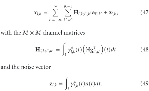
For the overall MPMC system including modulator (4), channel (44), and demodulator (5), the input-output rela-tion can be written as
xl,k= ∞
l=−∞ K−1
k=0
Hl,k;l,kal,k+zl,k, (47)
with theM×Mchannel matrices
Hl,k;l,k=
tγ ∗ l,k(t)
HgT
l,k
(t)dt (48)
and the noise vector
zl,k=
tγ ∗
l,k(t)n(t)dt. (49)
Here, the terms withl = landk = kcorrespond to in-tersymbol and intercarrier interference (ISCI). Furthermore, the off-diagonal elements inHl,k;l,kcorrespond tointerpulse
interference(IPI), which is specific to MPMC modulation. Conventional multicarrier designs typically aim at min-imizing all interference (ISCI), such that an approximate scalar input-output relation is obtained. For large channel spreadsρH, that is, for severe delay and Doppler spread, this requires a significant amount of redundancy, which in turn reduces spectral efficiency. The MPMC framework suggests a more general design approach which we call interference shaping. Here, IPI is partially tolerated at the receiver in or-der to allow further ISCI reduction. Mathematically, this can
7E{·}denotes expectation (ensemble averaging).
Hl,k el,k
al,k ×
xl,k
+ xl,k
Figure6: Equivalent vector model for MPMC transmissions.
be expressed via the equivalent input-output relation (see Figure 6)
xl,k=xl,k+el,k, withxl,k=Hl,kal,k, (50)
where the channel matrix corresponding to the “desired” re-ceive sequencexl,kis given by8
Hl,k
Hl,k;l,kD
. (51)
The 0/1-valued matrixDcharacterizes the intended inter-ference shaping by defining the IPI to be tolerated. All un-desired interference (ISCI, unun-desired IPI) and the noise are subsumed in the interference vectorel,k. If the receiver targets
at simple scalar equalization and thus tolerates no IPI, then D=I. Tolerating all IPI by using more sophisticated matrix equalizers corresponds toD =1(the all-one matrix). Note that, according to (50), ISCI and noise are always undesired.
6.3. Interference analysis
For the statistical analysis of (50), we assume that the num-ber of subcarriers is infinite (hence, our results provide up-per bounds on the interference power for systems with fi-nite number of subcarriers). Furthermore, we assume zero-mean i.i.d. transmit symbols al,k with correlation matrix
Ca E{al,kaHl,k}. Together with the WSSUS assumption,
this implies that the actual receive sequence xl,k, the
de-sired sequence xl,k, and the interference sequence el,k are
i.i.d. sequences with respective correlation matrices Cx E{xl,kxHl,k},CxE{xl,kxHl,k}, andCeE{el,keHl,k}. These
ma-trices are related as
Ce=Cx−Cx,x−CHx,x+Cx, (52)
whereCx,x E{xl,kxlH,k}. To obtain compact explicit
expres-sions for the above correlation matrices, we introduce the matrix cross-ambiguity function(cf. [32])
Aγ,g(τ,ν)
tγ(t)g
H(t−τ)e−j2πνtdt (53)
of the multipulsesg(t) andγ(t), and the periodized scatter-ing function
CH(τ,ν)
∞
l=−∞ ∞
k=−∞
CH(τ−lT,ν−kF). (54)
Note thatCH(τ,ν) depends on the TF lattice parametersT
andF. With these definitions, it can be shown that
Cx=
τ
νCH(τ,ν)
A∗γ,g(τ,ν)D
×Ca
Aγ,g(τ,ν)D
T dτ dν,
Cx=
τ
νCH(τ,ν)A
∗
γ,g(τ,ν)CaATγ,g(τ,ν)dτ dν
+σn2
tγ
∗(t)γT(t)dt,
Cx,x=
τ
νCH(τ,ν)A
∗
γ,g(τ,ν)Ca
Aγ,g(τ,ν)D
T dτ dν.
(55)
These expressions depend on the channel statistics (i.e., scat-tering functionCH(τ,ν) and noise varianceσ2
n), the
multi-pulsesg(t) andγ(t), and on the TF lattice parametersT,F. The multipulses and the lattice parameters can be designed to optimize system performance measures like the overall in-terference powerE{eHl,kel,k} =tr{Ce}[17].
6.4. Spectral efficiency
Instead of interference power, we aim at using spectral effi -ciency as performance measure. Based on the vector model (50), the mutual information ofal,k andxl,k assuming that
Hl,kis known at the receiver can be calculated as [33]
Il,k=log2det
I+Hl,kCaHHl,kCe−1
, (56)
where we made the simplifying assumptions thatal,kandel,k
are independent and Gaussian. Althoughal,kandel,kin
prac-tice are correlated, our independence assumption is relevant for receivers that do not exploit these correlations. Further-more, al,k andel,k will be approximately Gaussian if linear
precoding is used.
Due to the WSSUS assumption, theergodic mutual in-formationE{Il,k}is independent ofl,k. The (ergodic)
spec-tral efficiency in (bit/s/Hz) is obtained by normalization with
TF,ζ1/(TF)E{Il,k}. The expectation involved inζcannot
be evaluated explicitly. Since log2det(·) is convex, an upper bound is obtained from Jensen’s inequality [33],
ζ= 1
TFE
log2detI+Hl,kCaHHl,kCe−1 ≤ζmax
1
TFlog2det
I+EHl,kCaHHl,k Ce−1
.
(57)
Sincexl,k=Hl,kal,k, we have
EHl,kCaHHl,k =E
Hl,kal,kaHl,kHHl,k =Cx, (58)
and thus
ζmax= 1
TFlog2det
I+CxCe−1
. (59)
This expression can be easily evaluated for a channel with given scattering function by computingCx,Ceusing the
re-sults from the previous subsection. In our simulations, we
observed thatζmax typically is close toζ. The spectral effi
-ciency measureζmaxhas the advantage that it allows for fair
comparisons of MPMC (SPMC) systems with different lat-tice parametersT,Fand pulse numberM.
We caution the reader that the TF lattice constantsTand
Fenter (59) twice: explicitly in front of the log and implicitly via the SINR matrixCxCe−1(cf. (52) and (55)). While large T,Freduce the pre-log, it simultaneously increases the SINR.
7. NUMERICAL EXAMPLES
In this section, we provide design examples for MPMC sys-tems, analyze how MPMC system parameters and channel statistics influence spectral efficiency, and compare MPMC systems with conventional SPMC systems.
7.1. Simulation setup
The channel used in the simulations had a flat scattering functionCH(τ,ν)=1/ρHfor (τ,ν)∈[−τmax,τmax]×[−νmax, νmax] andCH(τ,ν)=0 else. Here,τmax,νmax, andρHare the
maximum delay, maximum Doppler, and channel spread, re-spectively.
The pulse designs presented are based on the methods introduced in Section 5. In all simulations, the prescribed multipulseg(t) consisted of the firstM = 4Hermite func-tions(the SPMC system considered for comparison used the first Hermite function, that is, a Gaussian pulse). This choice was motivated by the fact that these pulses possess the best possible TF localization, that is, their average time-bandwith product9 T
gFg achieves the minimum value of TgFg/M =
1/(4π) [32]. Good TF localization is known to be benefi-cial for reduced ISCI [9, 11, 19]. The scaling of the Her-mite functions was matched to the MPMC lattice parame-ters, Tg/Fg = T/F. The design of the MPMC system used M=4 and targets at interference shaping withD=1.
Based on the prescribed Hermite multipulse, biorthogo-nal multipulsesgα(t) andg−α(t) were calculated
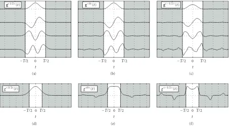
accord-ing to (38). The resultaccord-ing MPMC multipulses are depicted in Figures7(a)–7(c)forα =1/2 (prescribed Hermite mul-tipulse,TgFg/M = 1/(4π)),α = 0 (orthogonalized
multi-pulse,TgFg/M =1.13/(4π)), andα = −1/2
(biorthogonal-to-Hermite multipulse,TgFg/M=1.73/(4π)). Figures7(d)–
7(f)similarly depict the corresponding SPMC pulses which are much poorer localized10(their average time-bandwidth
product TgFg equals 1/(4π), 1.74/(4π), and 6.38/(4π) for α=1/2,α=0, andα= −1/2, resp.).
7.2. TF lattice parameters
We first investigate the dependence of ζmax on the
redun-dancy TF/M and the lattice ratio T/F for an orthogonal MPMC with transmit/receive multipulseg0(t).
9T2
g
tt2gH(t)g(t)dt/
tgH(t)g(t)dt,F2g
f f2GH(f)G(f)df /
fGH(f)G(f)df, whereG(f) denotes the Fourier transform ofg(t). 10For proper comparison of Figures7(a)–7(c)and7(d)–7(f), it should be
g<1/2>(t)
−T/2 0 T/2 t (a)
g<0>(t)
−T/2 0 T/2 t (b)
g<−1/2>(t)
−T/2 0 T/2 t (c)
g<1/2>(t)
−T/2 0 T/2 t (d)
g<0>(t)
−T/2 0 T/2 t (e)
g<−1/2>(t)
−T/2 0 T/2 t (f)
Figure7: MPMC multipulse for (a)α=1/2, (b)α=0, (c)α= −1/2, and SPMC pulse for (d)α=1/2, (e)α=0, (f)α= −1/2.
InFigure 8(a),ζmax is plotted versusTF/M ∈ [1.0125,
1.2] for different SNRs and channel spreads. In all cases, the lattice ratio wasT/F=τmax/νmax. As expected, large
redun-dancy, low SNR, and large channel spreads degrade spec-tral efficiency. The degradation due to channel dispersion is particularly pronounced for large SNR. The optimum re-dundancy that maximizes ζmax (marked with×) is seen to
range from≈1.0125 (for low SNR or low channel spread) to
≈1.0375 (for large SNR and large channel spread).
Spectral efficiency versus the normalized lattice ratio (T/F)/(τmax/νmax) with fixed redundancyTF/M =17/16 =
1.0625 is shown inFigure 8(b), again for various SNRs and channel spreads. The simulation confirms that for all chan-nel spreads and SNRs, the optimum TF lattice ratio equals
T/F=τmax/νmax, although the dependence ofζmaxonT/Fis
weak for lowρH. The same result, not shown, was obtained for the SPMC system using an orthogonalized Gaussian.
7.3. Biorthogonalization parameter
Next, we analyze how spectral efficiency depends on the pa-rameterα used to calculate the biorthogonal transmit and receive multipulses. Here,TF/M=1.0625,T/F=τmax/νmax,
andρH=0.0083.
The spectral efficiency ζmax for the MPMC system
and the SPMC system is shown in Figures 9(a) and 9(b), respectively, for several SNR values. For low SNR, the spectral efficiency of the MPMC and the SPMC system is maximized by choosingα=0, that is, orthogonal pulses amounting to matched filtering. For larger SNRs (i.e., interference-limited situations), however, the optimumαfor the MPMC system tends to−1/2, corresponding to a Hermite multipulse at the receiver and its biorthogonal multipulse at the transmitter.
This is intuitive since the localization of the transmit pulses is destroyed by the channel anyway, and hence the perfect local-ization of the Hermite multipulse is best exploited at the re-ceiver. With the SPMC system, the optimumαfor large SNR is slightly above 0. However,α=0 is close to optimum for all SNRs.
7.4. System comparison
Finally, we compare the spectral efficiencies of the MPMC system with orthogonalized Hermite multipulse, the SPMC system with orthogonalized Gaussian, and a conventional CP-OFDM system. All systems had redundancy TF/M =
17/16 and lattice ratioT/F=τmax/νmax. The SNR was 30 dB
and maximum delay and Doppler were varied in a range such that√F/Tτmax∈[0, 0.1], and
√
T/Fνmax∈[0, 0.1].
We note that pulse optimization procedures exist both for SPMC systems [11,34] and MPMC systems [17]. Fur-thermore, [18,34,35] discuss the practically relevant design and optimization of finite-duration pulses. System compar-isons using optimized pulses are, however, beyond the scope of this paper.
Figure 10 shows that for all channel parameters, the MPMC system outperforms the SPMC system. In almost all cases, the MPMC and SPMC systems have largerζmax than
the CP-OFDM system. The latter is advantageous only for small Doppler and for delays below the CP duration. For