R E S E A R C H
Open Access
Segmentation algorithm via Cellular Neural/
Nonlinear Network: implementation on
Bio-inspired hardware platform
Fethullah Karabiber
1, Pietro Vecchio
2and Giuseppe Grassi
2*Abstract
The Bio-inspired (Bi-i) Cellular Vision System is a computing platform consisting of sensing, array sensing-processing, and digital signal processing. The platform is based on the Cellular Neural/Nonlinear Network (CNN) paradigm. This article presents the implementation of a novel CNN-based segmentation algorithm onto the Bi-i system. Each part of the algorithm, along with the corresponding implementation on the hardware platform, is carefully described through the article. The experimental results, carried out forForemanandCar-phonevideo sequences, highlight the feasibility of the approach, which provides a frame rate of about 26 frames/s. Comparisons with existing CNN-based methods show that the conceived approach is more accurate, thus representing a good trade-off between real-time requirements and accuracy.
Keywords:Cellular Neural/Nonlinear Networks, image segmentation, Bio-inspired hardware platform
1. Introduction
Due to the recent advances in communication technolo-gies, the interest in video contents has increased signifi-cantly, and it has become more and more important to automatically analyze and understand video contents using computer vision techniques. In this regard, seg-mentation is essentially the first step toward many image analysis and computer vision problems [1-15]. With the recent advances in several new multimedia applications, there is the need to develop segmentation algorithms running on efficient hardware platforms [16-18]. To this purpose, in [16] an algorithm for the real-time segmenta-tion of endoscopic images running on a special-purpose hardware architecture is described. The architecture detects the gastrointestinal lumen regions and generates binary segmented regions. In [17], a segmentation algo-rithm was proposed, along with the corresponding hard-ware architecture, mainly based on a connected component analysis of the binary difference image. In [18], a multiple-features neural-network-based segmenta-tion algorithm and its hardware implementasegmenta-tion have
been proposed. The algorithm incorporates static and dynamic features simultaneously in one scheme for seg-menting a frame in an image sequence.
Referring to the development of segmentation algo-rithms running on hardware platforms, in this article the attention is focused on the implementation of algo-rithms running on the Cellular Neural/Nonlinear Net-work (CNN) Universal Machine [5-7]. This architecture offers great computational capabilities, which are suita-ble for complex image-analysis operations in object-oriented approaches [8-10]. Note that so far few CNN algorithms for obtaining the segmentation of a video sequence into moving objects have been introduced [5,6]. These segmentation algorithms were only simu-lated, i.e., the hardware implementation of these algo-rithms is substantially lacking. Based on these considerations, this article presents the implementation of a novel CNN-based segmentation algorithm onto the Bio-inspired (Bi-i) Cellular Vision System [9]. This sys-tem builds on CNN type (ACE16k) and DSP type (TX 6×) microprocessors [9]. The proposed segmentation approach focuses on the algorithmic issues of the Bi-i platform, rather than on the architectural ones. This algorithmic approach has been conceived with the aim of fully exploiting both the capabilities offered by the
* Correspondence: [email protected]
2
Dipartimento di Ingegneria dell’Innovazione, Università del Salento, 73100 Lecce, Italy
Full list of author information is available at the end of the article
Bi-i system, that is, the analogprocessing based on the
ACE16k as well as the digitalprocessing based on the
DSP. We would point out that, referring to the segmen-tation process, the goal of our approach is to find mov-ing objects in video sequences characterized by almost static background. We do not consider in this article still images or moving objects in a video captured by a camera located on a moving platform, where the back-ground is also moving.
The article is organized as follows. Section 2 briefly revises the basic notions on the CNN model and the Bi-i cellular vBi-isBi-ion archBi-itecture. Then the segmentatBi-ion algorithm is described in detail (see the block diagram in Figure 1). In particular, in Section 3, the motion detection is described, whereas Section 4 presents the edge detection phase, which consists of two blocks, the preliminary edge detection and the final edge detection. In Section 5, the object detection block is illustrated. All the algorithms are described from the point of view of their implementation on the Bi-i, that is, for each task it is specified which templates (of the CNN) run on the ACE16k chip and which parts run on the DSP. Finally, Section 6 reports comparisons between the proposed approach and the segmentation algorithms described in [3] and [5], which have been also implemented on the Bi-i Cellular Vision System.
2. Cellular Neural/Nonlinear Networks and Bio-Inspired Cellular Vision System
Cellular Neural/Nonlinear Networks represent an infor-mation processing system described by nonlinear ordin-ary differential equations (ODEs). These networks, which are composed of a large number of locally con-nected analog processing elements (called cells), are described by the following set of ODEs [1]:
˙
xij(t) =−xij(t) +
kl∈N¯rAij,klykl(t) +
kl∈N¯rBij,klukl(t) +Iij (1)
yij(t) =f(xij(t)) = 0.5xij(t) + 1−xij(t)−1 (2)
wherexij(t) is the state, yij(t) the output, and uij (t)
the input. The constant Iij is the cell current, which
could also be interpreted as a space-varying threshold
[19]. Moreover,Aij,klandBij,klare the parameters
form-ing the feedback templateAand the control templateB,
respectively, whereas kl∈N¯r is a grid point in the
neighborhood within the radius ¯rof the cellij[20].
Since the cells cooperate in order to solve a given computational task, CNNs have provided in recent years an ideal framework for programmable analog array com-puting, where the instructions are represented by the templates. This is in fact the basic idea underlying the CNN Universal Machine [1], where the architecture combines analog array operations with logic operations
(therefore named asanalogic computing). A global
pro-gramming unit was included in the architecture, along with the integration of an array of sensors. Moreover, local memories were added to each computing cell [1]. The physical implementations of the CNN Universal Machine with integrated sensor array proved the physi-cal feasibility of the architecture [11,12].
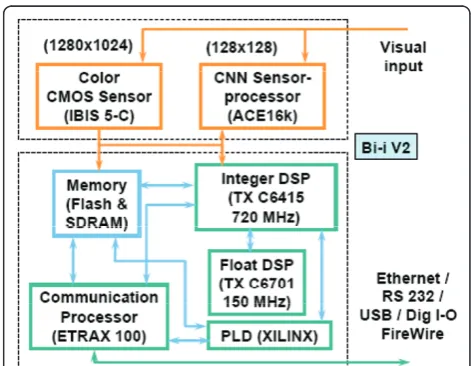
Recently, a Bio-inspired (Bi-i) Cellular Vision System has been introduced, which combines Analogic Cellular Engine (ACE16k) and DSP type microprocessors [9]. Its algorithmic framework contains several feedback and automatic control mechanisms among the different pro-cessing stages [9]. In particular, this article exploits the Bi-i Version 2 (V2), which has been described in detail in reference [9]. The main hardware building blocks of this Bi-i architecture are illustrated in Figure 2. It has a color (1280 * 1024) CMOS sensor array (IBIS 5-C), two high-end digital signal processors (TX C6415 and TX
Figure 1Block diagram of the overall segmentation algorithm.
Figure 2The main hardware building blocks of the Bi-i cellular
C6701), and a communication processor (ETRAX 100) with some external interfaces (USB, FireWire, and a general digital I/O, in addition to the Ethernet and RS232).
Referring to the Analogic Cellular Engine ACE16k, note that a full description can be found in [12]. Herein, we recall that it represents a low resolution (128 * 128) grayscale image sensor array processor. Thus, the Bi-i is a reconfigurable device, i.e., it can be used as a monocu-lar or a binocumonocu-lar device with a proper selection of a high-resolution CMOS sensor (IBIS 5-C) and a low-resolution CNN sensor processor (ACE16k) [9].
Two tools can be used in order to program the Bi-i Vision System, i.e., the analogic macro code (AMC) and the software development kit (SDK). In particular, by using the AMC language, the Bi-i Vision System can be programmed for simple analogic routines [9], whereas the SDK is used to design more complex algorithms (see Appendix). Referring to the image processing library (IPL), note that the so-called TACE_IPL is a library developed within the SDK. It contains useful functions for morphological and grey-scale processing in the ACE16k chip (see Appendix). Additionally, the Bi-i
V2 includes an InstantVision™library [9].
Finally, note that through the article, the attention is focused on the way the proposed segmentation algo-rithm is implemented onto the Bi-i Cellular Vision Sys-tem. Namely, each step of the algorithm has been conceived with the aim of fully exploiting the Bi-i cap-abilities, i.e., the processing based on the ACE16k chip as well as the processing based on the DSP.
3. Motion detection
This section illustrates the motion detectionalgorithm
(Figure 1). Let YiLP and YiLP- 3 be two gray-level images,
processed by a low-pass (LP) filtering, and let YMD
i be
the motion detection (MD) mask. In order to implement the motion detection onto the Bi-i, the first step (see
Equation 3) consists in computing the difference
between the current frame YLP
i and the third preceding
frame YiLP- 3 using the ACE16k chip. The indicesi andi
-3 denote that the frames i-2 and i-1 are skipped.
Namely, the analysis of the video sequences considered through the article suggests that it is not necessary to compute the difference between successive frames, but it is enough every three frames. However, as far as the algorithm goes, every frame is evaluated, even though the reference frame is three frames older. This means
that we need to store every frame, because the framei+
1 requires framei-2 as a reference.
Then, according to Step 2 in Equation 3, positive and
negative threshold operations are applied to the
difference image via theConvLAMtoLLM function [13]
implemented on the ACE16k chip. This function (included in the SDK) converts a grey-level image stored in the local analog memory (LAM) into a binary image stored in the local logic memory (LLM). Successively, the logic OR operation is applied between the output of the positive threshold and the output of the negative threshold. The resulting image includes all the changed pixels.
step 1−compute the difference between the framesYLP i andYLPi−3
step 2−apply a positive and negative threshold step 3−delete irrelevent pixel
(3)
Finally, according to Step 3, thePoint Remove function
[13] (running on the ACE16k) is used for deleting irrele-vant pixels not belonging to the contour lines. The
out-put of the algorithm is the MD mask YMD
i , which
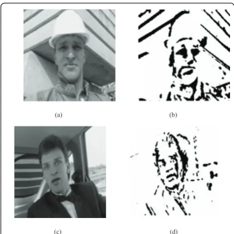
entirely preserves the moving objects. Figure 3a, c shows
a sample frame of Foreman and Car-phone video
sequences, respectively, whereas Figure 3b, d shows the
corresponding motion detection mask YiMD.
4. Edge detection
The proposed edge detection phase consists of two
blocks, the preliminary edge detectionand thefinal edge
detection (see Figure 1). In the first block, the
(a) (b)
(c) (d)
Figure 3Motion detectionfor two benchmark video sequences.
(a)Foremansample frame;(b)its corresponding mask YMD i ;(c)
Car-phonesample frame;(d)its corresponding maskYMD
i . The
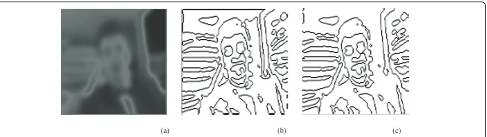
based dual window operator (proposed by Grassi and Vecchio [10]) is exploited to reveal edges as zero-cross-ing points of a difference function, dependzero-cross-ing on the minimum and maximum values in the two windows. After this preliminary selection of edge candidates, the second block enables accurate edge detection to be obtained, using a technique able to highlight the discon-tinuity areas.
4.1. Preliminary edge detection
The aim of this phase is to locate the edge candidates. The dual window operator is based on a criterion able to localize the mean point within the transition area between two uniform luminance areas [10]. Thus, the first step consists in determining the minimum and maximum values in the two considered windows. Given
the input image YLP
i , we consider for each sample
s∈YiLP(x,y)two concentric circular windows, centered
ins and having radiusr andR, respectively (r < R). Let
MRand mR be the maximum and minimum values of
YLP
i within the window of radius R, and letM
r
andmr
be the maximum and minimum values within the
win-dow of radiusr [10]. Note that, for the video-sequences
considered through the article, we have taken the values
r = 1 pixel and R= 2 pixels. For each sample s, let us
define the difference function D(s) = a1 (s) - a2 (s),
wherea1(s) =MR- Mranda2 (s) =mr-mR. By
assum-ing thatsis the middle point in a luminance transition,
the relationship a1 (s) = a2 (s) holds. In the case of
noise, the change in the sign of the difference function
D(s) is a more effective indicator of the presence of a
contour [10]. Since D(s) approximates the directional
derivative of the luminance signal along the gradient
direction [10], the relationshipD(s) = 0 is equivalent to
find the flex points of luminance transitions. In particu-lar, we look for zero-points and zero-crossing points of
D(s). Hence, the introduction of a threshold is required,
so that samplesssatisfy the condition -threshold <D(s)
<threshold. Successively, edge samples are detected
according to the following algorithm [10]:
step1−computeD(s) =α1(s)−α2(s)
step2−foreachs= (x0,y0)so that−threshold<D(s)<threshold
ifD(s) = 0 thensis edge elseifD(s)≥0 and
D(x0−1,y0)<0 orD(x0+ 1,y0)<0
orD(x0,y0−1)<0 orD(x0,y0+ 1)<0
thensis edge.
(4)
In other words, by applying the algorithm (4) to the sample itself and to the four neighboring samples, preli-minary edge detection is achieved. In order to effectively implement (4) onto the Bi-i, the first step is the
compu-tation ofD(s), which can be realized using
order-statis-tics filters. They are nonlinear spatial filters that enable maximum and minimum values to be readily computed onto the Bi-i platform. Their behaviors consist in
ordering the pixels contained in a neighborhood of the current pixel, and then replacing the pixel in the centre of the neighborhood with the value determined by the selected method. Therefore, these filters are well suited to find the minimum and maximum values in the
neigh-borhood of the current pixel. The implementation of D
(s) gives the images in Figure 4a, c for Foreman and
Car-phone, respectively.
Going to Step 2, thethresholdis implemented on the
ACE16k using the ConvLAMtoLLMfunction. Then, the
relationship -threshold <D(s)<threshold is satisfied by
implementing the operationsinversion, OR and
inver-sion again onto the ACE16k chip. Note that we look for
samples s so that D(s) = 0. Additionally, we look for
samples s satisfying the condition that D (s) ≥ 0 but,
simultaneously, D(s) must be negative in a cross-shape
neighborhood of s. Specifically, at least one of the four
conditionsD(x0± 1,y0± 1) < 0 must be satisfied. Thus,
we need to computeD(s) by exploring proper
neighbor-hoods of (x0,y0), two examples of which are reported in
Figure 4e, f. Note that the object is represented by black pixels, while the background is represented by white pixels. The exploration of proper neighborhoods in the
image D(s) can be done using the morphologicdilate4
function, which performs four-connectivity (cross-mask) binary dilatation on the ACE16k [13]. Note that Figure
4e contains an edge, since the conditions D(x0-1,y0) < 0
andD(x0,y0-1) < 0 are satisfied. On the other hand,
Fig-ure 4f does not contain any edge, sinceD (s) > 0 in the
neighborhood of (x0,y0). Referring toForeman, the edges
selected by implementing the condition -threshold <D
(s)<threshold are reported in Figure 4g, whereas those
selected by exploring proper neighborhoods of (x0,y0)
are reported in Figure 4h. In particular, note that Figure 4h highlights that there are some flat areas characterized by some edges. Finally, the OR operation between the
images in Figure 4g, h provides the imageYiprel
repre-senting the preliminary edge detection. To this purpose,
Figure 4b, d depicts the imagesYiprel for Foreman and
Car-phonevideo sequences, respectively.
4.2. Final edge detection
The aim of this phase is to better select the previously detected edges. Referring to the previous section, note
that the zeros ofD(s) are not only flex points of
lumi-nance transitions, but also the set of pixels having a neighborhood where luminance is almost constant [10]. Since noise causes small fluctuations, these fluctuations
may generate changes in the sign of D that would be
MRand mRidentify the direction of maximum slope in
the neighborhood of s [10]. Therefore, by suitably
exploiting MR and mR, we first need to generate a
matrix S, which takes into account the slope of the
luminance signal. Then, a threshold gradient operation
is applied toS, with the aim to obtain a gradientmatrix
G. Namely, the final objective is to obtain an image that
includes all the edges selected by the gradient operation
(i.e., Yigrad). Successively, the image Yigrad needs to be
cleaned and skeletonized, in order to reduce all the edges to one-pixel thin lines. The image reporting the
(a) (b)
(c) (d)
(e) (f)
(g) (h)
Figure 4Preliminary edge detectionalgorithm.(a)matrixD(s) forForeman;(b)corresponding outcomeYprel
i ;(c)matrixD(s) forCar-phone;(d)
corresponding outcomeYprel
i ;(e)neighborhood of (x0,y0) containing and edge;(f)neighborhood of (x0,y0) not containing any edge;(g)edges
final edge detection, indicated by Yifinal edge(s), can be obtained by applying the following algorithm:
step 1−for each pixels= (x0,y0)∈Dcomputes(s) =
MR(s) ifD(s)≥0 mR(s) ifD(s)<0
step 2−apply athreshold gradientoperation onS(s) to obtainG(s) step 3−for each pixels∈Yipre1(s) computeY
grad i (s) =
⎧ ⎪ ⎨ ⎪ ⎩
Yipre1(s) ifs∈G(s) ∅ifs∈/G(s) step 4−skeletonizeYigrad(s) to obtainY
final edge
i (s)
(5)
In order to effectively implement the algorithm (5)
onto the Bi-i, at first the matrix D(s) is processed by
means of the ConvLAMtoLLM function, which
imple-ments the threshold ‘zero’ on D(s). Then, the pixels
in D that correspond to D (s) ≥ 0 assume the
maxi-mum value of the luminance signal (within the
win-dow of radius R) and generate the image MR
D.
Similarly, the pixels in D that correspond toD(s) < 0
assume the minimum value of the luminance signal
and generate the image mRD. Then, in order to
imple-ment the matrix S(s), we need the following new
switch template:
A= ⎡ ⎢ ⎣
0 0 0 0 −1 0 0 0 0
⎤ ⎥
⎦ B=
⎡ ⎢ ⎣
0 0 0 0 2.2 0 0 0 0
⎤ ⎥
⎦I= 0 (6)
The matrix S(s) is generated onto the ACE16k chip,
where MR
D is used as input, mRD as statewhereas the
output of the‘zero’threshold is used as mask. Referring
to the template (6), we have chosen the name switch
since the image S(s) is obtained by ‘switching’between
MR(s) andmR(s), depending on the mask values. Note
that the template (6), by providing the matrix S(s),
enables the slope of the luminance signal to be taken
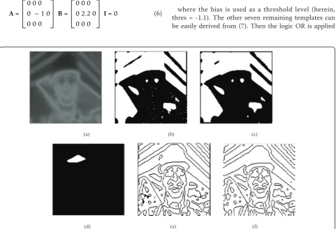
into account. The experimental result of S(s) are
reported in Figures 5a and 6a for Foreman and
Car-phone, respectively.
Then, according to the algorithm (5), we need to
implement thethreshold gradientoperation onto the
Bi-i. This can be done using a sequence of eight templates, applied in eight directions N, NW, NE, W, E, SW, S, and SE. For example, referring to the NW direction, the following novel template is implemented on the ACE16k:
A= ⎡ ⎢ ⎣
0 0 0 0 1 0 0 0 0 ⎤ ⎥
⎦ B=
⎡ ⎢ ⎣
−3 0 0 0 3 0 0 0 0
⎤ ⎥
⎦I= thres (NW) (7)
where the bias is used as a threshold level (herein,
thres=-1.1). The other seven remaining templates can
be easily derived from (7). Then the logic OR is applied
(a) (b) (c)
(d) (e) (f)
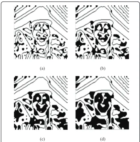
Figure 5Final edge detectionforForeman.(a)the matrixS(s);(b)the imageG(s);(c)output of theprunefunction;(d)output of thehollow
template;(e)edges selected by the gradientYgrad
i ;(f)final resultY
final edge
to the eight output images in order to obtain a single
image, which is denoted byG(s) (see Figure 5b). Note
thatG stands for gradient, given that it represents the
output of the threshold gradient (7). However, the
image Gneeds to be cleaned, since it usually contains
some open lines (see the upper left-side in Figure 5b).
These open lines can be deleted by applying the prune
template:
A=
⎡ ⎢ ⎣
0 0.5 0 0.5 3 0.5 0 0.5 0
⎤ ⎥
⎦ B=
⎡ ⎢ ⎣
0 0 0 0 0 0 0 0 0 ⎤ ⎥
⎦ I=−1.5. (8)
The output of theprunefunction is reported in Figure
5c, where it can be seen that the open line in the upper left-side part has been partially deleted. Note that the
prune function also enables the back part in Figure 5c to become more compact (i.e., the white dots in the
black part have disappeared). Then, thehollowtemplate
reported in [13] has to be applied. This template, run-ning on the ACE16k chip, enables the concave locations of objects to be filled. In order to achieve this objective, thehollowtemplate needs to be applied. The output of thehollowis shown in Figure 5d. The white part in Fig-ure 5d indicates that the corresponding part in the
image S(s) does not contain information related to
edges. Since the hollow is time-consuming, it is useful to carry out this operation by exploiting the great com-putational power offered by the CNN chip.
Finally, by using theswitchtemplate (6) with input =
Yiprel(s), state =∅(i.e., the white image) and mask =
G(s), it is possible to obtain the imageYigrad(s), which
includes all the edges selected by the gradient opera-tion (see Figures 5e and 6b). In order to skeletonize
Yigrad(s) and reduce all the edges to one-pixel thin
lines, the skeletonization function (included in the
TACE_IPL library) is implemented on the ACE16k chip. Then, in order to complete open edges (if any)
we can use the dilationand erosionfunctions included
in the TACE_IPL. Specifically, we first apply the
dila-tion function, and then theerosion function. These two
functions are applied from three to six times, depend-ing on the video sequence under consideration. Finally, the last step lies in deleting the remaining open lines.
By applying theprune template (8), the final edges can
be obtained, as shown by the images Yifinal edge(s)
reported in Figures 5f and 6c for Foreman and
Car-phone, respectively.
5. Object detection
The proposed object detection phase can be described
using the following iterative procedure:
BEGIN :k= 1
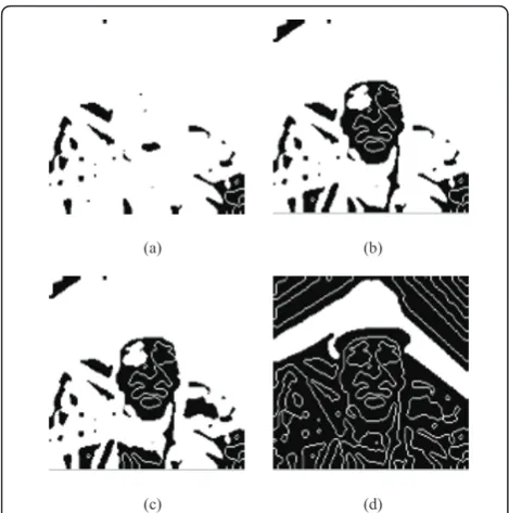
step 1− − −fill closed edges (notsimultaneously) in the inverted image ofYfinal edgei to obtainY fill(k) i
step 2− − −detect changes betweenYfill(k)i and (−Yfinal edgei ) to obtainYichanges(k) step 3− − −fill closed edges inYfill(k)i to obtainY
fill(k+1)
i .
step 4− − −thicken edges inYifill(k+1)to obtainYidilation(k+1). step 5− − −detect objects inYidilation(k+1)to obtainY
recall(k+1) i
step 6− − −detect changes betweenYirecall(k+1)andYichanges(k) if changes= 0 and if the extracted objectYextracted(k+1)i is a moving object,
then updateYchanges(k)i step 7− − −assignk=k+ 1
step 8− − −ifYfill(k)i =Yfill(k+1)i go to step 3 else END
(9)
First, the followinghole-fillertemplate is implemented
on the ACE16k:
A= ⎡ ⎢ ⎣
0.1 0.2 0.1 0.2 1 0.2 0.1 0.2 0.1
⎤ ⎥
⎦ B=
⎡ ⎢ ⎣
0 0 0 0 1 0 0 0 0 ⎤ ⎥
⎦ I= 1.3. (10)
This template is applied to the inverted image of
Yifinal edge with the aim to fill all the holes. Figure 7
depicts the outputs of thehole-filler after different
pro-cessing times, with the aim to show the system behavior when the processing times are increased. Note that the
hole-fillerhas to be applied in a recursive way, in order to fill more and more holes. However, differently from Figure 7 that has an explanatory purpose, we need to apply this template by slowly increasing the processing
(a) (b) (c)
Figure 6Final edge detectionforCar-phone.(a)the matrixS(s);(b)edges selected by the gradientYgrad
i ;(c)final resultY
final edge
times. Namely, if we slowly increase the processing times, it is possible to highlight at the most two closed objects at a time, so that these objects can be extracted
in the next steps. As a consequence, the hole-fillerplays
an important role: by slowly filling the holes in a mor-phological way, it enables the closed objects to be extracted in the next steps of the algorithm.
In order to implement the second step, the logic XOR
is applied between the output of the hole-filler (i.e.,
Yifill (k)) and the inverted image of Yifinal edge. Note that the logic XOR enables changes in the two images to be detected. This logic function returns a 1 only if both operands are logically different, otherwise it returns a 0. Bitwise logic XOR is executed on the ACE16k between
LLM1 and LLM2 (binary images stored in the Local Logic Memories 1 and 2). Herein, the outcome of the
XOR is the binary image Yichanges (k), which locates the
changes between the two images Yifill (k) and
−Yifinal edge. The output of the XOR is shown in Fig-ure 8a.
According to Step 3, thehole-fillertemplate is applied
to Yifill (k), with the aim to obtain Yifill (k+1). Referring to
Step 4, the morphologic dilate function is utilized to
thicken the contours within the image Yifill (k+1). The
result of thedilatefunction, which performs binary
dila-tation onto the ACE16k, is indicated by Yidilation (k+1)
and is shown in Figure 8b.
According to Step 5, we need to detect the remaining
objects in Yidilation (k+1). This can be done using the
recalltemplate
A= ⎡ ⎢ ⎣
0.5 0.5 0.5 0.5 3 0.5 0.5 0.5 0.5
⎤ ⎥
⎦B=
⎡ ⎢ ⎣
0 0 0 0 3 0 0 0 0 ⎤ ⎥
⎦ I= 3 (11)
where the image Yidilation (k+1) is used asinputand the
image Yifinal edge as state. In order to show how the
recall template works, Figure 9 shows its output after
different processing times. Note that therecalltemplate
has to be applied in a recursive way. In particular, by increasing the processing times, note that more and more objects are recalled (see Figure 9).
However, differently from Figure 9 that has an expla-natory purpose, herein we need to apply this template by slowly increasing the processing times. Namely, in order to guarantee a satisfying total frame rate, we need to recall few objects at a time, so that the processing times due to the recall template are not large. In this way, the slow recursive application of the recall template
(a) (b)
(c) (d)
Figure 7Behaviour of thehole-fillertemplate forForeman.(a)
output after about 15μs;(b)output after about 30μs;(c)output after about 45μs;(d)output after about 60μs.
(a) (b)
Figure 8Object detection algorithm forForeman.(a)detected changesYchanges (k)
i ;(b)dilated image Y
dilation (k+1)
does not affect the overall system performances. In con-clusion, the recall template plays an important role: by taking into account the image containing the final edge (state), it enables the objects enclosed in the dilated
image (input) to be recalled and subsequently extracted.
Now, by applying the recall template (11) using the
image in Figure 8b as inputand the image in Figure 5f
asstate, the image reported in Figure 10a is obtained.
This image, indicated by Yirecall (k+1), is constituted by
groups of objects. In order to obtain new objects at each iteration, we need to detect the changes between the
imagesYirecall (k+1)and Yichanges (k), as indicated by Step
6. To this purpose, we can apply the logic XOR between
Yichanges (k) and Yichanges (k). If changes are detected, we need to check whether the extracted object belongs to the moving objects. This operation is implemented by exploiting the AND operation between the output of
previous XOR and the motion detection mask YMD
i .
The output of the AND is indicated by Yiextracted (k+ 1).
For example, the objects extracted after the first itera-tion are shown in Figure 10b. Finally, the extracted
object Yiextracted (k+ 1) is used to update the image
Yichanges (k), with the aim of obtaining Yichanges (k+1). This iterative procedure is carried out until all the objects are extracted. Namely, the procedure ends when
the condition Yifill (k) = Yifill (k+1) is achieved for two
consecutive iterations. Figures 8 and 10 summarize
some of the fundamental steps of the object detection
algorithm for Foremanvideo sequence. Similar results
have been obtained forCar-phone video sequence.
6. Discussion
We discuss the results of our approach by making com-parisons with previous CNN-based methods illustrated in [3] and [5]. We would remark that the comparison between the proposed approach and the methods in [3] and [5] is homogeneous, since we have implemented all these techniques on the same hardware platform (i.e., the Bi-i). At first, we compare these approaches by visual inspection. By analyzing the results in Figures 11 and 12, it can be noticed that the proposed technique provides more accurate segmented objects than the ones obtained by the techniques in [5] and [3]. For example, the analysis of Figure 11a suggests that the proposed
approach is able to detect man’s mouth, eyes, and nose.
Note the absence of open lines too. The methods depicted in Figure 11b, c do not offer similar capabil-ities. Referring to Figure 12a, note that we have obtained
an accurate result, since man’s mouth, eyes, and nose
(a) (b)
(c) (d)
Figure 9Behaviour of therecalltemplate for Foreman.(a)
output after about 50μs;(b)output after about 85μs;(c)output after about 170μs;(d)output after about 650μs.
(a) (b)
Figure 10 Object detection algorithm for Foreman.(a) group of objects Yrecall (k+1)
i ; (b) new objects after the first iteration
are detected, along with some moving parts in the back of the car. Again, the approaches depicted in Figure 12b, c do not reach similar performances. It can be con-cluded that, by exploiting the proposed approach, the edges are much more close to the real edges with respect to the method in [5] and [3].
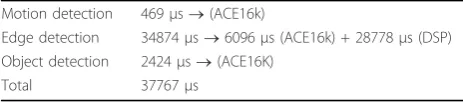
Now an estimation of the processing time achievable by the proposed approach is given in Table 1. Note that themotion detectionand theobject detectionphases can be fully implemented onto the ACE16k chip, whereas the edge detection phase requires that some parts be implemented on the DSP (see Section 4). The sum of
the processing times of the different phases is 37767μs,
which gives a frame rate of about 26 frames/s.
Note that the computational load is mainly due to the
DSP in theedge detection phase (28778μs) and,
specifi-cally, to the presence of the order-statistics filters. On the other hand, these filters are requested to implement the dual window operator, which is in turn required to achieve accurate edge detection, as explained in [10]. Namely, edge detection is a crucial step for segmentation. If we detect edge accurately, we can segment the images correctly. If we analyze the result in reference [5], we note that the authors use a threshold gradient algorithm, which is not particularly suitable for edge detection. On the other hand,
the dual window operator is one of the best edge detector (see [10]), even though its implementation is time con-suming. Referring to the processing times measured on the Bi-i for the methods in [3] and [5], their values are
13861 and 5254μs, respectively. The corresponding frame
rates are 72 and 190 frames/s, respectively, while our approach gives 26 frames/s. Thus, the segmentation meth-ods in [3] and [5] are faster than the proposed approach, even though they are less accurate, as confirmed by Fig-ures 11 and 12. Anyway, we believe that 26 frames/s can be considered a satisfying frame rate achievable by the proposed approach, since it represents a good trade-off between accuracy and speed.
Finally, we would point out that, while we have con-ducted this research, a novel Bio-inspired architecture called Eye-RIS vision system has been introduced [21]. It is based on the Q-Eye chip [21], which represents an evolution of the ACE family with the aim to overcome the main drawbacks of ACE chips, such as lack of robustness and large power consumption. Our plan is to implement the segmentation algorithm developed herein on the Eye-RIS vision system in the near future. To this purpose, note that one of the authors (F. Karabiber) has already started to work on the Eye-RIS vision system, as is proof by the results published in [22].
(a) (b) (c)
Figure 11Foremanvideo sequence.(a)segmentation by our method;(b)segmentation by the method in [5];(c)early segmentation in [3].
(a) (b) (c)
7. Conclusion
This article has presented the implementation of a novel CNN-based segmentation algorithm onto a Bio-inspired hardware platform, called Bi-i Cellular Vision System
[9]. This platform combines theanalogprocessing based
on the ACE16k processor [11] as well as thedigital
pro-cessing based on the DSP. The proposed experimental results, carried out for some benchmark video sequences, have shown the feasibility of the approach, which provides a satisfying frame rate of about 26 frames/s. Finally, comparisons with the CNN-based techniques in [5] and [3] have highlighted the accuracy of the proposed method.
Appendix
The software development kit (SDK) is a set of C++ libraries to be used for Bi-i programming. Some parts of the SDK are based on classes defined in the BaseData
module of the InstantVision™ libraries. The SDK is
designed to be used together with Code Composer Stu-dio from Texas Instruments (http://www.ti.com/).
The TACE_IPL is an image processing library (IPL) for ACE16k. It contains two function groups for proces-sing images: morphological operations and gray scale operations. The constructor of this class initializes the needed instruction group and writes corresponding IPL templates to the ACE16k.
Note that all the details about the SDK, the
InstantVi-sion™ libraries and the TACE_IPL can be found at:
http://www.analogic-computers.com/Support/ Documentation/
Alternatively, the Bi-i programming guide (which includes the SDK and the TACE_IPL) can be requested at: [email protected]
List of abbreviations
AMC: Analogic Macro Code; Bi-i: Bio-inspired; CNN: Cellular Neural/Nonlinear Network; IPL: image processing library; LP: low pass; LAM: local analog memory; LLM: local logic memory; MD: motion detection; ODEs: ordinary differential equations; SDK: software development kit.
Author details
1Department of Chemistry, University of North Carolina, Chapel Hill, NC,
27599-3290, USA2Dipartimento di Ingegneria dell’Innovazione, Università del
Salento, 73100 Lecce, Italy
Competing interests
The authors declare that they have no competing interests.
Received: 25 May 2011 Accepted: 21 September 2011 Published: 21 September 2011
References
1. LO Chua, T Roska, inCellular Neural Networks and Visual Computing– Foundations and Applications((Cambridge University Press, 2002), Cambridge, UK), ISBN 0521652472
2. C-Y Chen, J-C Wang, J-F Wang, Y-H Hu, motion entropy feature and its applications to event-based segmentation of sports video. EURASIP J Adv Signal Process.2008(8) (2008). (Article ID 460913)
3. P Arena, A Basile, M Bucolo, L Fortuna, An object-oriented segmentation on analog CNN chip. IEEE Trans CAS-I50(7), 837–846 (2003). doi:10.1109/ TCSI.2003.813985
4. MAA Dewan, MJ Hossain, O Chae, An adaptive motion segmentation for
automated video surveillance. EURASIP J Adv Signal Process.2008(13) (2008). (Article ID 187413)
5. A Stoffels, T Roska, LO Chua, Object-oriented image analysis for very-low-bitrate video-coding systems using the CNN Universal Machine. Int J Circuit Theory Appl.25, 235–258 (1997). doi:10.1002/(SICI)1097-007X(199707/08) 25:43.0.CO;2-Q
6. A Stoffels, T Roska, LO Chua, On object-oriented video-coding using the CNN Universal Machine. IEEE Trans CAS-I,43(11), 948–952 (1996) 7. T Roska, A Rodriguez-Vazquez, Towards visual microprocessors. Proc IEEE.
90(7), 1244–1257 (2002). doi:10.1109/JPROC.2002.801453
8. G Grassi, LA Grieco, Object-oriented image analysis using the CNN Universal Machine: new analogic CNN algorithms for motion compensation, image synthesis and consistency observation. IEEE Trans CAS-I.50(4), 488–499 (2003). doi:10.1109/TCSI.2003.809812
9. A Zarandy, C Rekeczky, Bi-i: a standalone ultra high speed cellular vision system. IEEE Circuit Syst Mag.5(2), 36–45 (2005)
10. G Grassi, E Di Sciascio, LA Grieco, P Vecchio, New object-oriented segmentation algorithm based on the CNN paradigm. IEEE Trans CAS-II. 53(4), 259–263 (2006)
11. G Linan, S Espejo, R Dominguez-Castro, A Rodriguez-Vazquez, ACE4k: an analog I/O 64x64 visual microprocessor chip with 7-bit analog accuracy. Int J Circuit Theory Appl, 30, 89–116 (2002)
12. A Rodriguez-Vazquez, G Linan-Cembrano, L Carranza, E Roca-Moreno, R Carmona-Galan, F Jimenez-Garrido, R Dominguez-Castro, SE Meana, ACE16k: the third generation of mixed-signal SIMDCNN ACE chips toward VSoCs. IEEE Trans CAS-I51(5), 851–863 (2004). doi:10.1109/TCSI.2004.827621 13. http://cnn-technology.itk.ppke.hu/
14. J-K Ahn, D-Y Lee, C Lee, C-S Kim, Automatic moving object segmentation from video sequences using alternate flashing system. EURASIP J Adv Signal Process.2010(14). (Article ID 340717)
15. C-Y Hsu, C-H Yang, H-C Wang, Multi-threshold level set model for image segmentation. EURASIP J Adv Signal Process.2010(8) (2010). (Article ID 950438)
16. J Kim, T Chen, A VLSI architecture for video-object segmentation. IEEE Trans CAS Video Technol.13(1), 83–96 (2003). doi:10.1109/TCSVT.2002.808082 17. N Ranganathan, R Mehrotra, A VLSI architecture for dynamic scene analysis.
Comp Vis Graph Image Process.5, 189–197 (1991) 18. J Kim, T Chen, Multiple feature clustering for image sequence
segmentation. Pattern Recog Lett.22, 1207–1217 (2001). doi:10.1016/S0167-8655(01)00053-8
19. M Brucoli, L Carnimeo, G Grassi, A global approach to the design of discrete-time cellular neural networks for associative memories. Int J Circuit Theory Appl.24(4), 489–510 (1996). doi:10.1002/(SICI)1097-007X(199607/08) 24:43.0.CO;2-F
20. G Grassi, On discrete-time cellular neural networks for associative memories. IEEE Trans CAS-I,48(1), 107–111 (2001). doi:10.1109/81.903193
21. A Rodríguez-Vázquez, R Domínguez-Castro, F Jiménez-Garrido, S Morillas, J Listán, L Alba, G Liñán-Cembrano, L Carranza, The Eye-RIS CMOS vision system, inAnalog Circuit Design, (Berlin, Germany, 2007), pp. 15–32 22. F Karabiber, P Arena, L Fortuna, S De Fiore, S Vagliasindi, S Arik,
Implementation of a moving target tracking algorithm using Eye-RIS Vision System on a mobile robot. J Signal Process Syst (2010)
doi:10.1186/1687-6180-2011-69
Cite this article as:Karabiberet al.:Segmentation algorithm via Cellular Neural/Nonlinear Network: implementation on Bio-inspired hardware
platform.EURASIP Journal on Advances in Signal Processing20112011:69.
Table 1 Execution times for the proposed segmentation algorithm
Motion detection 469μs®(ACE16k)
Edge detection 34874μs®6096μs (ACE16k) + 28778μs (DSP)
Object detection 2424μs®(ACE16K)

![Figure 11 Foreman video sequence.(a) segmentation by our method; (b) segmentation by the method in [5]; (c) early segmentation in [3].](https://thumb-us.123doks.com/thumbv2/123dok_us/1146317.1143852/10.595.61.540.573.702/figure-foreman-sequence-segmentation-method-segmentation-method-segmentation.webp)