~
WY-l
00
Display Terminal
Maintenance Manual
WYSE
WY-100 DISPLAY TERMINAL
MAINTENANCE MANUAL
PUBLICATION HISTORY
Date
10-82 03-84
Notes
InitiaL PubLication (PreLiminary) Second Edition
RELATED PUBLICATIONS
Wyse No. TitLe
88-003-01 WY-100 DispLay TerminaL Reference ManuaL
TRADEMARKS
WY-100 is a registered trademark of Wyse TechnoLogy.
COPYRIGHT NOTICE
Copyright @ 1982, 84, Wyse TechnoLogy. ALL Rights Reserved WorLdwide. No part of this pubLication may be reproduced without the express written permission of Wyse TechnoLogy.
SAFETY WARNING
The terminaL power cabLe is suppLied with a safety ground. Do not use the ter~inaL with an ungrounded outLet. Disconnect the power cabLe from the terminaL before removing the top cover for any reason.
Dangerous voLtages are present when the terminaL is on and may remain after the power is off. Be extremeLy cautious. Do not work aLone.
The internaL phosphor of the CRT <cathode ray tube) is toxic. Wear safety goggLes and rubber gLoves whenever the CRT is handLed. If the tube breaks, exposing skin or eyes to the phos-phor, immediateLy rinse the affected area with coLd water and consuLt a physician.
DISCLAIMER
No representation or warranties are made regarding the contents of this document, and any impLied warranties or fitness for any particuLar appLication are discLaimed.
The specification and information are subject to change without prior notification. The right to revise this document without obLigation to notify any person or organization is aLso reserved.
FCC WARNING: This equipment generates, uses, and can radiate radio frequency energy, and if not instaLLed and used in accordance with the instruction manuaL, may cause interference to radio communications. It has been tested and found to compLy with the Limits for a CLass A compu-ting device pursuant to Subpart J of Part 1S of FCC RuLes, which are designed to provide reasonabLe protection against such interference when operated in a commerciaL environment. Operation of this equipment in a residentiaL area is LikeLy to cause interference, in which case the user, at his own expense, wiLL be required to take what-ever measures may be required to correct the interference.
SECTION I 1.0 2.0 2.1 2.2 2.3 3.0 3.1 3.1 .1 3.1. 2 3.1. 3
3.1. 4
3.2 3.2.1 3.2.2 3.2.3 3.2.4 3.3 3.3.1
SECTION II
1.0 2.0 2.1 2.2 2.3 3.0 3.1 3.2 3.3
SECTION III
1.0 2.0 3.0 4.0 4.1 4.2 4.3 4.4 5.0
TABLE OF CONTENTS
Page LOGIC BOARD MODULE
I nt rodu c t; on •••••••••••••••••••••••••••••• ,a • • • 1-1
Operating Parameters ••••••••••••••••••••••••••• 1-1 Physical Dimensions . • . . • • . . • • . • . • • . . . • . . . 1-1 Power Supply Requirements •••••••••••••••••••••• 1-1 Connector Information •••••••••••••••••••••••••• 1-2
Functional Description ••••••••••••••••••••••••• 1-4 Microprocessor Controller •••••••••••••••••••••• 1-4 8039 M;crocomputer ••••.•••..••••••••••••.•••••• 1-4 DispLay Memory ••••••••••••••••••••••••••••••••• 1-7 Program Memory ••••••••••••••••••••••••••••••••• 1-7 Communications and Data Buffer ••••••••••••••••• 1-7 Video Circuits . . . • . . . 1-8 CRT ControLLers •••••••••••••••••••••••••••••••• 1-8 Dot Clock and Dot Serializer •••••••••••••••••• 1-10 Character ROM ••••••••••••••••••••••••••••••••• 1-10 Attributes Synchronization and Generation ••••• 1-11 Asynchronous Communications Interface ••••••••• 1-11 Baud Rate Generation •••••••••••••••••••••••••• 1-11
KEYBOARD MODULE
I nt rodu c t; on ••.••••••.•••••.••••••••••••.•••••• 2-1 Operating Parameters ••••••••••••••••••••••••••• 2-1 PhysicaL Dimensions •.•••.••.•..•.•..•...•.•.•.. 2-1 Power Supply Requirements •••••••••••••••••••••• 2-1 Connector Information •••••••••••••••••••••••••• 2-1
Functional Description ••••••••••••••••••••••••• 2-1 Co L umn Decoder ••••••••••••••••••••••••••••••••• 2-3 Row Se lee tor ••••. ~ ••••••• ~ .••••••••••• ' •.•••••• • 2-3
Keyswitch Matrix ••••••••••••••••••••••••••••••• 2-3
MONITOR/POWER SUPPLY BOARD
Theory of Operation •••••••••••••••••••••••••••• 3-1
CRT ••••••••••••••••••••••••••••••.••••.•••••••• 3-2 Power Transformer •••••••••••••••••••••••••••••• 3-2 Monitor/Power Supply PCB ••••••••••••••••••••••• 3-2 +5 Vo l t Supp Ly ••••••••• ~ •••••••••••••••••••••• • 3-2 +13.5 Volt SuppLy •••••••••••••••••••••••••••••• 3-2 +12 Va l t Supp ly . . . • . . . • . . . 3-2
-12 Volt SuppLy •••••••••••••••••••••••••••••••• 3-3
Horizontal Deflection Circuits ••••••••••••••••• 3-3
Page SECTION III (continued)
6.0 Vertical Deflection Circuit •••••••••••••••••••• 3-3
7.0 Video AmpLifier •••••••••••••••••••••••••••••••• 3-3
7.1 Procedure for Disconnecting the
Monitor/Power Supply PCB ••••••••••••••••••••• 3-3 7.2 Procedure for Installing the Monitor/PS to
the TerminaL Base •••••••••••••••••••••••••••• 3-4 7.3 Procedure for Adjusting the Monitor/PS ••••••••• 3-5 7.4 Procedure for Display Geometry Adjustment •••••• 3-6
A
B
C
D
E
F
G
H
Figure 1 Figure 2 Figure 3 Figure 4 Figure 5 Figure 6
Figure A-1 Figure A-2 Figure B-1 Figure B-2 Figure C-1
Figure C-2
Figure D-1
contents 2
APPENDICES
PC ASSY Logic Board 99-004-01 REV E Part Number and Description
Keyboard PCB 99-003-01 REV B Part Number and Description
Monitor/PS PCB 99-002-01 REV T Part Number and Description
Monitor/Power Supply PCB ASSY 99-002-02 REV N
Monitor/Power Supply PCB ASSY 99-002-03 REV C
Troubleshooting Flowcharts
Notice
Current Loop Option
ILLUSTRATIONS .
Logic Board Block Diagram •••••••••••••••••••••• 1-5 Microprocessor Timing •••••••••••••••••••••••••• 1-6 Dot V; dec T; m; ng ••••••••••••••••••••••••••••••• 1-9 Frame Video Timing ••••••••••••••••••••••••••••• 1-9 Keyboard Block Diagram ••••••••••••••••••••••••• 2-2 System Wiring Diagram •••••••••••••••••••••••••• 3-1
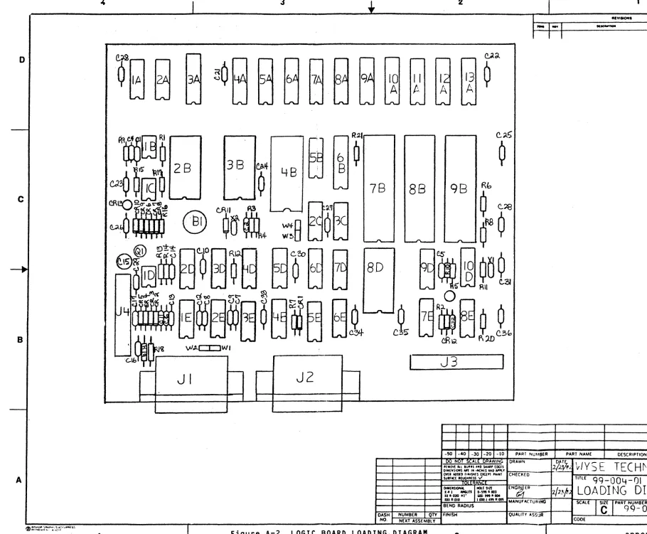
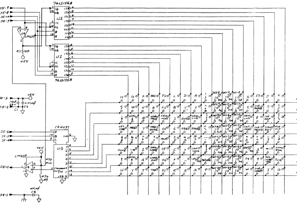
Logic Circuit Diagram •••••••••••••••••••••••••• A-3 Logic Board Loading Diagram •••••••••••••••• A-4/A-5 Keyboard Schematic ••••••••••••••••••••••••• B-2/B-3 Keyboard Loading Diagram ••••••••••••••••••• B-4/B-5 Monitor/Power Supply Board 99-002-01
Load; n9 D; ag ram ••••••••••••••••••••••••.••••• C-4 Monitor/Power Supply 99-002-01 Schematic
D; ag ram •••••••••••••••••••••••••••••••••••••• C-5 Monitor/Power Supply 99-002-02 Loading
Figure D-2
Figure E-1
Figure E-2
Figure F-1 Figure F-2 Figure F-3 Figure F-4 Figure F-S Figure F-6
Figure F-7 Figure F-8
Page
Monitor/Power Supply 99-002-02 Circuit
0; ag ram •••••••••••••••••••••••••••••••••••••• D-5 Monitor/Power Supply 99-002-03 Loading
D; ag ram •••••••••••••••••••••••••••••••••••••• E-5 Monitor/Power Supply 99-002-03 Schematic
D; ag ram •••••••••••••••••••••••••••••••••• E-6/ E-7 Block Diagram for Troubleshooting •••••••••••••• F-2 No Power Troubleshooting Flowchart, Part 1 ••••• F-3 No Power Troubleshooting Flowchart, Part 2 ••••• F-4 No Power Troubleshooting Flowchart, Part 3 ••••• F-S No Video Troubleshooting Flowchart ••••••••••••• F-6 No Brightness Control Troubleshooting
FLowe hart •••••••••••••••••••••••••••••••••••• F-7 No Horizontal Drive Troubleshooting Flowchart •• F-8 No Vertical Drive Troubleshooting FLowchart •••• F-9
Section I
LOGIC BOARD MODULE
1.0 !~IRQ2Y£I!Q~
The Logic board moduLe performs aLL of the terminaL Logic functions. These can be divided into four major parts: micropro-cessor controLLer, video timing, communication interface, and keyboard interface.
The microprocessor controLLer contains program ROM, dispLay and buffer RAM, I/O, and address I/O seLections.
The video timing fetches data from the dispLay memory, converts it into a dispLayabLe format, and generates aLL the necessary timing signaLs for interfacing with the monitor/power supply moduLe.
The communication interface does seriaL-to-paraLLeL data format conversion, provides baud rate generation and controL signals for an RS-232 modem port and a serial printer port.
The keyboard interface is the link between the microprocessor and the keyboard module. It aLLows the microprocessor to scan the key matrix and the DIP switch settings on the keyboard.
2.1 PHYSICAL DIMENSIONS
Size (L x W x D)
=
6" x 7" x 0.05" (15.38cm x 17.95cm x 0.13cm)2.2 POWER SUPPLY REQUIREMENTS
DC POWER: Standard:
+5 VDC +- 5% @ 1A
+12 VDC +- 10% @ 20 MA
-12 VDC +- 10% @ -0.001 MA
With 20 MA Current +5 VDC +- 5% @ 1 A
+12 VDC +- 10% @ 50 MA
-12 VDC +- 10% @ -0.001 MA
With 2nd Page Option: + 5 VDC +- 5% @ 1.25 A +12 VDC +- 10% @ 20 MA -12 VDC +- 10% @ -0.001 MA Loop Option:
+5 VOC +12 VDC +--12 VDC
+-5% @ 1. 25 A
10% @ 50 MA 10% @ -0.001 MA
AC POWER:
120 VAC @ 1 A 240 VAC @ 0.5 A
2.3 CONNECTOR INFORMATION
J1
=
RS-232 MODEM PORTConnector and Pin Assignment
J 1-1 J1-2 J1-3 J1-4 J1-5 J1-6 J1-7 J1-8 J1-9 J1-10 J1-11 J1-12 J1-13 J1-14 J1-15 J1-16 J1-17 J1-18 J1-19 J1-20 J1-21 J1-22 J1-23 J1-24 J1-25
J2
=
PRINTER PORTConnector and Pin Assignment
J2-1 J2-2 J2-3 J2-4 J2-5 J2-6 J2-7 J2-8 J2-9 J2-10 J2-11 J2-12
logic board module 1-2
Signal Name
GND (AA) TXD (BA) RXD (BB) RTS (CA) CTS (CB)
GND (AB)
oeD (CF) +12 V +12 VA DINRET DOUTRET +12 VA +12 V
DTR (CD)
Signal Name
PGND
PRXD
PGND
Description
ShieLd Ground Transmit Data Receive Data Request to Send CLear to Send
N/C
SignaL Ground
Data Carrier Detect +12 VDC
20 MA Current Source Data In Return
Data Out Return
20 MA Current Source +12 VDC
N/C N/C Nle N/C Nle
Data TerminaL Ready
N/C N/C N/C N/C N/C Description
ShieLd Ground
Nle
Transmit Data
N/C N/C N/C
SignaL Ground
Connector and
Pin Assignment Signal Name Description
J2-13 N/C
J2-14 N/C
J2-15 N/C
J2-16 N/C
J2-17 N/C
J2-18 N/C
J2-19 N/C
J2-20 PDTR Data TerminaL Ready
J2-21 N/C
J2-22 NIC
J2-23 N/C
J2-24 N/C
J2-25 N/C
J3 = KEYBOARD INTERFACE
Connector and
Pin Assignment Signal Name Description
J3-1 GND ShieLd Ground
J3-2 GND SignaL Ground
J3-3 +5 V +5 V
J3-4 SCAN 2 Scan Line 2
J3-5 SCAN 1 Scan Line 1
J3-6 SCAN
a
Scan Linea
J3-7 SCAN 3 Scan Line 3
J3-8 SCAN 5 Scan Line 5
J3-9 SCAN 6 Scan Line 6
J3-10 SCAN 4 Scan Line 4
J3-11 KEY IN Key Input
J4 = MONITORIPOWER SUPPLY INTERFACE
Connector and
Pin Assignment Signal Name Description
J 4-1 GND ShieLd Ground
J4-2 GND ShieLd Ground
J4-3 +12 V +12 VDC
J4-4 -12 V -12 VDC
J4-5 GND SignaL Ground
J4-6 +5 V +5 VDC
J4-7 VDR VerticaL Synch
J4-8 GND SignaL Ground
J4-9 HDR HorizontaL Synch
J4-10 VIDEO Video SignaL
The logic board is functionally divided into four parts: micro-processor controller, video timing, communication interface, and keyboard interface. See Figure 1 for a block diagram of the Logic board.
3.1 MICROPROCESSOR CONTROLLER
The microprocessor controller consists of an 8039 microcomputer, display and buffer memory, program memory, I/O and address decoder, and support circuits that are connected directly to the processor bus. (See Figure 2 for the timing diagrams and Figure A-1 for the schematic).
3.1.1 8039 Microcomputer (98)
The 8039 microcomputer is an 8-bit microprocessor with 128 bytes of internal RAM, two 8-bit I/O ports and an on-chip timer/ counter. It operates with a 10.376 MHz crystal (X1) which is also used for baud rate generation in the data communication interface section, resulting in a 1.48 microsecond instruction time for one-cycle instructions.
The data bus lines DBO through DB7 are used for transfer tions and data bytes bet wen 8039 (98) and program ROM display and buffer RAM (4A-13A), CRT controllers (7B, UART (48). They are multiplexed into address lines
instruction fetch and external memory access.
instruc-(2B/3B),
88) and during
I/O ports P10 through P16 are used for outputting row and column addresses during keyboard scan. P17 is a beLL enable signal. It is used by the microprocessor to sound the bell. It is also used to provide an audio feedback effect to the keyboard by generating a click when a key is pressed on the keypoard.
The second I/O port is used for I/O and memory devices selection. The lower four lines P20-P23 also contains the four high order bits of address A8-A11 during external memory access. In device selection mode, P20 indicates whether the data byte on the bus is a command or a data byte when accessing the CRT controllers. In memory selection mode, P20 contains the address bit A8. P21-P23 contain the address bits A9-A11, respectively; and they are meaningful onLy in the memory seLection mode. P24 seLects either the display RAM (6A-13A) or buffer RAM (4A, SA) for externaL RAM access. P2S enabLes the read/write operation of the UART. P27 selects the output data from UART to be transmitted through either the RS-232 modem port (J1) or the serial printer port (J2).
ACE, PSIN,
[0, and WR are output controL signaLs.AtE
is a cLock signaL used to Latch the address bits during a memory or I/O cycLe.PSEN
occurs onLy during a fetch to externaL program
r-o
to
-I,
n
CT
o
III
.,
a.
:3
o
a. c
r
-eo
I
VI
CONTROL
~8276
LOGIC
I - - -_ _ ~CRT CNTRLR
1
VIDEO
CIRCUITS
8276
-
CRT CNTRLR
VIDEO
I----~"
HRT
I----~'
VRT
'---.---~
Figure 1. IOOIC OOAID BUXI< DIJGWol
2651
UART
I
BUFFER
J
~
1
~
0 to
~.
n cr
0
C»
.,
0-;a 0
0-r;:
~
It
~
I
0-ALE
ooE-- 150ms~
I
I
~<---2~0~0-m-s--~>---~Oms~
--?> 70ms~
-.,/
h'"'""7~""7'jX
ADDRESSXT!17
//lX~_---Iol.OPA..L.CTA-....I.IOi.IJ.JUT
_ _--JX
DATA I N~1ZT17/u
~ 350 ms
~QID1:==~
_____________ 4_8Q __ID~S
_____________~~
~40ms-+-
--+
160 IDS +-P23-P20 P 2 H i Q X , - - - A - l l - - - A - 8 - - - X P 2 3 - P20
(EXT. MEMORY CYCLE)
~ 300 ms ~
memory. ~.
W[,
are the read and write signaLs for strobing data onto the bus.TO
is a feedback signaL from the keyboard indicating whether a particuLar key is being depressed. It is an active high signaL.T1 is a status signaL randomLy monitored by the processor. this signal is inserted, it indicates that a character has received by the UART (88) and is ready to be fetched by processor.
When been
the
!NT
is an interrupt request signaL asserted by the CRT controLLer (78) when screen refresh is required. The processor responds to the interrupt request by initiating a DMA process which transfers a bLock of 80 characters from the display RAM (6A-13A) to the CRT controLlers (78, 88).RESET input signal provides a means for initializing the processor upon power-on. It is held at logic low for at least 30 milliseconds after the power supply is in tolerance.
3.1.2 DispLay Memory (6A-13A)
The dispLay memory consists of 2K (4K) bytes of memory, or 4 (8) 2114 1K x 4 static memory components (6A-13A) external to the processor. It is accessed by the processor to refresh the screen and to update the text. The lower address lines are Latched by an 8-bit Latch (3A) on the rising edge of ALE during each external memory cycLe. A two-to-four decoder (58) is used to decode the upper address Lines A10 and A11 into a 1K byte memory bLock, and to select a pair of 2114 memory components.
3.1.3 Program Memory (28/38)
The terminal program is stored in a 4K x 8 2732 (28) EPROM. It contains the display driver, the communication interface firm-ware and the keyboard scanner. AlternativeLy, the 2732 can be substituted with two 2716s (28, 38) by slightly modifying the control line VPP/A11 and address line CEo
3.1.4 Communications and Data 8uffer
A 1K byte buffer consists of two 2114 static memory chips (4A, 5A) used as a buffer RAM area for storing characters received from communication ports, soft function key codes and descrip-tions on the screen. This 1K memory address space overlaps the 4K display RAM area. The I/O port P24 of 8039 is used to select either the buffer RAM or display RAM access.
3.2 VIDEO CIRCUITS
The video circuits can be divided into four parts: CRT controLLers; cLock, characters cLock, and dot seriaLizer; char-acter ROM; and attribute synchronization and generation. For detaiLed video timing information see Figures 3 and 4.
3.2.1 CRT Controllers (78, 88)
Two InteL 8276 CRT controLLers are used to generate the scan Line count, the character count, the horizontaL and verticaL timing signaLs, and the visuaL attributes. The 8276 CRT controLLer contains two 80-character on-chip row buffers: one is used as a circuLating row buffer during each scan Line dispLay; the other is used to store prefetched characters for the next dispLay row.
The
RD
input signaL is never used by the 8039 processor and is permanentLy tied to Logic high.The
C7P
input signaL when used in conjunction withCS
whether the input information on DBO-DB7 is a command byte.
indicates or data
The data Lines DBO-DB7 are Linked to the 8039 processor bus for transferring program parameters and dispLay characters from tWe processor to the two CRT controLLers.
The CS signaL is asserted when the 8276s are seLected by the processor for setting timing parameters. It is aLso used to reset the J-K fLipfLop (SE) after each character row refresh.
BRDY
is an interrupt request signaL asserted by the 8276 (7B) at the beginning of each row refresh. The processor responds toBRDY
by initiating a DMA process which transfers a bLock of 80 characters from the dispLay RAM to the"row buffers inside of the two 8276s. TheBRDY
signaL, when asserted, causes the foLLowing CPU read operations to become write operations to the 8276s.The
Wi
signal is derived from two signaL sources: the write signaL from the CPU when the screen is not being refreshed, or the read signaL from the CPU when the screen is being refreshed. It is a controL signaL used either to strobe data into the row buffers or to set the command/data parameters.The ASCII codes of the row buffers are outputted on signaL Lines CCO-CC6. SignaLs
ceo
through CC6 and the scan Line count LCO-LC3 index into the character ROM, and convert an ASCII code into its corresponding dot pattern to be dispLayed on the screen.BS is the buffer seLection signaL. It enabLes the current write operation to access the character row buffers inside the 8276s. GPAO, GPA1, VSP, RVV, and HLGT are the visuaL attributes vaLid during each character dispLay cycLe. They are used for
~1l36~
DOT CLOCK
~ 541.136 ms
'>
CHARACTER -E-- 270.568 ms
--71
I~
______
~
CLOCK
(CCLK) ~150 ms~ .---_ _ _ _ _ _ _ _ - . .
CHARACTER
MW~
VALID~h0<
__________ _
CODE
(CCO-CC6) < 350 ms
>
CHARACTER /////L////////////77/////////xy"'-AL----ID)0/#
///~ff//
~#
ff
#2>C
ROM<
275 ms ~ATTRIBUTE
i/7//'//Z//7//7/dA ____
""-_-
_-...:..:-VA:U:D====)@77§///#//;0( _______ _
CODESFigure 3. oor VIDED T:IMJN:;
CHARACTER CLOCK
r- (CCLK) ~ 54.1125 ms
0
HDR 60 Hz ~
fl
ms=?j
!SIC
...
n
+--16.6666 ms f"r
0-VDR 60 Hz
~
J.J0 ~
1.1?f35
msQ)
..,
Q.~ 54.1125 ms ~
:3 f"t"
0
HDR 50 Hz
It
ms~
,,~
Q. ~
c
19.9999 ms ~
r- -+-- t"r
tD
VDR 50 Hz 14.
r
P57 ms7f
,,~
+--...
I
-0 Figure 4. FRAME
vm:m
blanking, underlining, video suppression, reverse video, and highlighting display characters.
HRTC
andVRTC
are the horizontal and vertical drive signals. They are used by the monitor/power supply moduLe to controL the sweep of the Light beam on the screen. TheHRTC
pulse is triggered by a 555 one-shot (18) which generates an approximate blanking time of 24 microseconds independent of AC operating frequency. The HRTC signal has a period of 54.1125 ms. TheVRTC
duty-cycle is programmed by the CPU. It has a blanking time of 1.19035 ms when the screen is refreshed at 60 Hz rate, and 14.2857 ms when the screen is refreshed at 50 Hz rate.The
CCCK
is a 50% duty-cycLe, 1.848 MHz character clock used by the 8276s and the synchronizer (3D). It is the basic timing signal for synchronizing the internal circuitry of the two 8276s.3.2.2 Dot Clock and Dot Serializer
The character dot timing is generated by an oscilLator circuit using an 18.48 MHz crystal. This 18.48 MHz, 50% duty-cycLe signaL is the clock source for both the dot seriaLizer (70) and the character clock generator (90). The character clock generator (90) divides the dot cLock by 10 since each character celL is 10 dots wide. It aLso provides the appropriate timing signal to reload the dot serializer (70) with the next character pattern~
and to reinitiaLize itself.
The dot serializer (70) converts an 8-bit pattern of a character matrix from the character ROM (80) into 10 seriaL dots to be displayed on each scan Line. The two extra dots are generated by repeating the first dot twice after the eighth dot is displayed. This scheme aLlows horizontal Lines of two adjacent graphic characters to be connected.
3.2.3 Character ROM (8D)
The basic character celL is a 10-dot by 11-scan Line rectangle. Within the cell is the 7 x 8 character, surrounded by one dot on the left side for horizontaL spacing, two scan Lines beLow for Lower case descending, and one scan Line above for row-to-row spacing.
ALL dots and aLL character scan Lines in the matrix are used for graphics characters. Each character scan Line segment is stored in ROM as an 8-bit word. Seven of the bits (01 through 07) are used for the character dots, and the eighth (DO) is used to specify dot-extension for graphic characters. If a graphic char-acter scan is extended, two dots are jammed into the dot seriaL-izer (70) after the first eight bits are Loaded. This results in a continuous Line across the entire scan Line of the character ceLL.
3.2.4 Attributes Synchronization and Generation
The attributes associated with each character are vaLid during the character cycLe. They must be latched by an 8-bit Latch (6B) however, because the character ROM access time exceeds one character cycLe time and the outputs of the character ROM must be synchronized with the attribute signaLs.
The output signaL
ceo
of the second 8276 (8B) is OR'd with the haLf-intensity attribute from the first 8276 (7B). This signaL is used as a protect character mark for each ASCII code stored in the dispLay RAM. This resuLts in every protected character being dispLayed as dim.3.3 ASYNCHRONOUS COMMUNICATIONS INTERFACE
The terminaL data communcations are centered around the 2651 UART (4B). This chip performs the seriaL-to-paraLLeL data con-version for RS-232 data communication, as weLL as detecting parity, framing, and overrun errors. In addition, signaLs RTS,
CfS,
orR,
DSR, DCD
are handLed by the 2651.Buffers 1488 (2E) and 1489A (1E) provide the necessary LeveL conversions for the RS-232 data communications. The 470pf capa-citors used on each driver and receiver are used for sLew rate controL, and aLLow the datacomm Lines to be driven to 9600 baud.
3.3.1 Baud Rate Generation
The baud rates are generated by the 2651 UART from a 10.1376 MHz cLock source. The programmabLe baud rates supported by the 2651 and their respective error rates are as foLLows:
Baud Rate
50 70 110 134.5 150 300 600 1200 1800 2000 2400 3600 4800 7200 9600
Percent Error
0.016
0.253
Note: The percent error does not include the crystal error.
Section II
KEYBOARD MODULE
1.0 !H!!Q2Y~!!QH
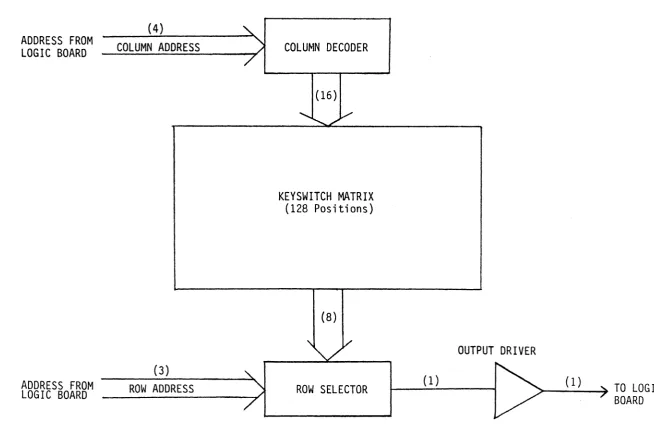
The keyboard moduLe scans the keys and DIP switches, and returns their status to the Logic board moduLe (see Figure 5).
2.1 PHYSICAL DIMENSIONS
Size (L x W x D)
=
20.5" x 7.1" x 1.3" (20.5cm x 18.20cm x 3.33cm)2.2 POWER SUPPLY REQUIREMENTS
DC POWER:
+5 VDC + 5% @ 20 MA
2.3 CONNECTOR INFORMATION
Connector and Pin Assignment
J 5-1 J5-2 J5-3 J5-4 J5-5 J5-6 J5-7 J5-8 J5-9 J5-10 J5-11
SignaL Name
GND GND +5 V SCAN 2 SCAN 1 SCAN
a
SCAN 3 SCAN 5 SCAN 6SCAN 7 KEY In
3.0 fYH~!!QHAb 2s~~!!e!!QH
Description
ShieLd Ground SignaL Ground +5 V
Scan Line 2 Scan Line 1 Scan Line
a
Scan Line 3 Scan Line 5 Scan Line 6Scan Line 4 Key Input
The keyboard moduLe consists of two 3-to-8 decoders, an 8-to-1 data seLector, a voLtage comparator, three 8-position DIP switches with diode, a 14-pin maLe connector, and 105 mechanicaL momentary key switches.
7f:"
ID
'<
0-o
C»
.,
a. a o a.
c
r -ID
IV
I
IV
ADDRESS FROM
LOGIC BOARD
ADDRESS FROM
LOGIC BOARD
(4)
COLUMN ADDRESS
(3)
ROW ADDRESS
~
"
/COLUMN DECODER
/
(16)
... V
KEYSWITCH MATRIX
(128 Positions)
(8)
"\.LV'
"-
(1)"
/ROW SELECTOR
/
Figure 5. KEYIDAm BUXX DnGRl\M
OUTPUT DRIVER
~
(1)/
...
3.1 COLUMN DECODER
The signaLs presented on J5-7 through J5-10 are decoded into 1-of-16 coLumn signals.
3.2 ROW SELECTOR
One of the eight rows of the keyboard matrix is selected by the three encoded signals on J5-4 through J5-6. The eight rows are pulled up by 10K resistors to +5 V. If a key switch is pressed or a DIP switch is cLosed and its row and column position is selected by the code presented on J5-4 through J5-10, a Logic 0 is fed back to the Logic board on J5-11.
3.3 KEY SWITCH MATRIX
The keyboard has 105 keys and three 8-position DIP switches. Left SHIFT and right SHIFT are eLectricaLLy tied together on the key switch matrix. Each of the 24 DIP switches, the shift keys, and CTRL has a diode attached to it. The diodes are to prevent ghost keys when more than three keys are pressed simultaneousLy.
Section III
MONITOR/POWER SUPPLY BOARD
1.0 !tl~2BI
2f
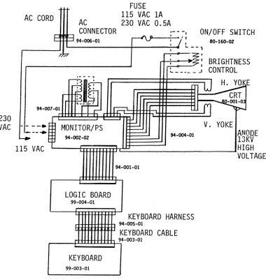
2e~BA!12~The monitor/power suppLy unit of the WY-100 dispLay terminal consists of a CRT, a power transformer, a printed circuit board and various harnesses. See Figure 6: System Wiring Diagram and Figure D-2: Circuit Diagram.
230
VAC
AC CORD
FUSE
115 VAC 1A
230 VAC 0.5A
AC
CONNECTOR
1-- -,
I 1
I,
ON/OFF SWITCH
94-006-01
•..
--,
80-160-02
---.~.~;"-"~2·
,
,BRIGHTNESS
~ _____ J
CONTROL
94-007';-Oil!!!!!::M::§::e:~~affffr=m===~
- - - -.
V. YOKE .
--+
~
__94-002-02
~~~iR~~~~~~~9:4-:OO:4-:01~
______
JANODE
13KV
HIGH
115 VAC
.VOLTAGE
94-001-01
LOGIC BOARD
99-004-01
KEYBOARD HARNESS
~lm~W3 94-005-01
q
KEYBOARD CABLE
r_-E!!!!!!~!5-i94-oo3-01
KEYBOARD
99-003-01
Figure 6. SYSTEM WIRING DIAGRAM
2.0
SRI
The CRT is a 12-inch 90-degree infLection tube with a 20mm neck diameter. It is mounted directLy to the bezeL of the terminaL via four screws.
3.0
---
POWER TRANSFORMER---The power transformer, mounted to the right-rear of the terminaL chassis, accepts 115 VAC (or 230 VAC) from the power Line and transforms these voLtages to Lower LeveLs required by the power suppLy section of the monitor/power suppLy pcb.
The transformer has two Low voLtage windings. One of them sup-pLies the +5 voLt power suppLy consisting of U2, Q2 and other components. The second Low voLtage winding suppLies the +13.5 voLt power suppLy consisting of U1, Q1 and other components as weLL as the +12 V suppLy (U3) and the -12 V suppLy (U4).
The monitor/power suppLy pcb is mounted verticaLLy on the right side of the dispLay unit chassis. This pcb contains the power suppLy, horizontaL and verticaL defLection circuits and the video circuits of the terminaL.
4.1 +5 VOLT SUPPLY
This circuit consists of U2 (see Appendix G), Q2 and other mis-ceLLaneous components. U2 is an integrated circuit voLtage reguLator. VR1 is used to adjust the output of this circuit to +5 VDC at pin 6, J4. Q2 is the output transistor of the power suppLy. R23, R24 and R31 Limit the output and protect the voL-tage reguLator under short-circuit conditions.
4.2 +13.5 VOLT SUPPLY
This circuit consists of U1 (see Appendix G), Q1, and other components. U1, is aLso an integrated circuit voLtage reguLa-tor. VR2 is used to adjust the ouput of the suppLy to 13.5 voLts. R3, R27, R32, and R33 form a current Limiting circuit that protects the power suppLy under short-circuit conditions.
4.3 +12 VOLT SUPPLY
This circuit consists of U3 (see Appendix G), a three-terminaL voLtage reguLator ICO. It suppLies +12 voLt DC (at pin 3, J4) to the Logic board assembLy.
4.4 -12 VOLT SUPPLY
This circuit consists of U4, (see Appendix G), a three-terminal voLtage reguLator IC. It suppLies - 12 VoLt DC (at pin 4, J4) to the Logic board assembLy.
A horizontaL drive signaL is suppLied by the Logic board assembLy to pin 9 of J4. This signaL drives Q3 and T1 which in turn suppLy the driving signaL for the horizontaL ouput transistor QS. QS, with its associated components, provide horizontaL defLection and other operating voLtages for the CRT.
For the defLection functions, L1 provides width adjustments, L2 is the Linearity correction coiL and C20 is the S-shaping capa-citor.
T2 is the fLyback transformer and is voLtage (+12 KV) for the CRT anode, focusing voLtages for the tube. The ampLifier is aLso generated by T2.
6.0 VERTICAL DEFLECTION CIRCUIT
---
---
---used to generate the high as weLL as the biasing and suppLy voLtage of the video
us
is an integrated vertical defLection circuit (see Appendix G). A verticaL drive signaL is provided by the Logic board assembLy at pin 7, J4. This signal provides the vertical synchronization signaL required by US. The vertical defLection yoke is driven directLy by US and its associated circuitry. VRS provides adjust-ment for raster height. VR4 is used to adjust the hoLding range of the circuit. VR3 is used to adjust verticaL Linearity.The video signaLs generated by the Logic board ass~mbLy at pin 10, J4 is ampLified by Q4 to the LeveLs required by the CRT. VR6
is used to adjust the video contrast of the dispLay.
7.1 PROCEDURE FOR DISCONNECTING THE MONITOR/POWER SUPPLY PCB
(See Figure 6: System Wiring Diagram and Figure 0-1: Loading Diagram.)
1. Disconnect the AC power cord from the AC power connector Located at the rear of the terminaL.
2. Disconnect the Logic board from the monitor/power board by separating the 10-wire harness from J3 monitor/power suppLy.
suppLy of the
3. Discharge the CRT anode to the terminaL chassis by inserting a Long fLat bLade screwdriver under the high voLatge anode cup of fLyback transformer 2 and shorting the shaft of the screwdriver to the top of the metal bezel. Care should be taken so you are not in contact with the metal chassis o~ to the screwdriver shaft, since high voltage is present.
4. Disconnect the anode cup of T2 from the CRT.
5. Disconnect all other connectors from the monitor/power supply board.
6. Disconnect the board from the terminal chassis by unfasten-ing the two screws that attach head sink HS1 of the monitor/ power supply to the chassis.
7.2 PROCEDURE FOR INSTALLING THE MONITOR/PS TO THE TERMINAL BASE
(See Figure 6: System Wiring Diagram and Figure D-2: Circuit Diagram.)
1. Power is supplied to the unit through a 5-pin molex connec-tor attached to two insulated wires connected to the AC power connector and the ON/OFF switch mounted on the termi-nal chassis. By connecting these two wires to pins 3 and 5 (first and third pins from the lower end of the monitor/power supply pcb) of J2 of the power supply/dispLay board, the product is set for 115 VAC operation. By reversing the molex connector so that these wires are connected to pins 1 and 3 of J2, the product is configured to operate at 230 VAC.
2. The power transformer mounted on the terminal chassis is connected to the board via a 12-pin molex connector to J1.
3. Attach the monitor/power supply board to the terminal chassis with two screws.
4. The six-circuit CRT/monitor harness is attached to pins 1 through 6 of J4.
5. The bezel mounted brightness control is connected to pins 7 through 9 of J4.
6. The yoke assembly is connected to pins 11 through 14 of J4.
7. The high voltage connector of T2 is attached to the anode button Located on the top surface of the CRT.
7.3 PROCEDURE FOR ADJUSTING THE MONITOR/PS
(See Figure 0-1: Loading Diagram).
1. Connect the AC power cord to the AC connector on the right-rear of the terminaL before turning it on.
2. Power is appLied to the power suppLy/dispLay by turning the bezeL-mounted ON/OFF switch cLockwise.
3. Adjust VR1 so that pin 6 of J3 measures 5 VDC with a PC voLtmeter.
4. Adjust VR2 so that the upper Leg of VR1 measures 13.5 VDC.
5. Shut off the power by turning the bezeL-mounted ON/OFF switch fuLLy countercLockwise.
6. Connect the Logic board to the 10-circuit harness through J3.
7. Set the Logic board in the seLf-test mode:
a. Connect pins 2 and 3 of the modem D-connector.
b. Connect pins 3 and 20 of the printer D-connector.
c. Set aLL the switches of the Left-most DIP switch to a 0 or OFF position.
8. Turn on the terminaL again, setting the ON/OFF switch at approximateLy the fuLLy cLockwise position for a high LeveL of brightness.
9. Adjust the contrast controL (VR6) to a midway setting.
10. HoLd down the space bar on the keyboard untiL a stationary dispLay appears on the CRT screen.
11. Adjust VR6 again so that a bright and a bareLy useabLe display is obtained.
12. Turn the brightness control (ON/OFF switch) countercLockwise to obtain a quaLity dispLay on the screeen.
13. Adjust the focus controL (VR7) to obtain a good focus set-ting for the entire screen.
14. The verticaL hold control (VR4) can be used to Lock the display to the verticaL frame rate.
15. The height controL (VR5) can be used to obtain the desired height.
16. The width of the display can be adjusted by turning the ferrite lug of L2.
17. The vertical linearity control (VR3) can be used to obtain uniform row heights.
18. Check the +5 VDC and 13.5 VDC outputs by repeating steps 3 and 4 above.
7.4 PROCEDURE FOR DISPLAY GEOMETRY ADJUSTMENT
1. The yoke is attached to the neck of the cathode ray tube with a metal ring secured by a screw. By loosening this screw, the display can be rotated to the required orienta-tion on the screen.
2. Attached to the yoke are two concentric magnet rings each with its own adjustment tab. By rotating these two magnet rings the dispLay can be centered on the screen.
3. Around the periphery of the yoke are eight magnets, each of which are attached to a pLastic post. By rotating a magnet around the plastic post, the geometry of a specific portion of the display is affected. By adjusting the orientation of these magnets in turn, you can obtain the desired dispLay geometry. After this alignment procedure, fix the orienta-tion of each magnet with gLue.
Appendix A
PC ASSY LOGIC BOARD 99-004-01 REV E PART NUMBER AND DESCRIPTION
Qtyl
Itm Assy Part No.
1 2 3 4 5 6 7 8 9 10 11 12 13 14 1 5 16 17 18 19 20 21 22 23 24 25 26 27 28 29 30 31 32 33 34
6 80-430-00 1 80-431-00 2 80-431-02 1 80-431-03 1 23-004-01 1 23-002-01
3 80-400-00 1 80-400-02 1 80-400-04 2 80-400-05 1 80-400-06 1 80-400-07 1 80-400-08 1 80-400-09 1 80-400-10 1 80-400-12 1 80-400-14 1 80-410-15 2 80-410-00 1 80-410-01 1 80-410-02 1 80-432-02 1 80-432-00 1 80-432-01 1 80-300-02 1 80-690-01 1 80-690-02 3 80-170-01 1 80-920-01
20 80-920-00
9 80-920-02
1 80-930-00
1 80-930-01
1 80-900-30
Description
2114L 1K X 4 Static RAM 8039 Microprocessor 8276 ControLLer 2651 USART
Program ROM [EROM] 2732A Character Generator ROM
2716-1 74LSOO 74LS02 74LS04 74LS08 74LS32 74LS86 74LS112 74LS139 74LS166 74LS373 74LS157 74LS374 74S04 74S161 74574 555 Timer 1488
1489A
Sonalert (5tarmicronics) Crystal, 10.1376 MHz Crystal, 18.480 MHz IN914B Diode
68pf 50V, Ceramic Capacitor
.01uF 50VOC Ceramic Capacitor
470pF 50VOC Ceramic Capacitor
10uF 16 VOC Electrolytic Capacitor
47uF 25 VOC/16VOC
Electrolytic Capacitor
Remarks
4A-9A, (10A-13A) 9B
7B, 8B 4B 2B 80
20, 50, 2C 6E
8E 3C, 4E 60 7E 5E 5B 70 3A 3E 6B
40, 100 90
3D 1B 2E
1 E
B1 X1 X2
CR1, CR11, CR12 C2
C1, C16-19, C21-C36 C5-C13
C3
C15
160 ohm 5% 1/4W Carbon R7 Film Resistor
Qtyl
Itm Assy Part No.
35 5 80-900-02
36 2 80-900-07
37 5 80-900-08
38 1 80-900-04
39 2 80-150-05 40 1 80-121-12
41 1 80-121-10
42 2 80-151-24 43 1 80-151-28 44 3 80-151-40 45 2 50-014-01
46 1 98-004-01 47 1 80-190-01 48 1 80-940-00
49 2 80-900-09
Description
470 ohm 5% 1/4W Carbon
FiLm Resistor
2K ohm 5% 1/4W Carbon
FiLm Resistor
10K ohm 1/4W Carbon FiLm
Resistor
680 ohm 5% 1/4W Carbon FiLm Resistor
25-Pin P Connector 12-Pin Header, 0.156"
Center
10-Pin Header, 0.156" Center
24-Pin Socket, IC 28-Pin Socket, IC 40-Pin Socket, IC D Connector Mounting
Hardware PCB, Logic LED
0.01uF, 630V PoLyester Capacitor
8.2K ohm 1/4W 5% Resistor
Remarks
R3, R4, R8, R10, R11
R1, R9
R5, R6, R12, R20, R21
R2
01, J 2
J3
J4
2B, 8D 4B
7B, 8B, 9B
CR13 C4
W1, W2
Note: QTY per ASSY for two-page is the same as QTY per ASSY for singLe-page with one exception; item 1, QTY is 10 not 6.
II
_____ -+TCI7
:H-'O
6
-/~tI
l ! I
"
Figure A-f. LOGIC CIRCUIT DIAGRAM
,I
' ;
!
I :
I I
i f
8
c.
I
I
~
1WYSE TECHNOLOGY
lIw.~: t:",.,-If, .j;-l"': t.1.,..J-...:.:....:.~:....:..:;.;;;.;..;,;,.;..;;;;.;;;.;...;;.;...--=--... 1
Wy 100 LOGIC CIRCUIT DIAGRAM
2/18/82 'Qb-004-01 REV
E
o
-c
B
-A
4
I
3
6/J
7A
S~
9A
ffi~~~
38
78
10
A
I I
t
88
12
A
98
~b
Y
c..~.
~@U¢B~B~B
BrB B
8D
6~,~~,at
\:,,~:!
.. J'/'I« t<) o w ·5~
~
-
. .
0
--
J3
JI
J2
I
1IIIYIIiOOIS
-1-T
I "TO I-I -I
I
I
3
2
-50 -40 -30 -20 -10 P~RT NUMBER PART NAME DESCRIPTION SPECIFICATION ITEM '[ .. 0: ~l
.u ..
~~:o:::::?s
DRAWN¥4;.
\r
I
Y
SET E
C
H
N
0 LOGY
'--4----+---t::~.=~ ~,~~:;oc;.g::~:.:i' t-::-:,CH=ECII=ro +
-SUlfN:! IIOUC;';"~~"~CE TITlE 9 q - 0 0 4 -r) I
o
-c
io--..
1ft
C
A
1--4--_-+---t:::r:~rs ~~n~~ (NG~ER
2/23,
LOA DI
~JG
D lAG R A!'-1
UI ~OIO 1000·' eft "elm MANUf"CTUR'I::::;NG+-~SC=A=-l£ ~I S=IZE,....,-:IP=AR~T N~UM=BER:---T15R~E~V
~..J.--,.".,~-+-=4=:-BEN.",..,D _RAD_IUS _ _ ~~=
__
+----tC
q C)-004 - 0 I E DASH NUMBER QTY fiNISH QUALITY ASSuANO. NEXT ASSEMBLY COOf I SIlHT I ~,
Appendix B
KEYBOARD PCB 99-003-01 REV B PART NUMBER AND DESCRIPTION
Qtyl
Itm Assy Part No.
1 1 98-003-01 2 3 80-802-01 3 1 80-432-08 4 1 80-432-09 5 2 80-400-13 6 1 80-122-12 7 26 80-170-01 8 1 46-001-01 9 104 80-801-01 10 1 80-801-02 11 1 80-803-01 12 2 80-804-01 13 2 80-805-01 14 1 80-800-01 15 88 50-015-01 16 9 80-900-08
17 2 80-900-02
18 1 80-930-09
19 3 80-920-07
Description
FAB PCB
DIP Switch 8 Pos IC MC14051B
IC LM339 IC 74LS156 Conn., 12 POS Diode, IN914B Frame, KB
Keyswitch, Straight Keyswitch, AngLe Bar, Torsion HoLder, Keycap HoLder, Frame Keycap Set Jumpers 0.5"
10K ohm, 1/4W, 5% Resistor
470 ohm, 1/4W, 5% Resistor
33uf 16V Capacitor, ELectroLytic
.01uf 50V, Capacitor, Ceramic
OS1-3 U3 U4 U1, U2 J1 01-026
Remarks
R1-R8, R11
R9, R10
C1
C2-C4
.:r.5-
f . - - - ,
J"s--e
~--4---....,~~~~----~----~
~-1
+sv
+~v
;}i5-3"
11
0
I~ 0 O/~1!
~
v.,-..,-:IS-~' C~
. CI
74I..SI$"1I
~~-6~---r-~
35 -5-.. ' - - - ----+--:....;"""'1
:IS
+s'll
~
..
/~It-,
35'-1 •• t - - _ ...
J7 •.
- - f'0
-r.s-v
~---~~~-4~~~~~~~~tJ~{J~~~~~~~~~~~-t~~~~~~---~~~v
4.?
I{ ..Q.~---~~~~~~~~~~~~~~~~~~~~~~~~~~~~~~~)~.---~0+SV
1('.3
4.?
It .!l__
---~-t~~~~~~e-~~~~~~~~~~~~~~~~~~~~~~--~~~~
III
4.?
J<Sl
~---J~~e-~~~~~~~~~~~~~~~~~~~~~~~~~~rt~~--~----~n~+>v
A'2
4.?k'..n
--~~~~~~~~e_~~~~~~~~~~~~~rc-i~~~~~j---~+sv
~-4- 4.?~
.n
~
e.
#
, z. .~
R T" Y
&.
,
u
...
t
(
9
)
o
o
-
....- $:
d
I,
I./~E. J./~'
.t.MI,
/~CT lUU~ rlfllSE.
rv &"(1\ SDM
,
s.""CO.
EIMtI{ } U~, ~v.
(
1
n,'D ou'fl~--~~~--~--~~~~~~--~--~--~~'-'~r-~~--~--~--~----~--~
I
L
•..
I' .0'
•
,.
'\
1r----+---~_r~~~~~~~~~~~~,~~L--~~~~~~_T~--~~--+_~
~ C't~t.. s~,."t Z. ..,. <:. V & \'l M
<
>?
SM' ~'f ~ .. w f:Vfilc.T~»'~--~----~~~--~~--~--~--~--~--~~'--~-.~~/~~----~~-'"-'~--~
, JI
'"
...',-
o
'Figure B-2. KEYBOARD LOADING DIAGRAM
9
I~
.... I:
. .
~
- 'l...-I
~--+---~--~--~I
I
5 ;
~--~--~--~--~I
3 f
WYSE
LOADING
DIAGRAM
t.::~~:"'I,:r+---ir--t---t 99-003-01 ,~
Itm 1 2 4 S 6 7 8 9 10 11 12 13 14 1S 16 17 18 19 20 21 22 23 24 2S 26 27 28 29 30 31 32 33
Appendix C
MONITOR/PS PCB 99-002-01 REV T PART NUMBER AND DESCRIPTION
Qtyl
Assy Part No.
1 80-432-04
6 80-170-02 1 80-432-10
3 80-170-04 2 80-432-0S
1 80-432-06 1 80-432-07 1 80-180-03 1 80-180-02 2 80-180-01 1 80-170-01 1 80-011-02 1 80-004-01 1 80-007-01 1 80-006-01 1 80-00S-01 1 80-432-11 1 98-002-01 1 80-011-01 1 80-010-01 4 SO-002-02 4 SO-012-04 4 80-806-02 1 80-121-0S
1 80-121-10
1 80-121-12
1 80-120-14
11 SO-01S-01 4 80-806-01 S 80-161-02
1 80-161-01
1 80-161-03
Description
TDA 1170 Vertical Deflection IC IN4002 Diode
BU407D Horizontal Deflection IC INS401 Diode
LM723C Voltage Regulator IC
MC7812 CT, LM340T-12 MC7912 CT, LM320T-12 2NS830 Transistor PN2222
TIP 120 IN914B
Heat Sink, TDA 1170 Flyback Transformer Linearity Coil
Width Adjustment Coil Driver Transformer Rectifier Varo VS048 PCB
Heat Sink (Transistor) Heat Sink L-Shaped
#4-40 3/8 inch Screw #4 Hex Nut w/Star Washer Insulator Pad, Mica
S-Pin Molex Wafer, Non-Polarized, Non-Locking
10-Pin Molex Wafer, Polarized
12-Pin Molex Wafer, Polarized
14-Pin Molex Wafer, Locking
Jumpers, 0.5"
Nylon Insulating Bushing 100K ohm Variable
Resistor
SOO ohm Variable Resistor
2M ohm Variable Resistor
Remarks
us
CR3, CR7-CR11 QS
CR1, CR2, CR6 U1, U2
U3 U4 Q4 Q3 Q1, Q2 CR12 US T2 L2 L1 T1 CRS HS2 HS1 S1-S4 51-54
Apply to Q1, Q2 J2
J3
J1
J4 (pullout pin S)
JM1-JM11
Apply to S1, S3 VR1-VRS
VR6
VR7
Qtyl
Itm Assy Part No.
34 35 36 37 38 39 40 41 42 43 44 45 46 47 48 49 50 51 52 53 54 55 56 57 58 59 1 1 1 1 7 2 4 1 1 1 6 2 1 1 3 1 1 1 1 1 2 1 1 1 1 3 1 80-930-08 80-930-07 80-930-06 80-930-05 80-930-04 80-930-03 80-940-02 80-940-03 80-940-01 80-940-04 80-920-05 80-920-08 80-920-06 80-920-03 80-900-27 80-900-11 80-900-26 80-900-28 80-900-12 80-900-13 80-900-29 80-900-30 80-900-25 80-900-03 80-900-05 80-900-31
appendix C-2
Description
4700uF 35V Capacitor, ELectroLytic
4700uF 25V/35V Capacitor, ELectroLytic
1000uF 25V Capacitor, ELectrolytic
470uF 35V Capacitor, ELectrolytic
220uF 25V Capacitor, ELectrolytic
47uF 25V Capacitor, Electrolytic
0.1uF 100 V Metalized Polyester
0.22uF 400V Metalized Polyester
0.022uF 400V Metalized Polyester
10uF 100 V Metalized Polyester
.01uF, Ceramic 100V 470pF, Ceramic 100V
.1uF, Ceramic 50V
.01uF Ceramic Capacitor Spark Gap
2 ohm, 1/4 W, 5% Resistor
3.3 ohm, 1/4 W, 5% Resistor
11 ohm, 1/4W, 5% Resistor
16 ohm, 1/4W, 5% Resistor
47 ohm, 1/4W, 5% Resistor
68 ohm, 1/4W, 5% Resistor
120 ohm, 1/4W,5% Resistor
160 ohm, 1/4W, 5% Resistor
200 ohm, 1/4W, 5% Resistor
510 ohm, 1/4W, 5% Resistor
1000 ohm, 1/4W, 5% Resistor
4700 ohm, 1/4W, 5% Resistor Remarks C22 C23 C15 C24
C1, C2, C3, C6, C10, C16, C17 C9, C40
C11-C13, C17
C5
C18
C20
C25-C30 C14, C19 C21, C31-C39
between J3-1 and J3-4
C4, C7, C8
R12
R11
R30
R15
R29
R2, R35
R1
R3
R5
R26
R23, R24, R27
Qtyl
Itm Assy Part No. Description Remarks
60 1 80-900-32 11K ohm, 1/4W, 5% R20 Resistor
61 1 80-900-17 39K ohm, 1/4W, 5% R18 Resistor
62 3 80-900-35 100K ohm, 1/4W, 5% R9, R10, R4 Resistor
63 1 80-900-34 62K ohm, 1/4W, 5% R13 Resistor
64 4 80-900-33 120K ohm, 1/4W, 5% R17, R19, R21,
Resistor R28
65 1 80-900-21 150K ohm, 1/4W, 5% R16 Resistor
66 1 80-900-22 270K ohm, 1/4W, 5% R8 Resistor
67 2 80-900-23 470K ohm, 1/4W, 5% R6, R7 Resistor
68 1 80-900-06 1.6K ohm, 1/4W, 5% Rework back of
Resistor board
69 2 80-905-:-00 680 ohm, 2W, 5% Resistor R14, R22 70 3 80-905-02 1 .2 ohm, 2W, 5% Resistor R31-R33 71 1 80-432-12 6.8uH Choke, 100 rnA CK1
72 1 80-900-14 220 ohm, 1/4W, 5% Between U2-10
Resistor (lM 723) and
the base of Q2' <rIP 120)
Q)
"0 "0
til
::l
0..
...
x
n
I
011'-o
'1'3 ~ :r40
1
0 • • • • • • • • • ,Ivrl.l.1
IVR.511VR411vR31
Ie
~
v;9z~q
¥
V
~O~VU
El
Et~
~
..
,ARW
~IO ~
.r""1
JNZj
,1,
1:._ I
U
AI
I
r-HSf
VIlZ. Li ,-.. , ~,.~
EJ
I IT
L-..J Iya
....
31
~~.
~ (:~) ~
:lI
510
¥>r
wli • """~
II U U
I
c
1.2.+}
II Y h.J
17r
L
~ ~<!11Z ~'~
, " - I ---.----1o
011
~ ~JIII'"o
OQa
<::::>cao
o C
31<=>
<=><
2.1 JM1 _ _o
I. Aprl~ 'INS.IALATION PAl) (80- &0'-02.) To ~i ,Q~, (,,.,,, ~ACH, ~~ Q2/&.i. A~J) K~i)
A. APPJ.
1
NYl-orJ 1:~sv.~·lloN "p~S"'NG To 51, S3,. (T..,)b EACH, A80\1~ Q'J./Q~ AtJD a~ SoJ..b£~ Slbe)3. l'''LL O"'T PI" S OF.J'4 BartLE'. AUGM15L& o~o
7lt6'
P,B.Figure C-1. MONITOR/POWER SUPPLY BOARD 99-002-01 LOADING DIAGRAM
<
I=t!u
o
o
Ltl
>-t!I
9
o
z
:x:
u
~
'"
~
3"
-
911-
N0 >
9~J
0'1 0'1
....
c:.z,
22.0
I
/ O F Z
n
I
100-:-:"-
+--'-1'Ilblt
t l~O
~f-~ 15'1
n I
N
, '"S~'I c~1
D-¥i-4
r'r ..
-.7 " fl.to
IN .
8 31: o z ... -i o ::0
'"
"V o s:: m ::0 en C "V "V r--< -0 -0 I o oN
SO-I o ~ en n :J: m :3 > -i ... n
'" ~\b ,~o
'"
lo~ ' I
\iRS ~ol..~
~T
L
' ...
002-c.R.~
@>R \
V SoH-
e
.,~-o","
.
0 IR~S
-1t..
lOOV
uS
..
.,.~~ !o$V
Col.J+.
.
,
., <. ~S
~1coU~
2.5
v
Q, l.l
96-00~-o/ 2~V
Wt/Se-
TECijA/OLOG"Z"T
~O/V'/n?.R ".cvNERSvr=-P,L'
7'
SC,h/eHh'T/C .D/~R.-9fo/
200
,~o
.£\-2"'1
,~o
l.W
R.,.,.
II
9 6 - 0 0 2 - 0 /
•
IOO~
vfh ...
+11.. VD'-
1
Itm 1 2 3 4 5 6 7 8 9 10 1 1 12 13 14 15 16 17 18 18 20 21 22 23 24 25 26 27 29
Appendix D
MONITOR/POWER SUPPLY PCB ASSY 99-002-02 REV N
Qtyl
Assy Part No.
2 80-170-04 7 80-170-02
1 80-170-03 1 80-170-01 2 80-432-05 2 80-180-01 1 80-432-06 1 80-432-07 1 80-180-02 1 80-432-10 1 80-432-04 1 80-180-03 1 80-432-11 1 80-006-01 1 80-007-01 1 80-005-01 1 80-004-02 1 80-432-12 1 80-930-08
1 80-930-07
1 80-930-06
1 80-930-05
6 80-930-04
2 80-930-03
1 80-930-02
3 80-920-03
4 80-940-02
1 80-940-03
Description
Diode IN5401 Diode IN4002
Diode IN4007 Diode IN914B IC LM723C
Transistor, TIP 120 IC, LM7812
IC, LM7912
Transistor, PN2222 IC, BU407D
IC, TDA 1170
Transistor, 2N5830 Rectifier, VARO VS048 CoiL, Width Adjustment CoiL, Linearity
Transformer, Driver Transformer, FLyback Choke, 6.8uH, 100mA Capacitor, ELectroLytic
4700uF, 35V
Capacitor, ELectroLytic 4700uF, 25V
Capacitor, ELectroLytic 1000uF, 25V
Capacitor, ELectroLytic 470uF, 35V
Capacitor, ELectroLytic 220uF, 25V
Capacitor, ELectroLytic 47uF, 100V
Capacitor, ELectroLytic 4.7uF, 25V
Capacitor, Spark Gap .01uF
Capacitor, MetaLized PoLyester, .1uF, 250V Capacitor, MetaLized
PoLyester, .22uF, 100V
Remarks
D601, D602
D402, D501, D504, D505, D603, D604, D606 D503
D401
Q601, Q603 Q602, Q604 Q605 Q606 Q501 Q502 Q401 Q301 D605 L501 L502 T501 T502 L301 C601 C603 C410 C602
C402, C403, C501, C506, C511, C612
C510, C514
C409
C508, C512, C513
C404, C406, C407, C408
C507
Qtyl
Itm Assy Part No. Description Remarks
30 1 80-940-01 Capacitor, MetaLized C504 PoLyester, .022uF, 400V
31 1 80-940-04 Capacitor, MetaLized C505 PoLyester, 10 uF, 100V
32 1 80-920-05 Capacitor, Ceramic, C509 .01uF 500V
33 9 80-920-06 Capacitor, Ceramic .1 u F, C401, C411, C412,
50V C503, C604-6,
C610, between J 3-1 and J3-4 34 7 80-920-07 Capacitor, Ceramic, C502, C607-9,
.01uF 50V C611, C613, C614
35 2 80-920-08 Capacitor, Ceramic C301, C405 470pf 50V
36 5 80-161-02 Trimpot, 100K ohm VR401-VR403, VR601 37 1 80-161-01 Trimpot, 500 ohm VR301
38 1 80-161-03 Trimpot, 2M ohm VR502 39 1 80-900-10 2.2 ohm, 1/4W, 5% R413
Resistor
40 1 80-900-11 3.3 ohm, 1/4W, 5% R412 Resistor
41 1 80-900-12 47 ohm, 1/4W, 5% R301 Resistor
42 2 80-900-13 68 ohm, 1/4W, 5% R304, R414 Resistor
43 2 80-900-14 220 ohm, 1/4W 5,% R602, between
Resistor U2-10 (lM 723)
and the base of Q2 (TIP 120) 44 1 80-900-03 510 ohm, 1/4W, 5% R501
Resistor
45 3 80-900-05 1K ohm, 1/4W, 5% R603, R606, R607 Resistor
46 1 80-900-15 1.5K ohm, 1/4W, 5% R415 Resistor
47 1 80-900-16 6.8K ohm, 1/4W, 5% R601 Resistor
48 1 80-900-09 8.2K ohm, 1/4W, 5% R605 Resistor
49 1 80-900-17 39K ohm, 1/4W, 5% R408 Resistor
50 1 80-900-33 120K ohm, 1/4w, 5% R404 Resistor
51 3 80-900-35 100K ohm, 1/4W, 5% R409, R411, R402 Resistor
52 1 80-900-34 62K ohm, 1/4W, 5% R410 Resistor
53 1 80-900-21 150K ohm, 1/4W, 5% R403 Resistor
54 1 80-900-22 270K ohm, 1/4W, 5% R406 Resistor
Qtyl
Itm Assy Part No.
55 2 80-900-23
56 1 80-900-24
57 1 80-900-25
58 2 80-905-01
59 1 80-904-01
60 1 80-904-02
61 1 80-900-26
62 2 80-904-03
63 2 80-905-00
64 1 80-120-09 65 1 80-120-05 66 1 80-011-02 67 1 98-002-01 68 1 80-011-01 69 1 80-010-01 70 4 50-002-02 71 4 50-012-04
72 4 80-806-01 73 1 80-121-05 74 1 80-121-10 75 1 80-121-12 76 12 50-015-01
77 4 80-806-02 78 1 80-170-05
Description
470K ohm, 1/4W, 5% Resistor
12K ohm, 1/4W, 5% Resistor
200 ohm, 1/4W, 5% Resistor
1.2 ohm, 4W, 5% Resistor
15 ohm, 1/2W, 5% Resistor
120 ohm, 1/2W, 5% Resistor
11 ohm, 1/4W, 5% Resistor
120K ohm, 1/2W, 5% Resistor
680 ohm, 2W, 5% Resistor
Connector, 9-Pin Connector, 5-Pin Heat Sink, TDA 1170 FAB, PCB
Heat Sink, Transistor Heat Sink
Screw 4-40 x 3/8 Nut, Hex #4 w/Star
Washer
Pad, InsuLation Connector, 5-Pin Connector, 10-Pin Connector, 12-Pin Jumper, 0.5"
Bushing, NyLon Diode MOT. #MR851
Remarks
R405, R407
R401
R305
R604, R608
R508
R502
R507
R504, R506
R302, R303
J4
J4, puLL out pin 5
HS2 HS1 S1-S4 S1-S4
AppLy to Q602, Q604 J2
J3
J 1
J401, J501-J503 J505-J508, J601-J604 AppLy to S1, S3 0502
3
A~CYIONH:J3.L ~/1a
m
o
o
o
o
CI
o
o
o o
o
appendix D-4
N
1\3HlQ-lQQ-66
o
E < a::
CD <
...
c
CD Z
...
c
<
o
..J
N
o
I
N
o o
I
0-
>-..J
Q.. Q..
;:)
en
a:: w
3:
o
Q..
"-a::
o
I-... Z o
E
'r-a
:>.
!
i ~i !
i
I , ! ,4
I1
;
I
i
1 l o ~~~~~-c.---"'=~I
.,~,
+J~l
I II
/30$ VO~
:n-I ~3!
!lD---... ---I~ ... ~ ... - + - - ... - - . - . - - - . ,
= ·:'-'-1 :TI-q o .01
.""
... - - - .. , - . - -'---'---'-T
I.,
I
I
I
=
+/~"fX-1
. ---r---.... -.. -.--. . .... ' .- ... -... -..
-'- . r"'- -"- ."
6
14. '(OKE
~I .~ 1170
R5~
I aD I(,
-:+--+-t--t--T (l..W
It
~
:
I
II
I
I
IIf>
! II
i !-I
iI
Ic-
\I
i
-N
orf :
ALL RES 15T't'>RS AR.£ y~ w '-Xc£P[ THO'iE DEN OTE1).I
...---
--
j
CIF~CUIT
DIAGRAM
I
I I
l
iWYSE TECHf'JOLO(JY
C)6-0r~-02
REV N
I
_ - - l - - _ . . . . " _ .... _ _ _ ---'-' - , ' ' ' - - . - - - .
;)..
Figure 0-2. MONITOR/POWER SUPPLY 99-002-02 CIRCUIT DIAGRAM
appendix 0-5
Appendix E
MONITOR/POWER SUPPLY PCB ASSY 99-002-03 REV C
Qty/
Itm Assy Part No.
1 2 80-432-05 2 1 80-432-07 3 1 80-432-20 4 2 80-180-01 5 1 80-180-02 6 1 80-180-07 7 2 80-180-08 8 1 80-180-09 9 1 80-180-10 10 2 80-170-08' 11 1 80-170-09 12 1 80-170-10 13 6 80-170-02
14 1 80-170-06 15 1 80-170-12 16 1 80-170-13 17 1 80-900-11
18 2 80-900-12
19 1 80-900-69
20 2 80-900-25
21 1 80-900-66
22 3 80-900-02
23 ~2 80-900-03
24 1 80-900-38
25 1 80-900-05
26 1 80-900-15
27 1 80-900-39
28 1 80-900-60
Description
IC M723CN/SGS123CN IC 7912C
IC TDA1170-N
Transistor TIP120 Transistor PN2222 Transistor BU406D Transistor BF459 Transistor BF257 Transistor BSX-20 Diode RGP5100 Diode BY-398 Diode BR-851 Diode IN4002
Diode IN4148
Diode ZENER 6.2V 5W Diode KPBC-802
3.3 ohm, 1/4W, 5% Resistor
47 ohm, 1/4W, 5% Resistor
62 ohm, 1/4W, 5% Resistor
200 ohm, 1/4W, 5% Resistor
390 ohm, 1/4W, 5% Resistor
470 ohm, 1/4W, 5% Resistor
510 ohm, 1/4W, 5% Resistor
750 ohm, 1/4W, 5% Resistor
1K ohm, 1/4W, 5% Resistor
1.5K ohm, 1/4W, 5% Resistor
2.2K ohm, 1/4W, 5% Resistor
2.7K ohm, 1/4W, 5% Resistor
Remarks
U101, U102 U103
U301
Q101, Q102 Q201
Q202
Q203, Q204 Q401
Q402
CR205, CR203 CR201
CR202
CR302, CR103, CR102, CR104, CR204
CR301 CR401 BR101 R310
R403, R407
R404
R110, R406
R401
R102, R111, R223
R202, R402
R107
R109
R302
R108
R206
Qty/
ltm Assy Part No. Description Remarks
29 1 80-900-40 3.3K ohm, 1/4W, 5% R101 Resistor
30 1 80-900-57 3.9K ohm, 1/4W, 5% R217 Resistor
31 1 80-900-31 4.7K ohm, 1/4W, 5% R114 Resistor
32 1 80-900-09 8.2K ohm, 1/4W, 5% R218 Resistor
33 2 80-900-08 10K ohm, 1/4W, 5% R106, R216 Resistor
34 1 80-900-24 12