3D NAVIGATION SYSTEMS BASED ON
SYNTHETIC TEXTURING
1
Behnam Alizadehashrafi
1Alias Abdul Rahman
2Volker Coors
2Thorsten Schulz
1
Department of Geoinformatics
Faculty of Geoinformation Science and Engineering Universiti Teknologi Malaysia, 81300 Skudai, Johor, Malaysia
2
Department of Photogrammetry and Geoinformatics Stuttgart University of Applied Science Schellingstr. 24, 70023 Stuttgart, Germany.
ABSTRACT
The processes to create the synthetic textures as well as their usage in mobile context are described in detail in this paper.
Keywords: Synthetic texturing, pulse function, 3D urban modeling,
navigation system, light weighted geometry.
1.0 INTRODUCTION
Different kinds of road presentations in navigation system devices are in use. They are based on 2D map, text, voice and pictures. People like to identify their world in the navigation system display to compare with their position and environment. MoNa 3D1 is carrying out a project by use of synthetic texturing and pulse functions for 3D navigation purpose. The two main goals of the project are providing a cognitive semantic route description by using landmarks in 3D, which allow context dependent personalized navigation support and developing an approach to create suitable non-photorealistic building textures using image processing methods and synthetic textures along with a corresponding compression system for an efficient storage and transfer of 3D building models[Coo07]. In particular, the generation and usage of synthetic textures is addressed in this paper.
2.0 MOTIVATION
The idea of having 3D navigation system on smart phones and PDA’s along with limited resources on such devices, leads us to generate a small program with less overhead and higher performance by means of
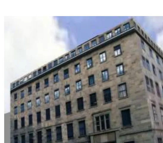
combining photo realistic with pure synthetic approaches. For this issue an efficient rule of thumb is repeating a small and high quality texture in arbitrary vertical and horizontal direction. The texture image file even can be a pixel which is actually a color map. The impression of having unlimited number of layers with different priorities, gives us the opportunity to generate any kind of complex and historical façade. This aim can be achieved from the behavior of raster based applications.
3.0 RELATED WORKS
Using landmarks in mobile navigation systems could improve way finding approach. In this field enriching way finding instructions by means of local landmarks is a reliable method. Simple instructions are defined like geometric data for street network and shape, color, visibility for a determinate façade as visual attraction parameters. Semantic attraction parameters of outstanding landmarks are defined as cultural and historical aspects, Level of importance and Explicit marks e.g. street signs. By using these definitions and information, landmarks are extracted from dataset and provide POI2. In fact the POI
is a hard coded and predefined data which is geo coded in spatial datasets. [Rau02]
The decision for implementing 3D content into navigation system rose at the end of the nineties after a huge progress in hardware design. First of all, generating 3D model of urban area is necessary which can be achieved by creating wire frames out of filtered point clouds. Nowadays this procedure can be done semi-automatically out of laser data or stereo image pairs and photogrammetric methods like Epipolar match points and so on. High quality and rectified photographs from
geometries are exigent for mapping on the wire frame. For this aim disturbing objects must be removed from shadow less photographs. Finally mapping process can be done [Sch07].
The problems of conventional photogrammetry method are disturbing objects, leaning geometries, shadow, and reflection, time consuming, expensive and heavy models, which make it unfit for the intention of navigation system devices. Another project for 3D navigation system
purpose on smart phones, is M-LOMA3[Nur] . This application which is programmed by C++, can be installed on smart phones for running VRML file. The visible part of the model can be rendered on the screen. Moreover lightweight geometry is sued for modeling. In this issue VRML parsing is the first step in implementation process for just visible area on the screen. Texture processing for different LODs comes afterwards which are created and stored separately. In the next step the visibility calculations Based on PVS4 algorithm is done. Then visibility list encoding can be followed by geometry files packaging and compressing them in binary format.
Our concept is combing and extending the solutions. As to show the concept enables the creation of high quality and easy to describe façades for each object with respect to low memory and storage requirements.
4.0 CONCEPT OF SYNTHETIC TEXTURES AND PULSES FUNCTIONS
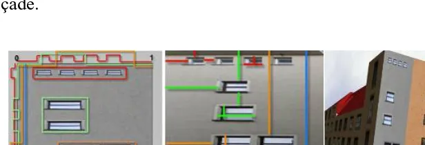
Each building consists of polygons and for each polygon there are some pulse functions in x and y axes which controls the process of texture generation. Pulse function can be easily defined with the logical values. In the intersection of X and Y axes, TRUE means insert and FALSE means not to insert the texture. In order to increase the flexibility, the number of layers of textures and pulse functions are unlimited and each of them has its own priority in respect to others. In the process of creating database for synthetic texturing method, we have to define lots of fields like number of façades which are generating an identical building, texture file name, file path; pulse functions and their related parameters and so on. In MoNa3D we have defined an XML schema for this issue and in this paper we also
3
Mobile LOcation Aware Messaging Application
applied the same schema [Bau08]. Furthermore, we created a user friend interface by means of JavaScript and ActiveX objects of Microsoft windows which can receive the parameters and generates XML files fitting to this schema. The distances between similar textures in horizontal and vertical direction are computed semi automatically in respect to the real geometry for pulse functions by using this program. The number of the layers for each façade can be defied by operators in respect to the requested quality or number of different and sparse textures. In figure 2 five layers are generating the façade.
5.0 SYNTHETIC TEXTURING
5.1 Identifying and describing the texture
We can extract texture heuristically according to the form of the façade. Normally it is possible to find a section on every building façade which is repeating exactly with the same size, form and shape.
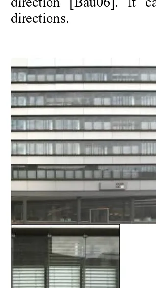
This part should repeat in horizontal or vertical direction with the same distance and often equal size. It depends on the taste of operator and there is no strict rule and automatic method for selecting texture. It can be a vertical slice which is repeating horizontally or horizontal slice which is repeating vertically with a distance equal to zero. Texture of the wall can be stretched in vertical direction or horizontal direction [Bau06]. It can also be repeated as figure 3 in both directions.
5.2 Cropping and rectifying
After deciding which part can be extracted as our texture we have to follow cropping and rectifying procedure. For instance in the figure 3 the texture is illustrated in right part of the picture. In many cases we need rectangle texture, after cropping, rectifying is necessary so that we can remove single point perspective effect of the camera. It is possible to crop and rectify the façade of the building and then crop the selected texture which is as perpendicular as possible to the exposure angle in order to avoid leaning problems. In figure3 we cropped the texture from picture of the rectified and cropped façade from left image of figure 3.
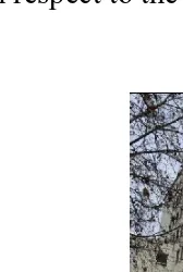
5.3 Removing disturbing objects
5.4 Radiometric adjustment and texture size settings
In order to increase the quality of the model we also need to do some additional exposure settings, radiometric adjustments, color settings, contrast settings and also texture size settings. The texture size is an important issue for generating output image file for different applications. Our Java program is generating a square image file according to our Pulse Function. It is possible to change the size of output image file in java program for each façade even to any shape. In order to have a simple and user friend java program, the size of output image file is defined as a fixed size (256*256 for popular mobile navigation systems and 512*512 for our test in computer
screen and VRML2 environment) in respect to utilized hardware and software.
5.5 Generating the facade semi automatically
In order to generate the façade semi automatically we can follow two different issues. In case that we know/don’t know the geometry of the selected texture in respect to the façade. Both cases depend on the form of textures and taste of the operator for choosing texture. In the following examples we will illustrated these aspects in detail.
In fact the texture which is generated in figure 4 is repeated exactly 25 times in horizontal direction. The distance between them are equal to zero. The out put image file is created without having knowledge of any parameters about the selected texture in respect to the façade.
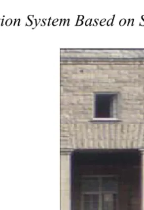
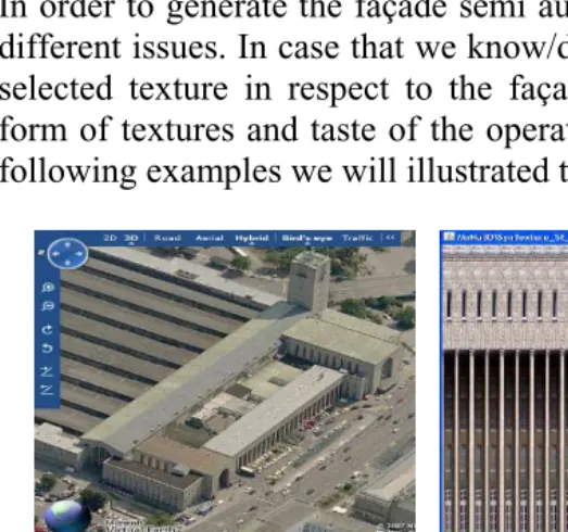
In the next example in order to measure the parameters of texture in respect to the façade, we need to rectify and resize the picture of
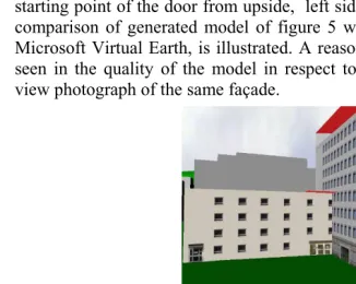
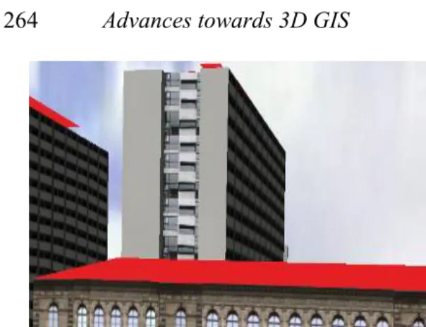
façade without minding quality and completeness like left image of figure 6. This image is rectified and resized form of façade which can be seen in right image of this figure. Lets assume that window is our texture, now we can use different applications like photoshop to measure the parameters like size of the window, starting point from left side, from upside, vertical and horizontal distance between them, starting point of the door from upside, left side and so on. In figure7 comparison of generated model of figure 5 with bird view option of Microsoft Virtual Earth, is illustrated. A reasonable difference can be seen in the quality of the model in respect to low resolution of bird view photograph of the same façade.
5.6 Generating the facade semi automatically
5.7 Mapping the output image file on the geometry
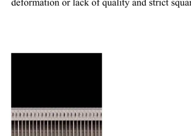
In our task for the process of mapping output file on the geometry, we defined the output image file of Pulse Function as a square shape. We noticed that if the height of building is less than half of the width of the building or width of the building is less than half of the height of the building, we will face with deformation and lack of quality in the process of mapping square output image file on rectangle geometry. In order to deal with this problem we can generate texture or image for the geometry in a part of output image file and use that section for mapping and stretching on the geometry (figure 9). In addition to
above method we can also use different resolutions and shapes or transparent in our Java program to deal with the problem of deformation or lack of quality and strict square shape.
6. TEST ENVIRONMENT
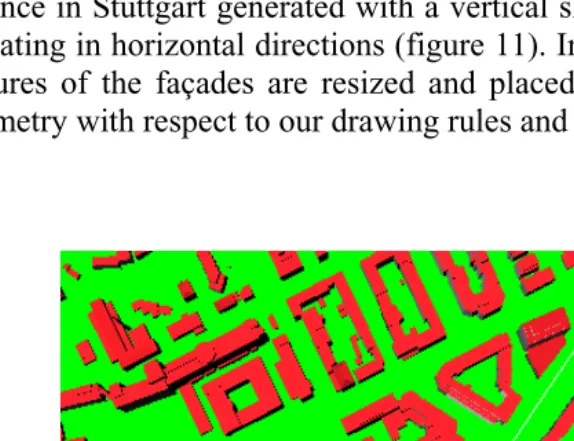
25 buildings where modeled from University of Applied Science to the main train station in Stuttgart and represented in VRML. This path is illustrated in figure 10 with a white line as a shortest path. The wall of some of models is generated with just one pixel or on color map which is repeated in vertical and horizontal directions. Many of other historical buildings like building 1 of the University of Applied Science in Stuttgart generated with a vertical slice of texture which is repeating in horizontal directions (figure 11). In some of buildings the pictures of the façades are resized and placed or mapped on related geometry with respect to our drawing rules and level of details.
7. CONCLUSIONS
REFERENCES
[Coo07]: Volker Coors, Alexander Zipf (2007): MONA 3D -- MOBILE NAVIGATION USING 3D CITY MODELS
[Rau02]: Martin Raubal, Stephan Winter (2002): Enriching Wayfinding Instructions with Local Landmarks - Institute for Geoinformatics, University of Münster, [email protected] -Vienna University of Technology, Austria
[Sch07]: M. Schulze-Horsel: 3D LANDMARKS – GENERATION, CHARACTERISTICS AND APPLICATIONS/ CyberCity AG, In der Luberzen 3, CH-8902 Urdorf, Switzerland - [email protected]
[Nur]:Antti Nurminen, Juha Tuominen: Mobile LOcation-aware Messaging Application -Helsinki University of Technology Industrial Information Technology Laboratory-P.O. Box 9204, 02015 HUT, Finland-MSc [email protected] , PhD [email protected]
[Par01]: Yoav I H Parish, Pascal Müller: Procedural Modeling of Cities, [email protected], [email protected] Switzerland