Scholarship@Western
Scholarship@Western
Electronic Thesis and Dissertation Repository
9-23-2011 12:00 AM
Advanced Islanded-Mode Control of Microgrids
Advanced Islanded-Mode Control of Microgrids
Mohammad Bagher Delghavi
The University of Western Ontario
Supervisor
Dr. Amirnaser Yazdani
The University of Western Ontario
Graduate Program in Electrical and Computer Engineering
A thesis submitted in partial fulfillment of the requirements for the degree in Doctor of Philosophy
© Mohammad Bagher Delghavi 2011
Follow this and additional works at: https://ir.lib.uwo.ca/etd
Part of the Electrical and Computer Engineering Commons
Recommended Citation Recommended Citation
Delghavi, Mohammad Bagher, "Advanced Islanded-Mode Control of Microgrids" (2011). Electronic Thesis and Dissertation Repository. 297.
https://ir.lib.uwo.ca/etd/297
This Dissertation/Thesis is brought to you for free and open access by Scholarship@Western. It has been accepted for inclusion in Electronic Thesis and Dissertation Repository by an authorized administrator of
ADVANCED ISLANDED-MODE CONTROL OF MICROGRIDS
(Spine title: Plib)
(Thesis format: Monograph)
by
Mohammad Bagher Delghavi
Graduate Program in Electrical and Computer Engineering
A thesis submitted in partial fulfillment
of the requirements for the degree of
Doctor of Philosophy
The School of Graduate and Postdoctoral Studies
The University of Western Ontario
London, Ontario, Canada
c
School of Graduate and Postdoctoral Studies
CERTIFICATE OF EXAMINATION
Supervisor:
. . . . Dr. Amirnaser Yazdani
Joint Supervisor:
. . . .
Supervisory Committee:
. . . .
. . . .
Examiners:
. . . . Dr. Mehrdad Kazerani
. . . . Dr. Sam Asokanthan
. . . . Dr. Ilia Polushin
. . . . Dr. Tarlochan S. Sidhu
The thesis by
Mohammad Bagher Delghavi
entitled:
Advanced Islanded-Mode Control of Microgrids
is accepted in partial fulfillment of the
requirements for the degree of
Doctor of Philosophy
. . . . Date
. . . .
Chair of the Thesis Examination Board
Abstract
This thesis is focused on modeling, control, stability, and power management of
electron-ically interfaced Distributed Energy Resource (DER) units for microgrids. Voltage amplitude
and frequency regulation in an islanded microgrid is one of the main control requirements. To
that end, first a mathematical model is developed for an islanded DER system and then, based
on the developed model, amplitude and frequency control schemes are proposed for (i)
bal-anced and linear loads and (ii) unbalbal-anced and nonlinear loads. The proposed control strategy
for unbalanced and nonlinear loads, utilizes repetitive control scheme to reject the effects of unbalanced and/or distorted load currents. Moreover, a new approach is proposed to maintain the effectiveness of the repetitive control under variable-frequency operational scenarios. The thesis also presents an adaptive feedforward compensation strategy to enhance the stability
and robustness of the droop-controlled microgrids to droop coefficients and network uncer-tainties. The proposed feedforward strategy preserves the steady-state characteristics that the
conventional droop control strategy exhibits and, therefore, does not compromise the
steady-state power shares of the DER systems or the voltage/frequency regulation of the microgrid. Finally, a unified control strategy is proposed to enable islanded and grid-connected operation
of DER systems, with no need to detect the microgrid mode of operation or to switch between
different controllers, simplifying the control of the host microgrid. The effectiveness of the pro-posed control strategies are demonstrated through time-domain simulation studies conducted
in the PSCAD/EMTDC software environment.
Keywords: Adaptive control, Current-Mode Control, Distributed Energy Resource (DER),
Droop, Feedforward, Frequency Regulation, Grid-Connected Mode, Islanded Mode,
Micro-grid, Repetitive Control.
To Navideh and my parents
Acknowledgements
I would like to express my sincere gratitude to Professor Amirnaser Yazdani for his
excel-lent supervision, ideas, and encouragement throughout this research. It was a great honor for
me to pursue my higher education under his supervision.
Also, financial support provided by Professor Amirnaser Yazdani and the University of
Western Ontario is gratefully acknowledged.
Certificate of Examination ii
Abstract iii
Dedication iv
Acknowledgements v
List of Figures x
List of Tables xv
List of Appendices xvi
Abbreviations xvii
Nomenclature xviii
1 Introduction 1
1.1 Statement of Problem and Thesis Objectives . . . 1
1.2 Microgrids: Structure, Components, and Principles of Operation . . . 2
1.2.1 Motivations and Benefits . . . 2
1.2.2 Structure and Components . . . 4
1.2.3 Microgrid Control . . . 6
Overall Control (Supervisory Control) . . . 6
Local Control (DER Control) . . . 7
1.2.4 DER Control . . . 8
Grid-Connected-Mode DER Control . . . 8
Islanded-Mode DER Control . . . 10
1.3 Thesis Contributions . . . 11
1.4 Literature Survey Pertinent to Thesis Contributions . . . 13
2 Islanded-Mode DER Control with Load Effect Compensation 18 2.1 Introduction . . . 18
2.2 Structure of the Islanded DER System . . . 19
2.3 Mathematical Model of the Islanded DER System . . . 20
2.4 Control of the Islanded DER System . . . 23
2.5 Study Cases and Simulation Results . . . 27
2.5.1 Configurable Passive Load . . . 27
2.5.2 Induction Machine Load . . . 32
2.6 Conclusion . . . 34
3 Islanded-Mode DER Control for Distorted Load Currents 35 3.1 Introduction . . . 35
3.2 Structure of the Islanded Network and DER System . . . 36
3.3 Current-Control Scheme . . . 38
3.4 Islanded Network Voltage and Frequency Regulation . . . 42
3.4.1 Amplitude Regulation Scheme . . . 42
3.4.2 Frequency Regulation Scheme . . . 44
3.5 Repetitive-Control-Based Compensator for Amplitude Regulation Scheme . . . 46
3.5.1 Fundamentals . . . 46
3.5.2 Extension to Variable-Frequency Systems . . . 49
3.5.3 Closed-Loop Stability . . . 51
3.6 Study Cases and Simulation Results . . . 52
3.6.1 Response to Output Current Imbalance . . . 53
3.6.2 Response to Output Current Distortion . . . 56
3.7 Extension to Multi-System Networks . . . 59
3.7.1 Power Sharing and Decentralized Frequency Control . . . 59
3.8 Conclusion . . . 65
4 Stability Enhancement in Droop-Controlled Microgrids 66 4.1 Introduction . . . 66
4.2 Structure of the DER System . . . 67
4.3 Basic Control . . . 69
4.3.1 Current-Control Scheme . . . 69
4.3.2 Amplitude Regulation Scheme . . . 69
4.3.3 Frequency Regulation Scheme . . . 70
4.4 Proposed Adaptive Feedforward Compensation . . . 72
4.5 Recursive Least-Square Identification Scheme . . . 77
4.6 Study Cases and Results . . . 79
4.6.1 Case 1: Transition to the Grid-Connected Mode Following Inaccurate Synchronization . . . 81
4.6.2 Case 2: Network Topological Change in the Islanded Mode . . . 84
4.6.3 Case 3: Stepwise Increase in Droop Coefficients . . . 85
4.6.4 Case 4: Change in Load/Network Properties . . . 86
4.7 Conclusion . . . 89
5 Unified DER Control 90 5.1 Introduction . . . 90
5.2 Structure of the DER System . . . 91
5.3 Mathematical Model and Control Schemes . . . 92
5.3.1 Current-Control Scheme . . . 92
5.3.2 Amplitude Regulation Scheme . . . 93
5.3.3 Frequency Regulation Scheme . . . 96
5.3.4 Power Control Scheme . . . 97
Real-Power Control Scheme . . . 98
Reactive-Power Control Scheme . . . 101
5.4 Application Examples . . . 102
5.4.1 PV System . . . 102
5.4.2 Battery Energy Storage System (BESS) . . . 103
5.5 Study Cases and Simulation Results . . . 104
5.5.1 Case 1: Response in the Grid-Connected Mode . . . 106
5.5.2 Case 2: Response in the Islanded Mode . . . 108
5.6 Conclusion . . . 110
6 Summary, Conclusions, and Future Work 111 6.1 Summary and Conclusions . . . 111
6.2 Future Work . . . 112
A Load Model and System Parameters for Chapter 2 114 A.1 Mathematical Model of the Load of Fig. 2.6 . . . 114
A.2 System Parameters . . . 115
B Load and System Parameters for Chapter 3 117 C Load, System, and Asynchronous Machine Parameters for Chapter 4 119 C.1 System Parameters . . . 119
C.2 Asynchronous Machine Parameters . . . 119
C.3 Load and Distribution Line Parameters . . . 121
D Base Values and System Parameters for Chapter 5 123
Bibliography 126
Curriculum Vitae 132
1.1 Schematic diagram of an example microgrid. . . 5
1.2 Schematic diagram of a grid-connected DER system with voltage-mode control of real and reactive powers [10]. . . 9
1.3 Schematic diagram of a grid-connected DER system with current-mode control of real and reactive powers. . . 10
1.4 Schematic diagram of a grid-connected nondispatchable DER system with current-mode control of real and reactive powers. . . 11
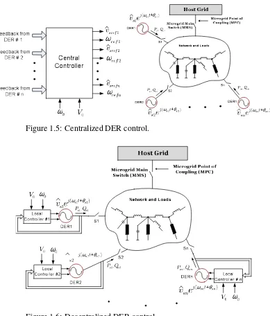
1.5 Centralized DER control. . . 12
1.6 Decentralized DER control. . . 12
2.1 Schematic diagram of a DER system in the islanded mode. . . 20
2.2 Block diagram of the current-control scheme. . . 22
2.3 Block diagram of the voltage-control scheme. . . 25
2.4 Equivalent block diagrams for the closed-loop voltage control scheme. . . 25
2.5 Block diagram of the frequency control loop. . . 27
2.6 Schematic diagram of the configurable passive load. . . 28
2.7 Start-up transient and voltage step responses of the islanded DER system under the no-load condition. . . 29
2.8 Start-up transient and voltage step responses of the islanded DER system under the partially-loaded condition. . . 29
2.9 Start-up transient and voltage step responses of the islanded DER system under the fully-loaded condition. . . 30
2.10 Frequency step responses of the islanded DER system under the no-load con-dition. . . 30
2.11 Frequency step responses of the islanded DER system under the
partially-loaded condition. . . 31
2.12 Frequency step responses of the islanded DER system under a fully-loaded
condition. . . 31
2.13 Response of the islanded DER system to sudden changes in the load
configu-ration. . . 32
2.14 Response of the islanded DER system to sudden switching of the induction
machine load. . . 33
2.15 System behavior in response to a power flow reversal and step changes in the
frequency setpoint. . . 33
3.1 Single-line schematic diagram of the study islanded distribution network. . . . 37
3.2 Schematic diagram of islanded DER system and loads. . . 38
3.3 Block diagram of the current-control scheme of the DER system. . . 41
3.4 Block diagrams of two closed loops equivalent to the current-control scheme
of Fig. 3.3. . . 42
3.5 Block diagram of the amplitude regulation scheme of the DER system. . . 44
3.6 Block diagrams of thed−andq−axis closed loops equivalent to the amplitude regulation scheme of Fig. 3.5. . . 45
3.7 Block diagram of the frequency regulation loop of the DER system. . . 46
3.8 Block diagram of a hypothetical compensator based on the internal model
prin-ciple to reject a periodic disturbance input. . . 47
3.9 Block diagram of the discrete-time realization of the compensator of Fig. 3.8
if the disturbance input frequency is an integer sub-multiple of the sampling
frequency. . . 48
3.10 Block diagram of the proposed repetitive-control-based compensator
incorpo-rated in thed−axis amplitude regulation loop of Fig. 3.6(a). . . 48 3.11 Frequency response of the FIR fractional delay filterQ(z). . . 51
3.12 Overall system response to switching from a balanced load to an unbalanced
load when PI compensators are employed. . . 54
3.14 Overall system response to switching from a balanced load to an unbalanced
load, when repetitive-control-based compensators are employed. . . 55
3.15 Zoomed view of (a) ioabc, (b) vsabc, and (c) PCC voltage, under unbalanced output current and repetitive-control-based compensators. . . 55
3.16 Overall system response to switching from a balanced load to a rectifier load, when PI compensators are employed. . . 57
3.17 Zoomed view of (a)ioabc, (b)vsabc, and (c) PCC voltage, under distorted output current and PI compensators. . . 57
3.18 Overall system response to switching from a balanced load to a rectifier load, when repetitive-control-based compensators are employed. . . 58
3.19 Zoomed view of (a)ioabc, (b)vsabc, and (c) PCC voltage, under distorted output current and repetitive-control-based compensators. . . 58
3.20 Schematic diagram of an example two-system network illustrating the applica-tion of the proposed islanded-mode control strategy in a multi-system microgrid. 60 3.21 Synchronization scheme. . . 62
3.22 Power sharing between the two DER systems; (a) m = me = 1.0 (rad/s)/MW, and (b)m=1.0 (rad/s)/MW,me=2.0 (rad/s)/MW. . . 63
3.23 Zoomed view of (a) ioabc, (b) vsabc, and (c) PCC voltage, under distorted and unbalanced load currents. . . 64
3.24 Overall response of the two-system microgrid. . . 64
4.1 Schematic diagram of the DER system. . . 68
4.2 Block diagram of the current-control scheme of the DER system. . . 70
4.3 Block diagram of the amplitude regulation scheme. . . 71
4.4 Block diagrams of thed−andq−axis closed loops equivalent to the amplitude regulation scheme of Fig. 4.3. . . 71
4.5 Block diagram of the frequency regulation loop. . . 72
4.6 Block diagram of a microgrid embedding a droop-controlled DER system. . . . 73
4.7 Block diagram of the scheme for calculation of feedforward coefficients based
on the estimated parameters. . . 79
4.8 Schematic diagram of the test microgrid. . . 81
4.9 Sample responses of the DER systems to the connection of their host subnet-works to the grid, under the conventional control (Case 1). . . 82
4.10 Sample responses of the DER systems to the connection of their host subnet-works to the grid, under the proposed control (Case 1). . . 83
4.11 Estimated parameters of DER1 under the proposed control (Case 1). . . 83
4.12 Sample responses of the DER systems to the interconnection of the two sub-networks, under the conventional control (Case 2). . . 85
4.13 Sample responses of the DER systems to the interconnection of the two sub-networks, under the proposed control (Case 2). . . 85
4.14 Sample responses of the DER systems to stepwise increase in their droop coef-ficients, under the conventional control (Case 3). . . 87
4.15 Sample responses of the DER systems to stepwise increase in their droop coef-ficients, under the proposed control (Case 3). . . 87
4.16 Sample responses of the DER systems to the introduction of an asynchronous machine to Subnetwork1, under the conventional control (Case 4). . . 88
4.17 Sample responses of the DER systems to the introduction of an asynchronous machine to Subnetwork1, under the proposed control (Case 4). . . 88
5.1 Schematic diagram of a DER system. . . 92
5.2 Block diagram of the amplitude-control scheme. . . 94
5.3 Equivalent block diagrams for the closed amplitude-control loops. . . 96
5.4 Block diagram of the frequency-control loop. . . 97
5.5 Block diagram of the real-power control scheme. . . 99
5.6 Simplified model of a grid-connected DER system. . . 100
5.7 Block diagram of the reactive-power control scheme. . . 102
5.8 Block diagram of the dc-link voltage control scheme for a PV system. . . 104
5.9 Block diagram of the current-control scheme for a battery energy storage system.104
5.12 System responses in the islanded mode (Case 2). . . 109
5.13 Responses of DER systems to a three-phase to ground fault (Case 2). . . 110
B.1 Schematic diagram of the rectifier three-phase load. . . 117
C.1 Schematic diagram of the single-phase network. . . 122
List of Tables
B.1 DER System Circuit and Control Parameters . . . 118
C.1 DER Systems Circuit and Control Parameters . . . 120
C.2 Asynchronous Machine Parameters (Case 4) . . . 120
C.3 Three-Phase Load Parameters . . . 121
C.4 Distribution Line Parameters [1/km] . . . 121
C.5 Single-Phase Load Parameters . . . 122
D.1 Base Values . . . 123
D.2 DER Systems Circuit and Control Parameters [pu] . . . 124
D.3 Load Parameters [pu] . . . 125
D.4 Distribution Line Parameters [1/km] . . . 125
Appendix A Load Model and System Parameters for Chapter 2 . . . 114
Appendix B Load and System Parameters for Chapter 3 . . . 117
Appendix C Load, System, and Asynchronous Machine Parameters for Chapter 4 . . . . 119
Appendix D Base Values and System Parameters for Chapter 5 . . . 123
Abbreviations
A/D Analog to Digital Converter BESS Battery Energy Storage System
CHP Combined Heat and Power
DER Distributed Energy Resource
DNO Distribution Network Operator
FIFO First-In-First-Out
FIR Finite Impulse Response
HV High-Voltage
LC Local Controller
MCC Microgrid Central Controller
MMS Microgrid Main Switch
MO Market Operator
MPC Microgrid Point of Coupling
MPPT Maximum Power-Point Tracking
MV Medium-Voltage
PCC Point of Common Coupling
PI Proportional-Integral
PLL Phase-Locked Loop
PV Photovoltaic
PWM Pulse-Width Modulation
RLS Recursive Least-Square
S/H Sample and Hold
SISO Single-Input-Single-Output
THD Total Harmonic Distortion
VCO Voltage-Controlled Oscillator
VSC Voltage-Sourced Converter
vtabc : VSC ac-side terminal voltage
vsabc : DER system terminal voltage
v′sabc : Transformer voltage iabc : VSC ac-side current
ioabc : DER system output current
iLabc : Load current
vdc : dc-link voltage
Po : Output real power of DER system
Qo : Output reactive power of DER system
Po f : Low-pass filtered measure ofPo
Qo f : Low-pass filtered measure ofQo
PL : Load real power
QL : Load reactive power
iDER : Output current of DER
PDER: Output real power of DER
Cdc : dc-link capacitance
Cf : Capacitance of the DER system LC filter
L : Inductance of the DER system LC filter
R : Parasitic resistance ofL(including on-state resistance of VSC valves)
ω : dq-frame rotational speed ρ : dq-frame reference angle Ts : Sampling period
fs : Sampling and switching frequencies
m : Real power droop coefficient n : Reactive power droop coefficient
Chapter 1
Introduction
1.1
Statement of Problem and Thesis Objectives
A microgrid is defined as a part of an electric power distribution network that embeds an
ap-preciable number of distributed generators and energy storage devices, in addition to regional
loads; it may be disconnected from the rest of the power system, under emergency conditions
or as planned, and operated as an island. A microgrid can be a residential neighborhood, an
in-dustrial or commercial facility, a university campus, a hospital, an off-grid remote community, etc. Microgrids should widely utilize renewable energy resources such as wind, sunlight, and
hydrogen1, to play a significant role in the electric power systems of the future, for cleaner air,
reduced transmission and distribution costs, and enablement of energy efficiency enhancement initiatives. The economical and environmental benefits of microgrids have motivated extensive
research and development efforts towards resolving the technical challenges of this new and fast-growing technology.
The coexistence of multiple of energy resources, which have versatile dynamic properties
and electrical characteristics, has raised concerns over the safety, efficiency, and stability of microgrids. The control and operation of a microgrid is challenging especially in an off-grid scenario where the microgrid is isolated from the main utility grid. This condition is known as
the islanded mode of operation which is the main subject of this thesis.
This thesis concentrates on the islanded-mode control of electronically-interfaced distributed
1Produced through renewable energy resources, for example using solar energy.
generators and energy storage devices, for microgrid applications. Hereafter, a generator, or
an energy storage device, without its interfacing power-electronic converter is referred to as a
Distributed Energy Resource (DER), whereas the same with its power-electronic interface is
referred to as a“DER system”.
The objectives of the thesis are:
• To introduce a continuous-time mathematical model for islanded DER systems and to develop a control strategy for the regulation of the amplitude and frequency of their
ter-minal voltages in the islanded mode of operation, for linear and balanced load conditions.
• To develop a discrete-time mathematical model and a discrete-time control strategy for the regulation of the amplitude and frequency of the terminal voltages of islanded DER
systems which can also mitigate the distortions caused by nonlinear and unbalanced
loads.
• To develop a discrete-time mathematical model and control strategy for droop-controlled microgrids such that dynamic interactions amongst the DER systems, and those amongst
the DER systems and the loads, are tailored and the stability is enhanced.
• To develop a unified control strategy for DER systems that enables them to operate in both islanded and grid-connected modes of operation, with no need for switching
be-tween different control strategies.
1.2
Microgrids: Structure, Components, and Principles of
Operation
1.2.1
Motivations and Benefits
Due to the ever-increasing demand for high-quality and reliable electric power, the concept of
distributed energy resources has attracted widespread attention in recent years [1]. Distributed
energy resources consist of relatively small-scale generation and energy storage devices that are
1.2. Microgrids: Structure, Components,andPrinciples ofOperation 3
consumption, or even export power to the upstream network if their generation surpasses the
local consumption. An upcoming philosophy of operation which is expected to enhance the
utilization of distributed energy resources is known as the microgrid concept [2]- [5]. A
mi-crogrid is referred to as a part of a distribution network embedding multiple distributed energy
resources and regional loads, which can be disconnected from the upstream network under
emergency conditions or as planned. The main benefits of microgrids are high energy efficiency through the application of Combined Heat and Power (CHP), high quality and reliability of the
delivered electric energy, and environmental and economical benefits [2].
The waste heat from the conversion of fuel to electrical power in small generators can be
used by local consumers, through the CHP technology, to raise the efficiency [2].
The issue of the power quality in microgrids is an important issue due to the presence
of an appreciable number of sensitive loads whose performance and lifespan can be adversely
affected by voltage sags, harmonics, and imbalances. In a microgrid, however, most distributed energy resources employ power-electronic converters which can rapidly correct voltage sags,
harmonics, etc., even in the presence of nonlinear and/or unbalanced loads [2]. In addition, the proximity between generation and consumption can improve the reliability of service to
sensitive loads. Reliability is further enhanced by diversification and decentralization of the
supply; thus, loss of one unit can be compensated for by the other units. It should be noted that
the distributed energy resources of a microgrid must have plug-and-play capabilities such that
they can be connected to the microgrid with zero or minimum on-site engineering [3].
The use of clean and renewable energy resources can substantially reduce harmful
emis-sions [2]. The environmental issues have become exceedingly important in developed
coun-tries. For example, the government of Ontario plans to terminate coal-fired generation and
replace it with clean energy technologies; according to a 2005 study prepared for the
govern-ment, the health-related damages of coal could exceed 3 billion dollars a year. In addition,
smaller generators have economical benefits such as shorter construction times and
1.2.2
Structure and Components
The main components of a microgrid are distributed generators (photovoltaic arrays, small
wind turbines, fuel cells, internal combustion engines, microturbines, etc.), distributed
en-ergy storage devices (flywheels, superconductor inductors, supercapacitors, compressed-air
systems, batteries, etc.), and loads. Generators can be classified into two main groups, based
on their interfacing media: (i) generators that consist of direct-coupled conventional rotating
machines (e.g., a synchronous generator driven by a reciprocating engine or an induction
gen-erator driven by a fixed-speed wind turbine), and (ii) electronically interfaced gengen-erators [7].
Distributed energy storage devices are employed to compensate for the power shortage within
the microgrid, mainly in the islanded mode when the generators may not be able to satisfy the
entire load power demand. They also prevent transient instability of the microgrid by
provid-ing power in transients. The instability would occur as many DERs, such as rotatprovid-ing-machine-
rotating-machine-based DERs, fuel-cells, etc., are rather slow in responding to power demand variations; the
transient power shortage in a microgrid can be compensated for by a fast energy storage
de-vice, e.g., a battery that is coupled with the microgrid through a dc/ac converter [8].
Fig. 1.1 shows the schematic diagram of an example microgrid which embeds a
photo-voltaic (PV) system, a variable-speed wind system, and a battery energy storage system. Each
DER is interfaced with its corresponding host bus through a power-electronic converter and
a transformer. The microgrid is interfaced with Bus 1 of the upstream network, at the
Mi-crogrid Point of Coupling (MPC), through the MiMi-crogrid Main Switch (MMS). In turn, Bus
1 is energized from a high-voltage transmission grid, through a substation transformer. The
microgrid has two operating modes: the grid-connected mode and the islanded mode. In the
grid-connected mode, the MMS is closed and the microgrid can exchange energy with the host
grid. In this mode, the DER systems exchange real and reactive powers with the distribution
network, according to the corresponding setpoints; the difference between the aggregate power generated by the DER systems and the power demanded by the local loads is balanced by the
upstream network. The voltages on both sides of the MMS are continuously monitored, and
the switch can be opened to disconnect the microgrid from the grid if a fault strikes the grid.
1.2. Microgrids: Structure, Components,andPrinciples ofOperation 5
Bus 3
Bus 4
Bus 5
Bus 6 Bus 7 Bus 8
Bus 9 Bus 10
Bus 11
Transmission System
Bus 0
Bus 1
Microgrid
Host Grid
Bus 2
Microgrid Main Switch (MMS)
DER1 (Solar)
DER2 (Battery)
DER3 (Wind)
Microgrid Point of Coupling (MPC)
Figure 1.1: Schematic diagram of an example microgrid.
islanded operation is primarily intended to enhance system reliability and service continuity
and, therefore, it is typically unplanned. However, it can also be introduced intentionally, for
maintenance purposes or economical reasons. In some cases, islanded operation is the only
1.2.3
Microgrid Control
Microgrid control can be broadly divided into (i) overall control and (ii) local control. These
controls are described below.
Overall Control (Supervisory Control)
In the grid-connected mode, the microgrid voltage is imposed by the host utility grid. Thus,
the hosted DER systems cannot play any appreciable role in determining the microgrid voltage
magnitude or frequency (although they can locally affect the voltage magnitude through their reactive power or, to a lesser extent, real power contributions). However, they can be controlled
to exchange pre-specified amounts of real and reactive powers with the rest of the microgrid.
This, in turn, enables the control of the real and reactive powers that the microgrid exchanges,
as a black box, with the host grid. In the grid-connected mode, the function of the overall
con-trol is thus to issue the real- and reactive-power commands for the DER systems. The overall
control can calculate the commands based on a variety of criteria, such as market signals and
economy of the microgrid; optimal operation and well being of the microgrid; host grid
con-ditions and requirements; and microgrid internal concon-ditions and requirements. For example,
during hours when the grid electricity is cheap, the overall control may decide to reduce the
power outputs of the gas microturbines and charge the energy storage devices mainly through
the grid power. At the same time, in response to a grid command, it may dispatch the DER
systems in such a way that the microgrid draws reactive power from the host grid, in order to
prevent an overvoltage on the grid side of the MPC.
By contrast, in the islanded mode of operation, the DER systems are mainly controlled to
regulate the microgrid voltage magnitude and frequency, a process that must be fast and
reli-able, and is the function of the local control. In the absence of a connection to the utility grid,
a sustained islanded mode operation also implies that the sum of DER system power outputs
equals the aggregate load power. Although, this is strictly and rapidly ensured by the local
control, the overall control can specify the steady-state DER system output powers, subject
to the constraint mentioned above, in such a way that the microgrid steady-state operation is
magni-1.2. Microgrids: Structure, Components,andPrinciples ofOperation 7
tudes and frequencies of the DER systems (if they have drifted away from their nominal values
due to the islanded-mode operation), for the well being of the loads or safe reconnection of
the microgrid to the host grid once the operating mode is to be switched to the grid-connected
mode. Further, the overall control can shed loads in the islanded mode, depending on load
criticalities, microgrid energy reserves, or other considerations.
The overall control is exercised centrally, through the Microgrid Central Controller (MCC).
It requires a communications network to exchange information with the DER systems and
loads. However, the communication links do not have to be fast or very reliable, since the
over-all control mainly concerns the steady-state operation of the microgrid; its malfunction shover-all
not result in a system collapse, but would lead to the non-optimal operation of the microgrid.
In the technical literature, the overall control is also known as the “supervisory control”,
which may also be augmented with higher levels of control such as Distribution Network
Op-erator (DNO) or Market OpOp-erator (MO) [4] [9].
Local Control (DER Control)
The main function of the local control is to ensure the stability and robustness of the microgrid,
in transients as well as steady states. Thus, the local control ensures that the DER systems
operate in synchronism with the grid, in the grid-connected mode of operation. It also ensures
that, in the islanded mode of operation, the aggregate of the DER system power outputs tracks
the aggregate load power, subject to some dynamics, such that the microgrid voltage magnitude
and frequency are regulated while the DER systems properly share the total load, both in
tran-sient and steady-state regimes. Further, the local control ensures that the DER systems operate
within their limits and are protected against network faults, irrespective of the operating mode.
The local control also receives and enforces the commands that are issued by the overall
control. As mentioned earlier, such commands include setpoints for steady-state output real and
reactive powers of the DER systems; setpoints for steady-state magnitudes and frequencies of
the DER system terminal voltages; and start-up, shut-down, and synchronization commands.
In contrast to the overall control, the local control must be fast and very reliable. Otherwise,
either the microgrid voltage magnitude and frequency undergo unacceptable excursions with
its centralized realization is theoretically feasible, the consensus is that the local control should
be implemented based on decentralized methods. The most notable decentralized method of
local control is the one based on drooped characteristics. One distinct merit of the droop-based
control method is that it grants plug-and-play capability to the DER systems [3]. The method
will be treated in Chapter 4.
It should be pointed out that the local control may also be applied to the loads, for rapid
and continuous power control, or even for load shedding. However, hereafter and throughout
the rest of this thesis, the focus will exclusively be placed on the local control for the DER
systems of a microgrid, and the loads are assumed to be uncontrollable. Hence, hereafter, the
local control is referred more specifically to as the “DER control”.
1.2.4
DER Control
As discussed in Section 1.2.3, two main functions of a DER control are (i) real- and
reactive-power control in the grid-connected mode, and (ii) microgrid voltage and frequency regulation
in the islanded mode. These are discussed next.
Grid-Connected-Mode DER Control
In the grid-connected mode, the magnitude and frequency of the DER system terminal voltages
are imposed by the utility grid. Thus, the control task boils down to the regulation of the real
and reactive powers that the DER systems exchange with the host network. The DER systems
can utilize either the current-mode control method or the voltage-mode control strategy, for the
regulation of their output real and reactive powers.
Fig. 1.2 illustrates a simplified schematic diagram of a voltage-controlled DER system
in which a DER is interfaced with the grid through a Voltage-Sourced Converter (VSC) and
a three-phase inductor, L. Based on the voltage-mode control, the output real and reactive
powers,PoandQo, are controlled by the control of the phase-angle and amplitude of the VSC
ac-side terminal voltagevtabc, relative to those of the host bus voltagevsabc[10]; if the resistance
of the inductor is ignored, the two control variables are almost independent. Thus, each phase
1.2. Microgrids: Structure, Components,andPrinciples ofOperation 9
VSC
and
PWM
Phase-shifter
& scaler
DER System
sabcv
L
oref Q oref P O P O Q Grid Host Bus tabcv
-)
(s
K
P ) (s KQ -sabcv
) (t A ) (t ϕ + dcv
DER
DER i dc C O P O QMesearment
tabcv
*Figure 1.2: Schematic diagram of a grid-connected DER system with voltage-mode control of real and reactive powers [10].
and scaling the amplitude of the corresponding phase ofvsabc [10]. The required phase shift,
ϕ(t), is determined by a feedback loop that processes the error between Po and its respective
setpoint. Similarly, the amplitude scale factor,A(t), is calculated by another feedback loop that
processes the error between theQoand its respective setpoint.
The second method for controlling the real and reactive powers of a grid-connected DER
system is the current-mode control method [10]. In this approach, first the VSC line current is
made controllable by a dedicated scheme and through the control of the VSC terminal voltage.
Then, the real and reactive powers are controlled by the amplitude and phase angle of the
current, relative to those of the host bus voltage. Due to the current regulation provision,
the VSC is protected against overloads and external faults. Other advantages of the
current-mode control include robustness against variations in parameters of the VSC system and the ac
system, superior dynamic performance, and higher control precision [11]. Fig. 1.3 illustrates
the process, which has been extensively discussed in [10].
For the voltage-mode and current-mode control strategies of Figs. 1.2 and 1.3, the DER has
been assumed to be dispatchable, that is, its output real and reactive powers can be controlled
by the setpointsPore f andQore f (which, in turn, are determined by the MCC). By contrast, the
output powers of a nondispatchable DER system are commonly the byproducts of an optimal
Power-VSC R Current-Control Scheme dq i ρ PWM and Gate Drive abc dq
∫
DER System
ω ρ abci
v
sabcdq
m
L ) (s H VCO sdv vsq
PLL abc dq ρ O P O Q Grid Host Bus tabc
v
oref Q oref P -O Q -) (s KP ) (s KQ dref i qref i + dc v DER DER i dc C O PFigure 1.3: Schematic diagram of a grid-connected DER system with current-mode control of real and reactive powers.
Point Tracking (MPPT) mode [12], that is, it extracts the maximum possible power from its
solar panels.
Fig. 1.4 illustrates a simplified schematic diagram of a nondispatchable DER system (e.g.,
a PV system [12]) in which the DER has been modeled by a dc voltage source whose voltage,
vdc, is related to its current, iDER, through a v-i characteristic. As Fig. 1.4 illustrates, the
kernel of the control system is the real- and reactive-power control scheme (of Fig. 1.3) by
which Po andQo can be controlled independently. In the system of Fig. 1.4, the setpoint for
the real power, Pore f, is determined by a feedback control mechanism that regulates vdc at its
corresponding setpoint,vdcre f. The reactive powerQo can be controlled independently by the
setpointQore f. In many applications, Qore f is set at zero, i.e., the VSC system operates at unity
power-factor. Qore f can also be determined by a closed-loop mechanism whose function is to
regulate the voltage magnitude at the host bus [10].
Islanded-Mode DER Control
A microgrid may be islanded due to faults or as planned, for example, for maintenance
pur-poses. In the islanded mode, there is no connection to the host grid. Thus, the DER control
is responsible for frequency regulation. In addition, a voltage regulation strategy is required
to maintain the network voltage. Moreover, the control is also responsible for managing the
1.3. ThesisContributions 11 + VSC R Current-Control Scheme dq i ρ PWM and Gate Drive abc dq
∫
DER System
dc v ω ρ abci
v
sabcdq
m
L ) (s H VCO sdv vsq
PLL abc dq ρ O P O Q Grid Host Bus tabc
v
oref P -O P O Q -) (s KP ) (s KQ dref i qref i N on di sp at ch ab le D E R- vdcref
oref Q ) (s Kdc dc C DER i
Figure 1.4: Schematic diagram of a grid-connected nondispatchable DER system with current-mode control of real and reactive powers.
shared amongst the DER systems of the microgrid. The islanded-mode control can be
exer-cised centrally, as shown in Fig. 1.5. Centralized approaches, however, require remarkable
data transfer capacities and reliable communication links [8] [13] [14]. As such, they may be
suitable for small-scale microgrids in which the DER systems are close together. For DER
systems that are scattered over a large geographical span, decentralized control schemes are
preferable since they do not need data communications; Fig. 1.6 illustrates the concept. This
thesis concentrates on the decentralized DER control, for the islanded mode of operation.
1.3
Thesis Contributions
The main contributions of this thesis can be listed as follows:
• The thesis proposes a voltage and frequency regulation strategy for islanded DER sys-tems. Based on the proposed strategy, the frequency is regulated by controlling the
q-axis component of the terminal voltage of the DER system; a Phase-Locked Loop
(PLL) is employed to provide the frequency information. The proposed method is
fur-ther extended to discrete-time control for a microprocessor-based implementation. The
proposed discrete-time control strategy utilizes a combination of deadbeat and
Feedback from DER # 2
Feedback from DER # n
0
ω V0
1 ref
ωvsref1
Central Controller
Network and Loads 1
1, o oQ P
2 2, o o Q
P P ,onQon
Host Grid S1 DER1 DER2 DERn Microgrid Main Switch (MMS)
Microgrid Point of Coupling (MPC)
) ( 1 j s1t s1 se
v ω +θ
) ( 2 j s2t s2 se
v ω +θ
Sn S2
) ( snt sn
j sne
v ω +θ
Feedback from DER # 1
2 sref v srefn v 2 ref ω refn ω
Figure 1.5: Centralized DER control.
Local Controller #1 0 ω 0 V Local Controller #2 0 ω 0 V Local Controller # n
0 ω 0
V Network and Loads
2 2, o o Q
P P ,onQon
Host Grid S1 DER1 DER2 DERn Microgrid Main Switch (MMS)
Microgrid Point of Coupling (MPC)
) ( 1 j s1t s1 se
v ω +θ
) ( 2 j s2t s2 s ω +θ
Sn S2
) ( snt sn j sn
e
v
ω +θ1 1, o o Q P
Figure 1.6: Decentralized DER control.
distorted load currents. Moreover, a new approach is proposed for maintaining the eff ec-tiveness of the repetitive control under variable-frequency scenarios.
• The thesis further proposes a discrete-time adaptive feedforward compensation strategy that alters the dynamic couplings between a DER system and its host microgrid. The
objective is to enhance the stability and robustness to droop coefficients and network dynamic uncertainties. The proposed compensation strategy preserves the steady-state
1.4. LiteratureSurveyPertinent toThesisContributions 13
not compromise the steady-state power sharing regime of the microgrid or the regulation
of its voltage magnitude and frequency. The proposed compensation is adaptive since
the control is periodically modified according to the DER system steady-state operating
point which, in turn, is estimated through the Recursive Least-Square (RLS) estimation
technique.
• Finally, the thesis proposes a unified control strategy that allows for both the islanded and grid-connected operations of DER systems, with no need for detecting the mode of
operation or switching between different controllers. The proposed unified control strat-egy benefits from both active feedback compensation and droop-based control; it can be
directly adopted for dispatchable DER systems, e.g., battery energy storage systems, or,
alternatively, in nested control loops for non-dispatchable DER systems. Further, it
as-sumes the same power circuit, current-control structure, and synchronization mechanism
as those widely used in the conventional grid-tied power-electronic systems.
1.4
Literature Survey Pertinent to Thesis Contributions
Chapters 2 and 3 of this thesis focus on the control of the amplitude and frequency of the
termi-nal voltage of islanded DER systems; the developments of Chapter 2 are specific to balanced
and linear load conditions, whereas Chapter 3 concentrates on distorted and unbalanced load
conditions.
Reference [15] proposes one of the earliest and most elegant solutions to the islanded-mode
control of DER systems. The control scheme proposed in [15] utilizes anabc-frame
voltage-mode control strategy which is insensitive to load dynamic characteristics and also enables the
incorporation of droop-based power sharing mechanisms. The voltage-mode control, however,
renders the DER system vulnerable to external faults. Other publications in this area have
pri-marily dealt with the issue of control robustness to loads uncertainties. In almost all of them,
the developed models and control strategies are based on pre-specified, balanced, linear, load
circuit configurations [16]- [21]. Therefore, in practice, the proposed methods may not
nec-essarily guarantee the stability, robustness, or performance promised by the assumed models.
is assumed to be known while its parameters are considered uncertain. Moreover, the method
of [17] employs a voltage-mode control approach which calls for additional short-circuit
pro-tection measures. In [18] a voltage-mode control strategy has been proposed for a DER system.
The method is intended for a pre-specified load configuration, but does not take into account
the load topological variations. In an earlier published work, [19], a current-mode control
ap-proach has been employed. However, a parallel RL load has been assumed. Moreover, the
control plant nonlinearities, inherent inter-couplings, and load dynamics are not compensated
for. Consequently, the controller design task relies on linearization and is laborious, and the
system performance depends on the operating point. To accommodate load imbalance, the
control strategy presented in [20] has been extended in [21], based on a positive-/ negative-sequence current-control strategy; again, a pre-specified linear load circuit has been assumed.
In [22] a control strategy has been proposed based on a continuous-time model that includes
load current feedforward, for better stability and performance. However, the control
perfor-mance under unbalanced and nonlinear load conditions is not tested. In [23] a control strategy
has been presented in which a feedforward scheme mitigates the impact of load dynamics on
the control process; the load is assumed to be balanced, but no assumptions are made otherwise
with respect to its circuit configuration or linearity. However, the operation is for a single-unit
islanded system of constant frequency. Moreover, the terminal voltage becomes severely
dis-torted under harmonically-polluted load currents.
Chapter 4 of this thesis concentrates on mitigating the dynamic interactions between the
DER systems in a droop-based controlled microgrid. The droop-based control method is the
most popular technique to ensure power sharing and coordinated voltage and frequency
regu-lation in microgrids [15] [24] [25]. The popularity of the method can be attributed to its ease
of implementation, based merely on local voltage and current information, in addition to the
facts that it enables decentralized control of multiple DER systems, readily accommodates the
grid-connected mode of operation, and enables plug-and-play operation of the DER systems.
The prime issue with respect to the conventional droop-based control is that, it is, in
essence, a steady-state measure that is taken to prevent the DER systems from competing
against each other, for individually imposing the network frequency and voltage; any such
perfor-1.4. LiteratureSurveyPertinent toThesisContributions 15
mance and stability of the droop-based decentralized control highly depend on the droop coeffi -cients, and also on dynamic properties of the network, DER systems, and embedded loads [26].
Even in terms of steady-state performance, the droop-based control is effective the most for highly inductive networks, such as high-voltage transmission networks, but performs rather
poorly when applied to distribution networks [27]. These dependencies, combined with the
fact that the droop coefficients are commonly determined based merely on steady-state crite-ria [15] [24] [25], give rise to the likelihood of inaccurate power-sharing scenarios,
unsatisfac-tory transient performances, or even instabilities, as recently noticed by researchers [26]
[28]-[30].
References [26] and [7] report two studies on dynamic characteristics of islanded
micro-grids that embed droop-controlled electronically-coupled DER systems. In [26] the sensitivity
of the overall system eigenvalues to droop coefficients is shown, whereas [7] places the empha-sis on the controller parameters. Reference [29] proposes a method for improving the transient
power sharing amongst the DER systems. Based on the proposed method, the magnitude and
frequency of each DER system voltage are drooped also versus the derivatives/integrals of the real and reactive output powers. The method proposed in [29] is further advanced in [28] by
making the droop coefficients dependant on the operating point, to mitigate the eigenvalue mi-gration phenomenon and improve the damping of the critical eigenmodes. Based on a slightly
different approach, proposed in [30], the droop coefficients of a DER system are made func-tions of the DER system real and reactive power outputs. In all three references, [26] [29] [30],
it is assumed that a corresponding tie reactor interfaces each DER system with a common ac
bus, which, in turn, is connected to a lumped load. Thus, the common bus voltage is taken as
the reference voltage, and the real and reactive powers that a DER system exchanges with the
network depend only on the magnitude and phase angle of the DER system terminal voltage,
relative to those of the common bus voltage; however, the load is assumed to be an independent
power sink and, as such, exhibits no dynamic interactions with the DER systems. Although
simple, this model, which implicitly assumes a quasi steady-state condition, offers an approxi-mate account of dynamic interactions amongst the DER systems, but obscures the existence of
thus, depend also on the loads. Reciprocally, the loads’ real and reactive powers are functions
of the network voltage and frequency. Consequently, in practice, the aforementioned simplified
model may not guarantee system stability or a satisfactory performance.
On the other hand, due to the diversities in network topologies and equipment, dynamics of
a real-life network are typically governed by complex dynamic models [7] [26] [31], even for
relatively small networks with loads of pre-specified, e.g., RL, configurations. Consequently,
the incorporation of network/load dynamics into the control design process is understandably involved [32], does not promise sufficient generality, and expectedly renders the design prone to case-by-case refinements and compromises the capability for plug-and-play operation.
Chapter 5 of the thesis deals with simplification of the DER control in microgrids.
Micro-grids require cooperation of multiple distributed energy resources (DERs) in both the islanded
mode and the grid-connected mode [2]. This requirement presents the control of DERs, in
particular electronically interfaced DERs, with a major challenge as the two modes of
opera-tion adhere to different and somewhat conflicting dynamic and steady-state characteristics. For example, in the grid-connected mode, the microgrid voltage and frequency are dictated by the
utility grid and, thus, the DERs should act as controllable current sources which exchange
en-ergy with the host network (current-mode control strategy). In the islanded mode of operation,
however, it is the collective responsibility of the DERs to regulate the microgrid voltage and
frequency – a goal that can be achieved most effectively and conveniently if the DERs act as controllable voltage sources (voltage-mode control strategy) [15]. Therefore, researchers have
indicated the need for two distinct sets of controllers, one for the grid-connected mode and the
other one for the islanded mode. This approach, in turn, calls for a fast islanding detection
strategy that detects the microgrid prevailing mode of operation and islanding instant, in order
to activate the corresponding set of controllers [32]- [36].
The main issue associated with the aforementioned two-controller approach is that it makes
the microgrid performance heavily reliant on the speed and accuracy of the islanding detection
process, especially in transient regimes. To the authors’ best of knowledge, there still exists
no conclusive islanding detection method, and the research in this area continues. Having the
knowledge of microgrid operating mode and moment of islanding should not be a pre-requisite
1.4. LiteratureSurveyPertinent toThesisContributions 17
level where reliability does not have to be high. Further, there already exists a great deal of
experience, well-established circuit configurations, and control algorithms for grid-connected
power-electronic interface systems [10]. Hence, from product development and manufacturing
standpoints, it is highly desirable that DERs employ the same circuit configurations, feedback
signals, and transducers also for the off-grid operation.
Reference [15] has shown that the conventionalP−ωdroop-based control is also effective for (real) power output control in the grid-connected mode. The shortcoming of this approach,
however, is that the dynamics of the power control process are fixed by the droop coefficient (which is chosen for proper power sharing in the islanded mode, based on a steady-state
cri-terion [15]) and, consequently, cannot be tailored. Moreover, the proposed control method is
based on the voltage-mode control strategy and thus vulnerable to output shorts and network
faults. Reference [16] proposes a unified control method based on the current-mode control
strategy. To be able to tailor the dynamics, however, the proposed method assumes a
Islanded-Mode DER Control with Load
E
ff
ect Compensation
2.1
Introduction
As illustrated by Figs. 1.5 and 1.6, a DER control task requires rapid and faithful regulation
of the magnitude and frequency of the DER system terminal voltage. The main difficulty, however, is the impact of the load current on the control performance. This chapter proposes a
voltage and frequency regulation strategy that mitigates the load impact. The method will be
extended in Chapter 3 to include nonlinear and unbalanced loads.
The proposed control employs a feedforward compensation strategy to mitigate the impact
of nonlinearities, to eliminate the inter-couplings, and to compensate for the load dynamics.
Therefore, the load dynamics are masked and the system performance is made, to a great
extent, independent of the load type. Thus, the closed-loop system possesses very similar
dynamic properties under no-load and loaded conditions. In addition, the control plant turns out
to be linear, in turn, permitting utilization of classical control design methods and optimization
of the control loops for a stable operation and satisfactory performance over a wide range of
operating points.
The proposed control strategy takes advantage of a PLL and thus avoids the use of an
exter-nal frequency synthesizer. Furthermore, under the proposed control strategy, the islanded DER
system possesses black-start capability and is robust against load switching incidents. Another
2.2. Structure of theIslandedDER System 19
merit of the proposed control is that it allows the DER system to preserve the construction and
control architecture that are established and optimized for grid-connected power-electronic
systems; these include six-pulse pulse-width modulated VSCs, three-phase ac filters,
current-mode control schemes, synchronousdqreference frames, and PLLs.
The chapter details the mathematical modeling and control design methodology, and
demon-strates the effectiveness of the proposed method through simulation studies conducted on a detailed switched model of the overall system, in the PSCAD/EMTDC environment.
2.2
Structure of the Islanded DER System
Fig. 2.1 illustrates a simplified schematic diagram of a DER system, consisting of a
current-controlled VSC and a three-phase LC filter, that supplies an isolated distribution network; an
aggregate of the network loads as viewed from the DER system terminals is labeled as the
“effective load” and is referred to as the “load” throughout this chapter. LandCf represent the
inductance and capacitance of the filter. Rmodels the ohmic loss of the filter inductor and also
includes the effect of the on-state resistance of the VSC valves. The VSC dc side is parallelled with the dc-link capacitorCdcand a voltage source. The voltage source models the effect of a
dispatchable energy storage device, e.g., a battery, which is coupled with the VSC from the dc
side.
Fig. 2.1 illustrates that the DER system is controlled in a rotatingdqreference frame whose
daxis makes an angleρagainst the stationaryαaxis. ρis obtained from a PLL which
consti-tutes an essential part of a modern DER system. The PLL also providesω, i.e., the frequency of
vsabc. In the grid-connected mode of operation,vsabc is dictated by the grid in which caseρand
ωrepresent the phase-angle of the host bus voltage and power system frequency, respectively.
In the islanded mode, however, the switchS is open and the DER system of Fig. 2.1 solely
supplies the load. Thus, the control objective is to regulate the amplitude and frequency of the
host-bus/load voltage, i.e., vsabc. Ideally, this should be accomplished in a stable manner and
+
VSC
R
+
abc
Current Control Scheme
dq
i
ρ dq ρ PWM and Gate Drive abc dq abc dq ρ∫
DER System
tabcv
dcv
ω
ρ abci
Labci
sabcv
dqm
L
) (s H VCO sdv
v
sqPLL
f
C
6
Voltage/Frequency
Control Scheme
i
qrefdref
i
sdrefv
refω
ω
v
sdqω
ρ Effective load oabc
i
odqi
S odqi
Grid Host Bus oP
oQ
dcC
Figure 2.1: Schematic diagram of a DER system in the islanded mode.
2.3
Mathematical Model of the Islanded DER System
With reference to Fig. 2.1, dynamics of the host-bus/load voltage are described by the space-phasor equation Cf d dt − →v s = − →
i −→−io , (2.1)
where each space phasor is defined by the generic equation→−f(t)=(2/3)(fa(t)ej0+ fb(t)ej2π/3+
fc(t)ej4π/3) in which fa(t), fb(t), and fc(t) constitute a three-phase signal or (current/voltage)
waveform. Replacing each→−f(t) (i.e.,→−vs,→−i, and→−io) with (fd(t)+ j fq(t))ejρ(t) in (2.1), one
derives thedq-frame equivalent of (2.1) as
Cf
d
dt[(vsd+ jvsq)e
jρ]= (i
d+ jiq)ejρ−(iod+ jioq)ejρ, (2.2)
whereρ(t) is thedq-frame angle. Equation (2.2) can be simplified and split into
Cf
dvsd
dt =(Cfω)vsq+id−iod (2.3)
Cf
dvsq
2.3. MathematicalModel of theIslandedDER System 21
where
dρ
dt = ω(t) (2.5)
is the output of the PLL.
As shown in Fig. 2.1, the PLL processesvsqthrough the filterH(s) and determinesωin such
a way thatvsqis forced to zero [37]. In the grid-connected mode of operationvsabcis dictated
by the grid. This indicates that the real and reactive power that the DER system delivers to the
distribution network are controlled byid andiq, respectively. In the grid-connected mode, in a
steady state,ωbecomes equal toω0, i.e., the power system angular frequency, whilevsqsettles
at zero. In order for that to happen, H(s) must possess at least one pole at s =0. The PLL is described by
Ω(s)= H(s)Vsq(s), (2.6)
which holds also for the islanded mode wherevsabcis not imposed by the grid, but is a variable
based on (2.1).
As mentioned in the previous section, the electronic interface of the DER system employs
a current-controlled VSC. Thus, the current componentsid andiqare independently controlled
through their respective reference commands, based on [38]
Id(s)=Gi(s)Idre f(s)=
1 τis+1
Idre f(s) (2.7)
Iq(s)=Gi(s)Iqre f(s)=
1 τis+1
Iqre f(s), (2.8)
where the time-constant τi is a design choice. The current control is implemented based on
the block diagram of Fig. 2.2 in which the compensator Ki(s) is Proportional-Integral (PI)
filter. Fig. 2.2 shows thatωis included in the current-control process as a feedforward term to
decouple the control ofid andiq.
In the islanded mode of operation, the DER system output current is equal to the load
d
m
qm
di
qi
-d-axis compensator
q-axis compensator dref
i
Decoupling feed-forward -sdv
sqv
qrefi
L
*
*
ω
L
/
2
v
dc/
)
(s
K
i)
(s
K
iFigure 2.2: Block diagram of the current-control scheme.
of the following nonlinear, time-variant, dynamic system whose inputs arevsdandvsq:
iod
ioq = iLd
iLq =
g1(x1,x2, ...,xn,vsd,vsq,t, ω)
g2(x1,x2, ...,xn,vsd,vsq,t, ω)
, (2.9)
d dt x1 x2 . . . xn =
f1(x1,x2, ...,xn,vsd,vsq,t, ω)
f2(x1,x2, ...,xn,vsd,vsq,t, ω)
. . .
fn(x1,x2, ...,xn,vsd,vsq,t, ω) , (2.10)
where x1(t), ..., xn(t) signify the state variables of the load; f1(.), ..., fn(.), g1(.), andg2(.) are
2.4. Control of theIslandedDER System 23
Equations (2.3) through (2.10) constitute a mathematical model for the islanded system of
Fig. 2.1.
2.4
Control of the Islanded DER System
In the islanded mode, the control of the DER system involves regulation of the host bus
line-to-neutral voltage magnitude, i.e.,bvs= √
v2
sd+v2sq, and the frequencyω. As explained in Section
2.3,vsqsettles at zero in a steady state. Therefore, the regulation of the voltage magnitude boils
down to that ofvsd. On the other hand, based on (2.6), the frequency can be controlled by vsq.
However, control ofvsdandvsqis not a straightforward task. The reasons are (i) based on (2.3)
through (2.10), the open-loop control plant (with idre f andiqre f as the inputs, and vsd andvsq
as the outputs) is nonlinear; (ii) based on (2.3) and (2.4), dynamics ofvsdandvsq are coupled;
(iii) as (2.9) and (2.10) indicate,iod andioq are functions of both vsd andvsq, most likely, with
uncertain and time-varying parameters; and (iv) dynamics of the load are, in general, highly
inter-coupled, of a high dynamic order, and nonlinear, even for a fairly simple linear load; an
example of this is presented in Appendix A.
Fig. 2.3 illustrates a control scheme, capable of largely overcoming the foregoing issues,
in which the filters Kv(s) are the compensators for the d- andq-axis control loops. Fig. 2.3
shows that feedforward signals are utilized to eliminate the coupling betweenvsdandvsq. The
decoupling mechanism employed here is similar to that used to decoupleidandiqin the
current-control scheme of Fig. 2.2. The current-control scheme of Fig. 2.3 enables independent current-control ofvsd
and vsq, respectively, by idre f and iqre f. Fig. 2.3 also shows that measures of iod and ioq are
included in the control process as two other feedforward signals, to mitigate the impact of
the load dynamics on vsd and vsq. Hence, the compensated system behaves under all load
conditions in approximately the same way as the uncompensated system would behave under
a no-load condition. The reason for the effectiveness of the control scheme of Fig. 2.3 can be understood based on the following discussions.
As Fig. 2.3 shows, one has
idre f =ud−(Cfω)vsq+iod (2.11)
whereud anduqare two dummy control inputs. Substituting foridre f andiqre f, from (2.11) and
(2.12), in (2.7) and (2.8), one obtains
Id =Gi(s)Ud−CfGi(s)£{ωvsq}+Gi(s)Iod (2.13)
Iq =Gi(s)Uq+CfGi(s)£{ωvsd}+Gi(s)Ioq, (2.14)
where £{.}denote the Laplace transform operator. It then follows from applying Laplace trans-form to both sides of (2.3) and (2.4), and substituting forId(s) andIq(s) from (2.13) and (2.14),
in the resultants, that
CfsVsd =Gi(s)Ud+|C f[1−Gi(s)]£{ω{zvsq } −[1−Gi(s)]Iod} transient terms
(2.15)
CfsVsq=Gi(s)Uq−| Cf[1−Gi(s)]£{ω{zvsd } −[1−Gi(s)]Ioq} transient terms
. (2.16)
It is then noted that the transfer functionGi(s)= 1/(τis+1) has a unity dc gain, and therefore
[1−Gi(s)]= τis/(τis+1) has a zero dc gain. Hence, ifτi is adequately small, those terms of
(2.15) and (2.16) which are labeled as “transient terms” assume negligible values, and (2.15)
and (2.16) can be approximated as
Vsd(s)
Ud(s) ≈
Gi(s)
1 Cfs
(2.17)
Vsq(s)
Uq(s)
≈Gi(s)
1 Cfs
. (2.18)
Equations (2.17) and (2.18) indicate that vsd and vsq can be independently controlled by,
re-spectively, ud and uq. This alternatively means that the control scheme of Fig. 2.3 divides
the overall voltage control plant, effectively, into two independent Single-Input-Single-Output (SISO) plants of Fig. 2.4. To design Kv(s), one notes that each loop in Fig. 2.4 includes an
integral term, i.e., a pole at s = 0, and a real pole at s = −p = −1/τi. For such a plant, a
PI compensator can ensure a stable fast response and zero steady-state error, if the following
2.4. Control of theIslandedDER System 25 dref
i
qrefi
sdv
sqv
-d-axis compensator
q-axis compensator
sdref
v
qe
de
qu
du
Decoupling feed-forward -odi
oqi
sqrefv
fC
fC
*
*
ω
)
(s
K
v)
(s
K
vFigure 2.3: Block diagram of the voltage control scheme.
s Cf 1 sd
v
sqv
q e de
ud -s Cf 1 q u -sdrefv
sqref
v
)
(
s
G
i)
(
s
G
i)
(s
K
v)
(s
K
vFigure 2.4: Equivalent block diagrams for the closed-loop voltage control scheme.
Let
Kv(s)=k
s+z
s , (2.19)
wherekand−zare the compensator gain and zero, respectively. Then, the open-loop gain is
ℓ(s)= k τiCf
(s+z s+ p)
1
s2 . (2.20)