Port Decoupling vs Array Elements Decoupling for Tx/Rx System
at 7-Tesla Magnetic Resonance Imaging
Ashraf Abuelhaija1, *, Sanaa Salama2, and Tarik Baldawi3
Abstract—Symmetrically excited meandered microstrip line RF coil elements are widely used in multichannel approaches; i.e., being integrated in ultra-high field magnetic resonance imaging (MRI) systems (i.e., 7-Tesla and higher). These elements have demonstrated strong magnetic field in deep areas through the object under imaging. Designing a radio frequency (RF) coil array that employs these elements without decoupling networks might cause non-optimized driving performance of coil array which in turn result in non-clear image. In this paper, two different methods of decoupling are studied: port decoupling and array elements decoupling. In the first one, the coil elements are designed at Larmor frequency (297.3 MHz), while in the other one, the coil elements are designed at higher frequencies but matched at Larmor frequency. Port decoupling does not always mean element decoupling. Conventional decoupling methods, such as single capacitor or inductor, face challenges to realize the coil element decoupling for meandered microstrip arrays. An optimized reactive (T-shaped) network is needed in order to achieve element decoupling which in turn prevents distortion of the EM field. All simulation results have been obtained using the CST time domain solver (CST AG, Darmstadt, Germany).
1. INTRODUCTION
MRI scanners with several magnetic field strengths and different shapes have proved its success in medical diagnosis. In addition to imaging, vendors are investigating the potential of MRI to be used in radiation therapy. Recently, there have been massive research studies on ultra-high magnetic field strength MRI scanners due to their promising results which were obtained in terms of higher SNR and better image quality [1–3].
The challenge of using ultra-high field scanners is that the RF power required for excitation is higher than that for lower field scanners [2, 4]. Increasing RF power level will increase the electric field created by the RF coil in addition to the magnetic field. This electric field will deposit in human body tissue and generates undesirable heating [5]. In general, specific absorption ratio (SAR) is usually high wherever a high B1 field exists. For MRI safety reasons, human body tissues have to be protected from overheating. This can be done by SAR monitoring during an MRI examination in order to avoid undesired levels of SAR [6].
Researchers have proposed several approaches in order to address aforementioned problems which appear when using ultra-high magnetic field. The famous one is the multi-channel parallel RF transmission approach. Static RF shimming is considered as the simplest technique employing this approach [7, 8]. Sensitivity encoding (SENSE) technique is more complicated, where each transmit element uses a different pulses profile in addition to the variation in amplitude and phase during transmission [9, 10]. The most recent, inexpensive, and uncomplicated technique is Time Interleaved
Received 12 September 2019, Accepted 23 December 2019, Scheduled 9 January 2020
* Corresponding author: Ashraf Abuelhaija (a [email protected]).
Acquisition of Modes (TIAMO) [11]. In order to apply multichannel approaches, researchers have developed different RF coil elements such as loops [12–15], ceramic resonators [16], microstrip transmission line elements [17–20], and radiative elements [21–23]. An optimal utilization of multi-channel approach together with RF coil elements is to drive each multi-channel independently. Thus, homogeneous excitation fields over a region of interest (ROI) can be achieved, and this requires good isolation between the coil elements.
In order to achieve this objective, several decoupling methods have been developed and investigated for different coil elements. In an earlier study of decoupling networks for an MRI phased array, a 2n-port decoupling interface has been used to decouple an n-element phased array [24]. In [25], a solid isolation among elements has been achieved by inserting a robust decoupling network between power amplifiers and transmit array elements. Capacitive and inductive decoupling methods have been developed to decouple the adjacent coil elements [26–28]. A parasitic decoupling elements method [29], in which the working principle is based on induced current elimination (ICE), has been presented as a successful decoupling technique for microstipline and monopole coil array elements [30, 31]. In [32], a good improvement in isolation between two closely dipole elements has been achieved by locating an electromagnetic bandgap (EBG) structure over them. Researchers did not stop their decoupling experiments depending only on parasitic elements or passive networks as aforementioned. They went further to modify the design of an RF power amplifier (RFPA) to behave as a current source, thus presenting very high impedance to the neighbouring coil elements in the transmit array [33]. In this case, a power amplifier (PA) is not matched for maximum power delivered. The second RFPA has been designed to have a unique property of ultra-low output impedance. It has demonstrated its capability to isolate the transmit coil elements for 3 T [34] and 7 T [35]. Accordingly, high isolation between elements as well as maximum power transfer were simultaneously achieved. On the other hand, feedback loops were also considered by research in order to reduce the coupling. For example, Cartesian feedback loops were developed, and their performances were verified for 3 T [36] and 7 T [37] MRI systems. An unconventional Cartesian feedback loop was additionally developed and implemented in [38]. It has been used with a new concept of coil current sensing by using a special combination of power amplifiers and coils [39]. Recently, an active decoupling technique using controllable decoupling design was developed and implemented [40].
In this paper, we try to find a convenient decoupling technique for microstripline elements used in 7 T MRI systems. After that, studying the difference between two decoupling methods, port decoupling and elements decoupling, will be introduced. The work presented in this paper is organized as follows. Section 2 presents the widely used microstripline coils in MRI systems at 7 Tesla and their advantages. Section 3 presents the simulation setup for two coupled meander coils. Section 4 discusses two different methods of decoupling: port decoupling and array elements decoupling. Section 5 discusses the results obtained from both decoupling methods, while the conclusion of these decoupling methods is presented in Section 6.
2. MICROSTRIPLINE ELEMENTS
of the microstrip line [18]. These meanders have demonstrated the penetration characteristic inside the human body and decreased the mutual coupling between the adjacent elements [43]. In [44, 45], the meanders of the coil have been loaded with high-dielectric material in order to reduce the SAR value to ensure the safety aspect of the patient. A comprehensive study on this coil has been done in terms of coil parameters such as resonance frequency, input impedance, and Q-factor [46]. The magnetic field distribution of the 3 proposed microstrip line coils has been demonstrated in [47]. These microstrip line coils have been used to implement several coil arrays in 7 T imaging. In [48], an 8-channel transceiver microstrip array has been implemented to build a head coil, whereas in [49] a head coil has been implemented using 16 channels. Both microstrip arrays have demonstrated a promising performance in terms of B1 homogeneity and SAR efficiency. The utilization of microstrip array did not stop on building head coils only, it has also been upgraded to build a whole body coil for both 8-channel body coil [50] and 32-channel body coil [51, 52]. As a result, their corresponding arrays demonstrated promising results in terms of high image quality.
3. MATERIALS AND COIL ARRAY GEOMETRY
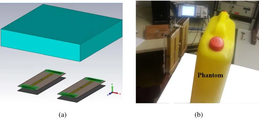
This study focuses on decoupling of two meandered microstrip coils by applying two different decoupling methods: port decoupling and element decoupling. Each coil has two conductors printed on an FR4 substrate (εr = 4.4, tanδ = 0.02). They have dimensions of (250 mm ×100 mm × 0.5 mm). A ground plane is placed 20 mm below the coil and works as reflector. Dielectric substrates (εr = 10, tanδ = 0.0023) have been used to load two meanders at the ends of the conductors. On the top of the meander, the dimensions of the dielectric substrate are (80 mm×20 mm×3.2 mm) whereas the dimensions on the back side are (70 mm×16 mm×3.2 mm). The homogeneous phantom material properties (εr = 45.3, σ = 0.8 S/m) are used to mimic the real human body tissue. The phantom is placed above the coil by a distance of 200 mm and has dimensions of (600 mm×90 mm×370 mm). The effect of different phantom heights on the coil performance is presented in [46].
Figure 1(a) shows the geometry of two coupled meandered microstrip coils with a gap of 100 mm between ground plates, located 200 mm below the homogeneous phantom. The prototype of the coupled coils is shown in Fig. 1(b). A quarter wave length coaxial cable with appropriate characteristic impedance has been used to match the coil input impedance to 50 Ω generator impedance. More geometrical details about the coil and its meanders are presented in [18, 46].
(a) (b)
4. DECOUPLING OF MICROSTRIPLINE ELEMENTS
4.1. Port Decoupling
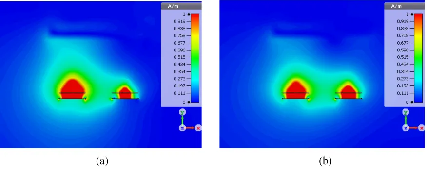
The decoupling network for the coil configuration presented in Fig. 1 has been presented in [53]. It has been designed based on the proposed decoupling network illustrated in [54]. The concept of this network can be summarized by the following: two transmission lines with appropriate characteristic impedanceZo and electrical lengthθ are connected directly to the input terminals of the coupled coils. The admittance seen at the other end of the transmission lines will be purely imaginary, which in case can be cancelled by adding a reactive component between the two transmission lines. Another decoupling network applies a similar concept used in [55]. The main difference was that they used reactive components instead of transmission lines as shown in Fig. 2. These decoupling networks demonstrated promising results in terms of port decoupling of meander coils. Port decoupling method permits the coil elements exciters to work independently from each other but does not isolate the coil elements, i.e., does not eliminate the induced current created due to mutual coupling. Fig. 3(a) shows how the induced current passes through the second element (right), which is terminated by matched load, and creates H-field when the first element (left) is excited by 1 Watt RF signal. Once the port decoupling network in [53] is integrated between the coupled elements, the induced current keeps passing and produces H-field as seen in Fig. 3(b).
jB
jX jX
[Z] T.L
Cm
Port 1 T.L Cm Port 2
Coetzee Network
Matching Network Coupled Coils Matching Network
Figure 2. Coetzee decoupling network.
(a) (b)
Figure 3. Simulated |H| field in a mid-transverse section at 297.3 MHz. (a) Without DN, (b) with DN.
4.2. Element Decoupling
between the coupled elements. The T-shaped decoupling network has been proposed in [56] to decouple closely spaced antennas for MIMO applications. This network has demonstrated a wideband isolation improvement between two strongly coupled antennas.
The resonant frequency of the coil element could be changed by changing the area of the dielectric substrates which covers the meanders in Fig. 1(a) (the green elements). Primarily, these dielectric substrates have been used to increase the electrical length of the coil element to get resonant frequency equal to Larmor frequency for 7 T MRI system (297.3 MHz). Once the area decreases, the electrical length decreases while the resonant frequency increases. In this case, the RF coil element acts as a capacitor at the Larmor frequency as shown in Fig. 4. The input impedance between the coil element terminals (Z2) increases after matching the coil element at 297.3 MHz (see Table 1). This increment in input impedance reduces the induced current (I2) after integrating the T-shaped decoupling network. This decoupling network is composed of two identical networks and a shunt part. The identical networks
0.2 0.5 1.0 2.0 5.0
+j0.2 -j0.2 +j0.5 -j0.5 +j1.0 -j1.0 +j2.0 -j2.0 +j5.0 -j5.0 0.0
Resonance @ 297.3 MHz Resonance @ 307 MHz Resonance @ 335 MHz Frequency = 297.3 MHz Frequency= 297.3 MHz Frequency= 297.3 MHz
Figure 4. Input impedance of meander coil in smith chart representation for different resonant frequencies extended between frequency range from 280 MHz to 320 MHz.
Table 1. Induced currents (I2), mutual impedances (Z21), input impedances between coil element terminals (Z2) andQ-factors for different resonant frequencies.
Resonant Frequency
(MHz)
I2 (A) @ 297.3 MHz Z21 (Ω) @ 297.3 MHz
Mag(Z2) (Ω)
@ 297.3 MHz Q-factor with M.N
& D.N
with M.N & without D.N
with M.N & D.N
with M.N & without D.N
297.3 0.189∠146 ◦
(T-shaped) 0.1327∠−42
◦ 0.267∠67◦
(T-shaped) 4.378∠−48
◦ 5.35 27
307 0.047∠−143 ◦
(T-shaped) 0.1744∠143
◦ 0.0108∠170◦
(T-shaped) 2.76∠134
◦ 29 23.6
335 0.0062∠−129 ◦
(T-shaped) 0.177∠152
◦ 0.0102∠43◦
(T-shaped) 7.4∠138
◦ 65 11.9
335 0.204∠−152 ◦
(Coetzee) 0.177∠152
◦ 26.5∠120◦
(Coetzee) 7.4∠138
jB Rd
jX
Rd
jX [Z]
T.L Cm
Port 1 T.L Cm Port 2
T-shaped Network
Matching Network Matching Network
Coupled Coils
Figure 5. T-shaped decoupling network.
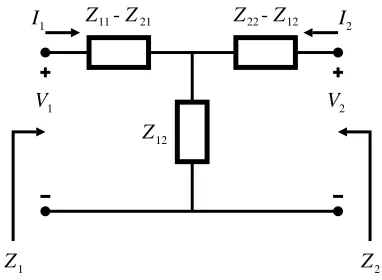
contain a resister and a reactive part while the shunt part consists of a reactive part as seen in Fig. 5. The T-shaped network reduces the mutual impedance (Z21) as well. The mutual impedance (Z21) and input impedance (Z2) expressions haare derived from the two-port network representation shown in Fig. 6. They can be obtained as follows [57]:
Z21 = V2 I1
I2=0
(1)
Z2 = Z22+Z21
I1 I2
(2)
whereI1 is the current passing through the first coil element (left) when it is excited by RF generator, and I2 is the induced current passing through the second coil element (right). Both currents have been calculated using current probes offered in CST. The self-impedance of the second coil element (Z21) can be obtained by:
Z22= V2 I2
I1=0
(3)
Z12
V1 V2
I1 I2
Z1 Z2
Z 11- Z21 Z 22- Z12
Figure 6. Equivalent network for two-coupled
5. RESULTS AND DISCUSSION
Induced currents, mutual impedances, input impedances between coil element terminals, andQ-factors for different resonant frequencies shown in Table 1 have been calculated by using the above mentioned expressions whereas all cases have been matched at Larmor frequency. It is obvious that by increasing the resonant frequency, the input impedance of the coil element increases while the mutual impedance and the induced current by using T-shaped decoupling network decrease. Coetzee decoupling network (Fig. 2), which has demonstrated high port decoupling, has been tested for elements decoupling purposes. The last case in Table 1 summarizes the results obtained by using a Coetzee decoupling network when utilizing RF coil elements designed at 335 MHz resonant frequency and matched at Larmor frequency. In spite of high input impedance obtained between the RF coil elements terminals at 335 MHz, the induced current keeps passing through the second element because the mutual impedance increases and creates magnetic field as shown in Fig. 7. In all cases, both decoupling networks demonstrate high port decoupling as shown in Fig. 8(a), whereas the S-parameters for two-coupled RF coil elements before adding decoupling network are seen in Fig. 8(b). Fig. 9 clarifies how the magnetic fields are created by the induced current in the element disappears gradually by increasing the resonant frequency in comparison with the case seen in Fig. 3.
In order to get clearer view on the improvement ofH-field due to the reduction of induced current, 2D plots of H-field have been obtained in the mid transverse section as seen in Fig. 10. These plots have been made at 10 mm inside the phantom while the height of the phantom is 50 mm above the RF coil elements. This figure demonstrates the behavior of the magnetic field strength for the first three
280 285 290 295 300 305 310 315 320 -60
-50 -40 -30 -20 -10 0
S
(dB) 297.3 MHz307 MHz
335 MHz
335 MHz (Coetzee D.N)
-40 -30 -20 -10 0
S
-parameters (dB)
S S
(a) (b)
Frequency (MHz)
280 285 290 295 300 305 310 315 320
Frequency (MHz)
21
21 11
Figure 8. (a)S21with MN and DN for different resonant coils, (b)S-parameters with MN but without DN for 297.3 MHz resonant coil.
(a) (b)
0 0.2 0.4 0.6 0.8 1 1.2
H
-field (A/m)
297.3 MHz 307 MHz 335 MHz
-150 -100 -50 0 50 100 150 Lateral-axis (mm)
Figure 10. Magnetic field strength, 10 mm inside the phantom at different frequencies.
Tesla/sqrt(Pacc) Tesla/sqrt(Pacc) Tesla/sqrt(Pacc)
(a) (b) (c)
Figure 11. Transmit efficiency at different frequencies: (a) 297.3 MHz, (b) 307 MHz and (c) 335 MHz.
Table 2. Values of T-shaped and Coetzee decoupling networks elements for different resonant frequencies.
Resonant Frequency (MHz)
Decoupling
Network B X R(Ω)
T.L
(electrical length) Cm(pf)
297.3 T-shaped −0.2549 −9.987 25.6 0.42 2.6
307 T-shaped 0.01438 339.78 88.6 0.262 5
335 T-shaped 0.00819 −2.549 60 0.258 8.35
335 Coetzee −0.063 58.28 — 0.21 5.1
(a) (b) (c)
Figure 12. 10 g-based Local SAR at different frequencies: (a) 297.3 MHz, (b) 307 MHz and (c) 335 MHz.
on unwanted region. The last case shows a reduction of transmit field distribution. Fig. 12 shows the 10 g-based Local SAR for the three cases. A significant reduction in the maximum local SAR has been observed for higher resonant frequency elements. The max SAR (10 g) for the first case is 0.40 W/kg. For the second and third cases, the max SARs (10 g) are 0.47 W/kg and 0.088 W/kg, respectively.
6. CONCLUSION
This paper has demonstrated two different array coil decoupling methods: port decoupling and array elements decoupling. For port decoupling, a Coetzee decoupling network and T-shaped decoupling network have demonstrated high port decoupling for any resonant frequency at which the RF coil element has been designed and matched at Larmor frequency. This method can eliminate or even reduce the mutual coupling between two coil ports. In contrast, the induced current can appear within the passive element in the array due to the mutual coupling and distort the EM radiation from the active element. For coil elements decoupling, only the T-shaped decoupling network decouples the coil elements once the RF coil element is designed at a frequency higher (or lower) than the Larmor frequency and matched at Larmor frequency. The element decoupling is preferred since it ensures that no induced current passes through the passive element and maintains the EM field from original coil elements. Port decoupling actually distorts the original EM field.
ACKNOWLEDGMENT
This work has been done at the department of Electrical Engineering, Faculty of Engineering at the Applied Science Private University, Amman, Jordan. The authors would like to thank the university for their strong support to this work.
REFERENCES
1. Yacoub, E., A. Shmuel, J. Pfeuffer, P. F. van de Moortele, G. Adriany, P. Andersen, J. T. Vaughan, H. Merkle, K. Ugurbil, and X. Hu, “Imaging brain function in humans at 7 Tesla,” Magnetic Resonance in Medicine, Vol. 45, No. 4, 588–594, 2001.
2. Vaughan, J. T., M. Garwood, C. M. Collins, W. Liu, L. DelaBarre, G. Adriany, P. Andersen, H. Merkle, R. Goebel, M. B. Smith, and K. Ugurbil, “7 T vs. 4 T: RF power, homogeneity, and signal-to-noise comparison in head images,”Magnetic Resonance in Medicine, Vol. 46, No. 1, 24–30, 2001.
3. Collins, C. M. and M. B. Smith, “Signal-to-noise ratio and absorbed power as functions of main magnetic field strength, and definition of 90◦ RF pulse for the head in the birdcage coil,”Magnetic Resonance in Medicine, Vol. 45, No. 4, 684–691, 2001.
5. Brown, R. W., E. M. Haacke, M. A. Martens, J. L. Patrick, and F. R. Zypman, “A layer model for RF penetration, heating, and screening in NMR,” Journal of Magnetic Resonance Imaging, Vol. 80, No. 2, 225–247, 1988.
6. Wang, Z., J. C. Lin, W. Mao, W. Liu, M. B. Smith, and C. M. Collins, “SAR and temperature: Simulations and comparison to regulatory limits for MRI,”Journal of Magnetic Resonance Imaging, Vol. 26, No. 2, 437–41, 2007.
7. Wang, Z., J. C. Lin, W. Mao, W. Liu, M. B. Smith, and C. M. Collins, “Combination of optimized transmit arrays and some receive array reconstruction methods can yield homogeneous images at very high frequencies,” Magnetic Resonance in Medicine, Vol. 54, No. 6, 1327–1332, 2005.
8. Mao, W., M. B. Smith, and C. M. Collins, “Exploring the limits of RF shimming for high-field MRI of the human head,”Magnetic Resonance in Medicine, Vol. 56, No. 4, 918–922, 2006. 9. Katscher, U., P. B¨ornert, C. Leussler, and J. S. van Den Brink, “Transmit SENSE,” Magnetic
Resonance in Medicine, Vol. 49, No. 1, 144–150, 2003.
10. Grissom, W., C. Y. Yip, Z. Zhang, V. A. Stenger, J. A. Fessler, and D. C. Noll, “Spatial domain method for the design of RF pulses in multicoil parallel excitation,” Magnetic Resonance in Medicine, Vol. 56, No. 3, 620–629, 2006.
11. Orzada, S., S. Maderwald, B. A. Poser, A. K. Bitz, H. H. Quick, and M. E. Ladd, “RF excitation using time interleaved acquisition of modes (TIAMO) to address B1 inhomogeneity in high-field MRI,”Magnetic Resonance in Medicine, Vol. 64, No. 2, 327–333, 2010.
12. Wiggins, G. C., A. Potthast, C. Triantafyllou, C. J. Wiggins, and L. L. Wald, “Eight-channel phased array coil and detunable TEM volume coil for 7 T brain imaging,” Magnetic Resonance in Medicine, Vol. 54, No. 1, 235–240, 2005.
13. Avdievich, N. I., “Transceiver-phased arrays for human brain studies at 7 T,” Applied Magnetic Resonance, Vol. 41, Nos. 2–4, 483–506, 2011.
14. Kraff, O., A. K. Bitz, S. Kruszona, S. Orzada, L. C. Schaefer, J. M. Theysohn, S. Maderwald, M. E. Ladd, and H. H. Quick, “An eight-channel phased array RF coil for spine MR imaging at 7 T,”Investigative Radiology, Vol. 44, No. 11, 734–740, 2009.
15. Salama, S., “Design of a rectangular loop-shape RF coil for 7-Tesla magnetic resonance imaging,”
Microwave Conference (APMC), 1044–1047, 2017.
16. Aussenhofer, S. A. and A. G. Webb, “An eight-channel transmit/receive array of TE01 mode high permittivity ceramic resonators for human imaging at 7 T,”Journal of Magnetic Resonance, Vol. 243, 122–129, 2014.
17. Brunner, D. O., N. De Zanche, J. Froehlich, D. Baumann, and K. Pruessmann, “A symmetrically fed microstrip coil array for 7 T,” Proc. 15th Annu. Meeting ISMRM, 2007.
18. Orzada, S., A. Bahr, and T. Bolz, “A novel 7 T microstrip element using meanders to enhance decoupling,”Proc. 16th Annu. Meeting ISMRM, 2008.
19. Zhang, X., K. Ugurbil, and W. Chen, “Microstrip RF surface coil design for extremely high-field MRI and spectroscopy,” Magnetic Resonance in Medicine, Vol. 46, No. 3, 443–450, 2001.
20. Zhang, X., K. Ugurbil, R. Sainati, and W. Chen, “An inverted-microstrip resonator for human head proton MR imaging at 7 Tesla,” IEEE Transactions on Biomedical Engineering, Vol. 52, No. 3, 495–504, 2005.
21. Raaijmakers, A. J. E., O. Ipek, D. W. Klomp, C. Possanzini, P. R. Harvey, J. J. Lagendijk, and C. A. van Den Berg, “Design of a radiative surface coil array element at 7 T: The single-side adapted dipole antenna,”Magnetic Resonance in Medicine, Vol. 66, No. 5, 1488–1497, 2011. 22. Hong, S. M., J. H. Park, M. K. Woo, Y. B. Kim, and Z. H. Cho, “New design concept of monopole
antenna array for UHF 7 T MRI,” Magnetic Resonance in Medicine, Vol. 71, No. 5, 1944–1952, 2014.
24. Lee, R. F., R. O. Giaquinto, and C. J. Hardy, “Coupling and decoupling theory and its application to the MRI phased array,”Magnetic Resonance in Medicine, Vol. 48, No. 1, 203–213, 2002. 25. Mahmood, Z., B. Gu´erin, E. Adalsteinsson, L. L. Wald, and L. Daniel, “Design of a robust
decoupling matrix for high field parallel transmit arrays,”Proc. Intl. Soc. Mag. Reson. Med., 2014. 26. Jevtic, J., “Ladder networks for capacitive decoupling in phased-array coils,” Proceedings of the
9th Annual Meeting of ISMRM, 2001.
27. Wu, B., X. Zhang, P. Qu, and G. X. Shen, “Design of an inductively decoupled microstrip array at 9.4 T,”Journal of Magnetic Resonance, Vol. 182, No. 1, 126–132, 2006.
28. Salama, S., “Reactive-element based decoupling network for a two-element MRI phased array,”
Journal of King Saud University-Engineering Sciences, 2018.
29. Li, Y., Z. Xie, Y. Pang, D. Vigneron, and X. Zhang, “ICE decoupling technique for RF coil array designs,”Medical Physics, Vol. 38, No. 7, 4086–4093, 2011.
30. Abuelhaija, A., S. Orzada, and K. Solbach, “Parasitic element based decoupling of 7 Tesla MRI coil array,” Antennas and Propagation Conference (LAPC), 2015.
31. Yan, X., X. Zhang, L. Wei, and R. Xue, “Magnetic wall decoupling method for monopole coil array in ultrahigh field MRI: A feasibility test,” Quantitative Imaging in Medicine and Surgery, Vol. 4, No. 2, 79, 2014.
32. Hurshkainen, A. A., T. A. Derzhavskaya, S. B. Glybovski, I. J. Voogt, I. V. Melchakova, C. A. van Den Berg, and A. J. Raaijmakers, “D element decoupling of 7 T dipole body arrays by EBG metasurface structures: Experimental verification,”Journal of Magnetic Resonance, Vol. 269, 87– 96, 2016.
33. Lee, W., E. Boskamp, T. Grist, and K. Kurpad, “Radiofrequency current source (RFCS) drive and decoupling technique for parallel transmit arrays using a high-power metal oxide semiconductor field-effect transistor (MOSFET),” Magnetic Resonance in Medicine, Vol. 62, No. 1, 218–228, 2009.
34. Chu, X., X. Yang, Y. Liu, J. Sabate, and Y. Zhu, “Ultra-low output impedance RF power amplifier for parallel excitation,” Magnetic Resonance in Medicine, Vol. 61, No. 4, 952–961, 2009.
35. Abuelhaija, A. and K. Solbach, “An ultra-low output impedance power amplifier for Tx array in 7-Tesla magnetic resonance imaging,” International Conference on Microwave Science and Technology, 2015.
36. Hoult, D. I., G. Kolansky, D. Kripiakevich, and S. B. King, “The NMR multi-transmit phased array: A Cartesian feedback approach,” Journal of Magnetic Resonance, Vol. 171, No. 1, 64–70, 2004.
37. Abuelhaija, A., K. Solbach, and A. Buck, “Power amplifier for magnetic resonance imaging using unconventional Cartesian feedback loop,” German Microwave Conference (GeMiC), 2015.
38. Abuelhaija, A., “Power amplifier for magnetic resonance imaging using unconventional cartesian feedback loop,” Ph.D thesis, Duisburg-Essen University, Duisburg, 2016.
39. Solbach, K., A. Abuelhaija, and S. Shooshtary, “Near-magnet power amplifier with built-in coil current sensing,”22nd Proc. Intl. Soc. MRM, 2014.
40. Salim, M., A. C. Ozen, M. Bock, and E. Atalar, “Active decoupling of transmit and receive coils for full-duplex MRI,” arXiv preprint arXiv: 1810.10973, 2018.
41. Vaughan, J. T., H. P. Hetherington, J. O. Otu, J. W. Pan, and G. M. Pohost, “High frequency volume coils for clinical NMR imaging and spectroscopy. Magnetic resonance in medicine,”Magnetic Resonance in Medicine, Vol. 32, No. 2, 206–218, 1994.
42. Adriany, G., A. Gozubuyuk, J. Ritter, C. Snyder, P. F. van de Moortele, S. Moeller, J. T. Vaughan, and K. Ugurbil, “A 32 channel lattice transmission line array for parallel MRI,”Proc. 14th Annual Meeting of the ISMRM, 2006.
44. Chen, Z., K. Solbach, D. Erni, and A. Rennings, “Dipole RF element for 7 Tesla magnetic resonance imaging with minimized SAR,”7th European Conference on Antennas and Propagation (EuCAP), 2013.
45. Saleh, G., K. Solbach, A. Rennings, and Z. Chen, “SAR reduction for dipole RF coil element at 7 Tesla by using dielectric overlay,” Loughborough Antennas and Propagation Conference (LAPC 2012), 2012.
46. Abuelhaija, A., K. Solbach, and S. Orzada, “Comprehensive study on coupled meandered microstrip line RF coil elements for 7-Tesla magnetic resonance imaging,” 9th European Conference on
Antennas and Propagation (EuCAP), 2015.
47. Orzada, S., K. Solbach, M. E. Ladd, and A. K. Bitz, “Comparison of three different microstrip transmit elements for use in multichannel Tx/Rx body coils at 7 Tesla,” 22nd Proc. Intl. Soc. MRM, 2014.
48. Orzada, S., O. Kraff, L. C. Sch¨afer, I. Brote, A. Bahr, T. Bolz, S. Maderwald, M. E. Ladd, and A. K. Bitz, “8-channel transmit/receive head coil for 7 T human imaging using intrinsically decoupled strip line elements with meanders,”Proc. Int. Soc. Magn. Reson. Med., 2009.
49. Wu, B., C. Wang, D. A. Kelley, D. Xu, D. B. Vigneron, S. J. Nelson, and X. Zhang, “Shielded microstrip array for 7 T human MR imaging,” IEEE Transactions on Medical Imaging, Vol. 29, No. 1, 179–184, 2010.
50. Orzada, S., A. K. Bitz, S. Johst, M. Gratz, M. N. V¨olker, O. Kraff, A. Abuelhaija, T. M. Fiedler, K. Solbach, and H. H. Quick, “Analysis of an integrated 8-channel Tx/Rx body array for use as a body coil in 7-Tesla MRI,” Frontiers in Physics, Vol. 5, 17, 2017.
51. Orzada, S., A. K. Bitz, O. Kraff, M. Oehmigen, M. Gratz, S. Johst, M. N. V¨olker, S. H. G. Rietsch, M. Fl¨oser, T. Fiedler, and S. Shooshtary, “A 32-channel integrated body coil for 7 Tesla whole-body imaging,”Proceedings of the 24th Annual Meeting of ISMRM, 2016.
52. Orzada, S., K. Solbach, M. Gratz, S. Brunheim, T. M. Fiedler, S. Johst, A. K. Bitz, S. Shooshtary, A. Abuelhaija, M. N. Voelker, and S. H. Rietsch, “A 32-channel parallel transmit system add-on for 7 T MRI,”PloS One, Vol. 14, 9, 2019.
53. Abuelhaija, A., S. Salama, and O. Nashwan, “Decoupling network for Tx/Rx body coil for 7 Tesla MRI,”Turkish Journal of Electrical Engineering and Computer Sciences, Vol. 27, 6, 2019.
54. Chen, S. C., Y. S. Wang, and S. J. Chung, “A decoupling technique for increasing the port isolation between two strongly coupled antennas,”IEEE Transactions on Antennas and Propagation, Vol. 56, No. 12, 3650–3658, 2008.
55. Coetzee, J. C. and Y. Yu, “Closed-form design equations for decoupling networks of small arrays,”
Electronics Letters, Vol. 44, No. 25, 1441–1442, 2008.
56. Li, L., S. Venkatasubramanian, A. Lehtovuori, C. Icheln, M. Heino, and K. Haneda, “T-shaped decoupling network for wideband isolation improvement between two strongly coupled antennas,”
Loughborough Antennas and Propagation Conference (LAPC), 2015.