Optimization Study of Radar Cross Section Reduction by an
Inhomogeneous Collisional Magnetized Plasma
Vahid Foroutan*, 1, Mohammad N. Azarmanesh1, and Gholamreza Foroutan2
Abstract—Recursive convolution FDTD method is employed to study the bistatic radar cross section
(RCS) of a conductive plate covered with an inhomogeneous magnetized plasma shroud. The results of numerical simulations reveal that for a plasma of number density 5×10¹⁷m−3 and collision frequency of 1 GHz, RCS reduction (RCSR) is improved i.e., its maximum reduction, bandwidth, and angular width are enhanced, when a perpendicular magnetic field of intensity B = 0.25 T is applied. However, increase of the magnetic field to 0.4 T leads to a much lower RCSR specially for the backscattered wave. As the collision frequency is increased to 10 GHz, the RCSR is enhanced both in the presence and absence of the magnetic field. However, with further increase of collision frequency to 60 GHz, the RCSR is significantly reduced and the problem is more severe in the backward direction. The resonant absorption is dominant at low to moderate collision frequencies, for magnetic field intensity above 0.1 T, but becomes almost inefficient when the collision frequency is increased to 60 GHz. The RCSR is considerably weakened when the plasma number density is reduced and the effect is prominent for small angles. A plasma inhomogeneity length scale of 5 cm provides the maximum RCSR in the presence of the magnetic field. With increase of the length scale, the maximum RCSR, the corresponding wave frequency, and bandwidth all are reduced. Therefore, it is concluded that a plasma with number density of 5×10¹⁷m−3, collision frequency of 10 GHz, and length scale of 5 cm, with a perpendicular magnetic field of 0.25 T is the best choice for optimum RCSR of a conductive plate.
1. INTRODUCTION
Radar absorbing materials (RAMs) have been widely used to reduce the reflection of radar transmitted waves in stealth technology. But, low absorption bandwidth, significant body weight, and strong reflections in certain directions are a number of limitations of polymeric radar absorbing materials. The collisional plasma due to its wide absorption bandwidth, low weight, and, high absorption rate, is one of the most effective materials for electromagnetic (EM) waves absorption. The plasma based stealth technology has been reported to be applicable to any aircrafts and aerospace vehicles [1]. Two additional unique features of plasma segregate it from the rest of the radar absorbing materials. The first important feature is the switching ability, i.e., which the plasma can be turned off for transmitting the desired signals. The second one is the capability of adjustment of the plasma response via variation of parameters such as the electron density and collision frequency, as well as an application of the external magnetic field, to optimize the absorption characteristic.
The electromagnetic waves attenuation in propagation through a collisional plasma has been known for decades. But, plasma as a strong and broadband absorber was first introduced by Vidmar [2]. He showed that a collisional plasma can strongly absorb the incident EM waves in the frequency range from VHF to X-band, through the energy transfer from electrons to the neutral particles. The laboratory
Received 16 April 2019, Accepted 1 June 2019, Scheduled 14 June 2019 * Corresponding author: Vahid Foroutan ([email protected]).
experiments by Stalder [3] et al. confirmed the Vidmar theory of EM absorption by plasma. The experimental results also showed that a plasma generated through photoionization of noble gases, leads to significant attenuation of microwaves up to 28 dB. Also, the laboratory measurements by Srivastava [4] et al. revealed that the absorption of EM waves in plasma can be greatly enhanced by increasing the electron number density and the plasma layer thickness.
Following the introduction of plasma as EM waves absorbent, a lot of research works have focused on the modeling of microwave interaction with plasma and optimization of plasma parameters to enhance some desired properties. These efforts can be classified into two main groups, known as approximate and exact methods. In the approximate methods, the plasma layer is divided into several sublayers, and the reflection, absorption, and, transmission coefficients are computed for each sublayer, and then the overall coefficients are estimated from these partial coefficients. The propagator matrix method (PMM) [5], and scattering matrix method (SMM) [6] are the most frequently used approximate methods in the study of plasma and EM waves interaction. The most frequently used exact method is finite difference time domain (FDTD) algorithm which was first introduced by Yee [7], and addresses the numerical solutions of the Maxwell equations in the plasma [8–12]. By comparing the approximate and exact methods, Chaudhury et al. concluded that the results obtained by the approximate methods have sufficient accuracy only if the electron density gradient length scale is larger than the free space wavelength [13]. Due to frequency dependence of the plasma permittivity, the standard FDTD cannot be directly used to simulate the propagation of EM waves in the plasma. Several schemes have been proposed to extend the standard FDTD to dispersive media. The recursive convolution FDTD (RC-FDTD), introduced by Luebbers et al., is the first extended model [14–16]. In this method, instead of direct evaluation the convolution integral of the electric field and susceptibility function, the expression at each time step is stored in a variable and, then a recursive summation of this variable in two consecutive time steps results in the main value of the convolution integral. The piecewise linear RC (PLRC) FDTD and trapezoidal RC (TRC) FDTD are two more accurate versions of RC-FDTD in which, the electric field between two steps is approximated by linear and trapezoidal interpolations, respectively, instead of a constant value [17, 18]. The Z transform algorithm is another accurate scheme for modeling of dispersive media [19, 20]. In this approach, the complex formulation of RC-FDTD in the time domain is replaced by a concise formulation in the Z domain. The third dispersive method is called auxiliary differential equation (ADE) method in which the integral relation betweenD and E is converted into a differential equation by using the Fourier theory [21–23].
By application of an external magnetic field, the plasma becomes anisotropic and its permittivity takes tensor form. The presence of magnetic field also changes the reflection, absorption, and transmission coefficients of the plasma. The results obtained by Laroussi and Roth indicated that application of an external magnetic field leads to a strong wave absorption around the cyclotron frequency [24]. By increasing the electron-neutral collision frequency, both the reflection and absorption coefficients are reduced, but the transmission coefficient is increased. Also, an increase in the electron density leads to enhanced absorption and reflection coefficients. Petrin showed that the presence of a magnetic field amplifies the absorption of the waves around electron cyclotron frequency, but further increase of the magnetic field intensity reduces the absorption, while increases the transmission compared to unmagnetized plasma [25]. His results also revealed that the absorption can be enhanced by increasing the collision frequency. For a magnetized plasma, Tang et al., [26] found that increasing the collision frequency in a high-density plasma would increase the wave absorption, but the reverse is true for a low-density plasma. Also, increasing the electron number density leads to increased absorption and reflection coefficients. An important point to be noted is that the RCS reduction in the plasma does not take place merely via the waves absorption. As shown by Chaudhury and Chaturvedi [13], the wave bending has a significant effect on RCS reduction.
and the transmission accompanied by the wave bending should be maximized while the wave reflection must be minimized.
On the other hand, most of the previous studies have focused on a narrow range of plasma parameters, and as a result, there are some inconsistencies in the reported results. Therefore, a comprehensive optimization study is required to find out the most effective parameters in the RCS reduction and their proper range of variation in different conditions. In this regard, this work is aimed to provide a detailed exploration of the parameter space of the plasma and magnetic field to achieve the best RCS reduction. Specially we are interested in maximizing the frequency range (bandwidth) and angular width of the RCS reduction which have been rarely addressed in the previous publications. To this end, we investigated the effects of variation in collision frequency, plasma number density, plasma inhomogeneity length scale, and the magnetic field intensity on the RCS reduction in a wide frequency and angular range. These ranges of the parameters are consistent with the real situations that have been reported in the previous works.
The experience of the practical application of plasma coating in order to weaken radar RF waves in the aerospace devices has been introduced in some references. Just like that in theJournal of Electronic Defense, 2002, the generation of plasma cloud for stealth application has been reported, and an RCS reduction of 20 dB has been observed in the fighter jet Su-27IB. For this purpose, a plasma torch is placed in the aircraft nose. This torch ionizes the adjacent air, and as a result, the plasma cloud surrounds the airplane and leads to reduced target RCS by attenuating incident EM waves. Also, plasma coverage is bending EM waves to the target surface, and thus backscattered waves toward the radar can be attenuated by two ways. Recently in 2016, Chung et al. [28] suggested the usage of the plasma coatings due to the advancement of anti-satellite missile technologies and the vulnerability of satellites. They investigated the effects of artificially created plasma sprays for this purpose and concluded that accurate adjustment of plasma parameters under different conditions is necessary to achieve optimal results.
This paper is organized as follows: Section 2 provides a brief review of RC-FDTD method and outlines the basic equations used in the numerical simulations. The results of simulation are presented and discussed in details in Section 3. Finally, the paper is concluded in Section 4 with a summary of the main finding.
2. MODEL DESCRIPTION
This section presents the recursive convolution FDTD method used to simulate the propagation of EM waves in the plasma and to calculate the RCS of conductive plate. It is assumed that the plasma is cold, collisional, and inhomogeneous. And also an external magnetic field is applied perpendicular to the plate. In the following, we first address the time stepping equations used in the numerical simulations and then discuss the stability and accuracy criteria, as well as the absorbing boundary conditions.
2.1. Time Stepping Equations
For lossy media and far away from the sources, the Maxwell curl equations are
∇ ×H=σE+∂D
∂t , (1)
∇ ×E=−∂B
∂t , (2)
whereE andDare the electric field intensity and flux density, respectively. Similarly,H and B are the magnetic field intensity and induction density. By setting the conductivity to zero [29], and separating the total fields into the incident and scattered components, the curl equations take the following form
∂Ds
∂t =∇ ×Hs+0∂E
i
∂t − ∂Di
∂t , (3)
In the presence of a magnetic field, the relationship between E(ω) and D(ω) is as follows
where
ˆ
ij(ω) =
xx(ω) jxy(ω) 0
−jyx(ω) yy(ω) 0
0 0 zz(ω)
, (5)
and
xx(ω) =yy(ω) =0
1− (ωp/ω)
2[1−(jν
c/ω)] [1−(jνc/ω)]2−(ω
b/ω)2
, (6)
xy(ω) =yx(ω) =0
(ωp/ω)2(ωb/ω) [1−(jνc/ω)]2−(ω
b/ω)2, (7)
zz(ω) =0
1− ω
2
p
ω(ω−jνc)
. (8)
Here, ω is the electromagnetic angular frequency, ωp the plasma frequency, νc the electron-neutral collision frequency, andωb the electron cyclotron frequency. The derivation of the time stepping formula can be found in details in our previous work [27]. Here, we only present the final update equations. The update equations forEx and Ey are given by
Es,n+1
x =
(1+χ0yy) (1+χ0
xx)(1+χ0yy)+χ0xyχ0yx×
Exs,n+ψs,nxx −ψs,nxy +Δt 0
∇×Hxs+0∂E
i x ∂t − ∂Di x ∂t + χ 0 xy
(1+χ0
xx)(1+χ0yy)+χ0xyχ0yx×
Eys,n+ψyys,n+ψyxs,n+Δt 0
∇×Hys+0
∂Ei y ∂t − ∂Di y ∂t , (9)
Es,n+1
y = (1+χ
0
xx)
(1+χ0
xx)(1+χ0yy)+χ0xyχ0yx×
Eys,n+ψyys,n+ψyxs,n+Δt 0
∇×Hys+0
∂Ei y ∂t − ∂Di y ∂t − χ 0 yx
(1+χ0
xx)(1+χ0yy)+χ0xyχ0yx×
Exs,n+ψxxs,n−ψxys,n+Δt 0
∇×Hxs+0∂E
i x ∂t − ∂Di x ∂t ,(10)
where, the complex susceptibility functions are
ˆ χ0
xx = ˆχ0yy = ω
2
p(νc+jωb) ν2
c +ωb2
Δt− 1 νc−jωb
1−e−(νc−jωb)Δt , (11)
ˆ χ0
xy = ˆχ0yx= ω
2
p(ωb−jνc) ν2
c +ωb2
Δt− 1
νc−jωb
1−e−(νc−jωb)Δt . (12)
The time derivative of the incident electric flux density can be easily evaluated by the recursive method as follows
∂Di,n+1
x
∂t = 0
Δt
(1 +χ0xx)Exi,n+1−Exi,n−χxy0 Eyi,n+1−ψi,nxx +ψxyi,n, (13)
∂Di,n+1
y
∂t = 0
Δt
(1 +χ0yy)Eyi,n+1−Eyi,n+χyx0 Exi,n+1−ψyyi,n−ψi,nyx. (14)
The accumulation variables ˆψn in Eqs. (9), (10), (13), and (14) can be updated through
ˆ
ψxxn =ExnΔ ˆχ0xx+e−(νc−jωb)Δtψˆn−1
xx , (15)
ˆ
ψyyn =EynΔ ˆχ0yy+e−(νc−jωb)Δtψˆn−1
yy , (16)
ˆ ψn
xy =EynΔ ˆχ0xy+e−(νc−jωb)Δtψˆxyn−1, (17)
ˆ ψn
where,
Δ ˆχ0xx = Δ ˆχ0yy= ω
2
p(νc+jωb) ν2
c +ω2b
−1 νc−jωb
1−e−(νc−jωb)Δt2 , (19)
Δ ˆχ0xy = Δ ˆχ0yx= ω
2
p(ωb−jνc)
ν2
c +ω2b
−1 νc−jωb
1−e−(νc−jωb)Δt2 . (20)
As the magnetic field in the z direction does not affect Ez component, the equation for updating Ez is given by [29]
Es,n+1
z = σΔt 1
0 +∞+χ 0
z
∞Ezs,n+ψs,nz +Δt
0
(∇ ×Hzs)
−σΔt 0 E
i,n+1
z −Δt(∞−1)∂E
i z
∂t −Δt ∂Di
z
∂t
, (21)
where the infinite frequency permittivity ∞ in the plasma must be set to unity, and the other factors are given as
∂Di z
∂t = 0
Δt
∞+χ0z
Ei,n+1
z −∞Ezi,n−ψzi,n
, (22)
ψzs,n = Ezs,nΔχ0z+e−Δt0tψs,n−1
z , (23)
χ0
z = (s−∞)
1−e−Δt0t
, (24)
σ = 0
ω2
p
νc, (25)
where
ψi,nz = Ezi,nΔχ0z+e−Δt0tψi,nz −1, (26)
Δχ0z = (s−∞)
1−e−Δt0t2, (27)
s−∞ = −
ω
p
νc
2
, (28)
t0 =
1
νc. (29)
Finally, it should be noticed that the time stepping equations for the magnetic field components of the wave are similar to those in free space [29].
2.2. Stability, Accuracy, and Boundary Conditions
The Courant-Friedrichs-Lewy (CFL) criterion is the primary condition to ensure convergence in numerical solving of the partial differential equations (PDE) via finite difference methods. It imposes an upper bound on the time step to avoid unbounded field growth and nonphysical oscillations. Based on the CFL criterion, the maximum time step depends on the wave velocity and the spatial steps (Δx,Δy,Δz), and can be written as
Δt≤ 1
vmax
1 (Δx)2 +
1 (Δy)2 +
1 (Δz)2
, (30)
where vmax is the maximum velocity of the wave in the entire simulation domain. Since the phase
must be considered as the maximum velocity. Here,kr is the real part of the propagation constantk(ω) of the plasma [30]
k(ω) =kr+jki= ω c
1− ω
2
p
ω[(ω−ωb)−jνc]
1
2
. (31)
By applying CFL stability criterion, the wave propagation does not exceed the length of a unit cell in one time step and the model convergence is guaranteed.
Moreover, for an accurate computation of RCS, the cell size must be smaller than three characteristic lengths. The first length is the free space wavelength. The FDTD cell size at the upper bound of the excitation frequency spectrum must be smaller than 1/10 of the wavelength. The second one is the characteristic absorption length which is defined asLa=−ki/2, wherekiis the imaginary part of k(ω). For the accuracy of RCS computation, the cell size should not exceed 1/20 of the absorption length. Finally, 1/20 of the length scale of the permittivity gradient is considered as the upper bound for the cell size in plasma-based RCS reduction simulations.
As the computational domain cannot be unbounded, an efficient absorbing boundary condition should be used to restrict the domain. The perfectly matched layer (PML) boundary condition as a powerful method, which has smaller unwanted reflections than the Mur absorbing boundary condition, is used in this work. In the PML method, an absorbent layer with a specific thickness and an outer conductive surface is defined at the boundaries of the simulation domain. The scattered wave is strongly absorbed when passing through this absorbent layer and thus the amount of reflection is almost negligible. The convolutional PML (CPML) and uniaxial PML (UPML) are two stretched coordinate representations of the standard PML. The CPML leads more accurate results in comparison to PML and UPML due to its better-conditioned coefficient matrices. On the other hand, the CPML require less memory. So, a CPML layer of 10 cell thick is used to terminate the computational domain. A detailed discussion of the CPML formulation can be found in various text books [31, 32].
To obtain the RCS of the plate a well-known three dimensional near to far field transformation is used to calculate the far field components [29, 31]. In this method, the transient far zone fields at each time step are directly computed from six vector potentials. Then, the far field results for each angle of interest can be evaluated as the sum over the partial values. Finally, the far zone scattering fields for all of the excitation frequencies can be obtained using the Fourier transformation.
3. RESULTS AND DISCUSSION
In this section, we present the results of numerical simulations of the plasma-based RCS reduction for a square plate of side 12 cm, covered with an inhomogeneous collisional plasma, in the presence of an externally applied magnetic field. The coordinate system and the geometry of the simulation is shown in Fig. 1. The conductive plate is placed in x-y plane and the plasma covers its top side. It is shown both experimentally [3] and by numerical simulations [11] that the spatial distribution of the electron density in the direction parallel to the plate has a Gaussian form and can be estimated by
ne(x, y, z) =n(z) exp
−(100r)2 exp(17.97z+ 5.31)
, (32)
where n(z) is the axial profile of the electron density with z = 0.147−z, and r is the radial distance from the center of the conductive plate. The axial electron number density follows the well-known Epstein profile
n(z) = n0
1 + exp(−z/σ), (33)
where n0 is the maximum electron number density, and σ is the length scale of the plasma
Figure 1. The geometry of simulation.
-20 -20
-20
-20
-20
-20 -20
-20
-10
-10 -10
-20
-20
-20 -20
-20 010
0
-20
-30
-20 -20 -20
-20
-30
(a)
f
(
GH
z
)
2 4 6 8 10 12
14 -50 -40 -30 -20 -10 0
-20
-20
-20 -20 -20
-3
0
-30 -30
-30
-30 -30
-30
-30 -10
-10
-20 -20
-20
-30 -20
-20 -20
-30
-20 -20
0 0
-30
(b)
f
(
GH
z
)
2 4 6 8 10 12 14
30 30
-30
-20
-20
-20
-20
-20 -20
-20 -20
-20 -20
-20
-20
-10
-10 -10
-10
0 0
0
0
-10 -10
20
-30
20
-30
-20 -30
-20 -30
(c)
T(deg)
f
(
GH
z
)
90 60 30 0 30 60 90
2 4 6 8 10 12 14
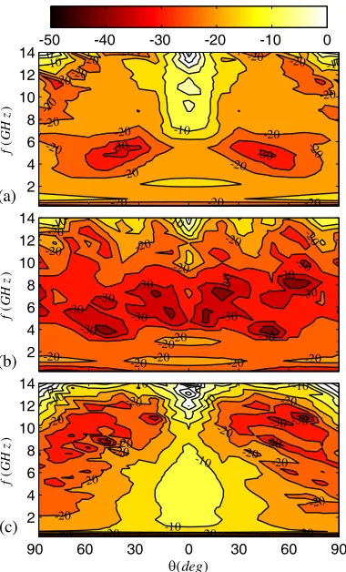
Figure 2. (color online) Bistatic RCS of a square plate of side 12 cm, covered by a inhomogeneous
plasma with the maximum electron density of ne0 = 5×10¹⁷m−3 and magnetic field intensity of (a)
B = 0, (b)B = 0.25 T, and (c) B = 0.4 T at the collision frequency of νc = 1 GHz, and inhomogeneity length scale of σne= 5 cm.
Figure 2 represents contours of the bistatic RCS of the conductive plate at (f −θ) plane, for the maximum number density of n0 = 5×10¹⁷m−3, collision frequency of νc = 1 GHz, and three different
that the maximum RCS reduction occurs aroundθ=±45◦ for the wave frequency of f 5 GHz. The corresponding RCS is approximately−30 dB.m2. The RCS reduction in the backward direction is much
weaker with the maximum up to−15 dB.m2 around thef = 5 GHz. The backscattered RCSR decreases
with increase of the wave frequency.
When a magnetic field of intensity B = 0.25 T is applied, Fig. 2(b) shows that the RCS reduction is considerably improved, reaching−40 dB.m2 around f 7 GHz. As the electron cyclotron frequency is ωb 4.4 Grad/s or νb = ωb/2π 7 GHz, the improvement in the RCS reduction is attributed to the resonant absorption. The most important point is the significant increase in the frequency range (bandwidth) and angular width of the RCSR in the presence of the magnetic field. Therefore, the enhancement in the RCS reduction can not be merely attributed to the resonant absorption and other mechanism, such as wave bending which is more efficient in the presence of the magnetic field, may play a significant role. It is also noted that the reduction in the backscattered RCS is remarkably improved. With increase of the magnetic field intensity to 0.4 T, the situation is worsened, and both the bandwidth and angular width of the RCSR are reduced. The maximum RCSR is also reduced and shifts towards f 11 GHz which coincides with the corresponding electron cyclotron frequency in this case. To explain the lower RCSR at higher magnetic fields, it is noted that the electron gyration radius decreases with increase of the magnetic field and may become even smaller than the electron mean free path. Then the effective collision frequency between the electrons and neutrals is reduced, and as a result, the wave absorption is suppressed.
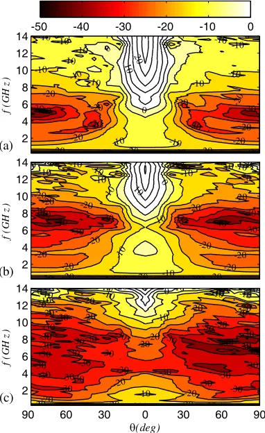
Now, the collision frequency is increased toνc = 10 GHz, and the corresponding contours of bistatic RCS are shown in Fig. 3. From comparison of Figs. 2(a) and 3(a), it is seen that with increase ofνc the maximum, bandwidth, and angular width of RCSR all are increased. The reduction in backscattered RCS is also significantly improved. In the presence of a magnetic field of intensityB = 0.25 T, Figs. 2(b) and 3(b) show that the RCSR forνc = 10 GHz is much better thanνc = 1 GHz, except for backscattered
30 30 30 -30 -20 -20 -20 -20 -20 -20 -20 -20
-20 -20 -20
-20 -20 -20 -20 -20 -20 -10 -10 -10 10 -10 0 -20 -20 -20 -20 10 -30 -30 -20 -20 -20-20 0 -30 -30 -30 -30 -30 -20 -30 -30 -30 -30 -30 -20 -20 -20 -10 (a) f ( GH z ) 2 4 6 8 10 12
14 -50 -40 -30 -20 -10 0
-30 -30 -30 -30 -30 -30 -30 -30 -30 -30 -20 -20 20
-20 -20 -20
-20 -20 0 -40 -40 -40 -30 -30 -20 -40 -30 -40 -40 (b) f ( GH z ) 2 4 6 8 10 12 14 40 -30 -30 -30 -30 30 30 30 -30 -30 -30 -20 -20 -20 -20 -20 -20 -20 -20 -20 -20 -20 -20 -20 -10 10 -10 -10 -10 0 0 1 -40 -30 10 -40 (c)
T(deg)
f
(
GH
z
)
90 60 30 0 30 60 90
2 4 6 8 10 12 14
RCSR at higher wave frequency. From Fig. 3(c) it is clearly seen that the backscattered RCS at high wave frequencies increases with increase of the collision frequency and magnetic field intensity. From comparison of Figs. 2(c) and 3(c) it is inferred that with increase of collision frequency, the maximum RCSR shifts to lower wave frequencies.
Contours of bistatic RCS forνc = 60 GHz, and for the same plasma number density and magnetic field intensities as in Figs. 2 and 3 are depicted in Fig. 4. It is seen from Fig. 4(a) that with further increase of νc, the RCSR is improved for wave frequencies below 10 GHz, while the reverse is true for higher frequencies. The problem is more severe for the backscattered component. The same trends are observed in the presence of the magnetic field if we compare Fig. 4(b) with 3(b). A detailed comparison of Figs. 2(b), 3(b), and 4(b) reveals that the maximum, bandwidth, and angular width of RCSR first increase with increase of νc from 1 GHz to 10 GHz and then decrease with further increase to νc = 60 GHz. Almost the same behavior is observed in increase of the magnetic field from B = 0 to B = 0.25 T, and then toB = 0.4 T. Therefore, it is concluded that for a plasma shroud of the maximum plasma number density of n0 = 5×10¹⁷m−3, the optimum RCSR is obtained for νc = 10 GHz and
B = 0.25 T.
-40 -30 -30
-30 -30
-30 -30 -30
30 30
30
-30 -30 -30
-30 -20 -20 -20
-20 -10 -10 -10 -10 -10 -10 0 0
-20 -20 -20
-20 -20 -30 -30 -40 -30 -40 -40 -30 -40 -30 -40 -20 -10 -30 -40 -20 (a) f ( GH z ) 2 4 6 8 10 12
14 -50 -40 -30 -20 -10 0
-40 -40 -40 -30 -30 -30 30 30 30 -30 -30 -30 -30 -20 -20 -20 -20 -20 -20 -10 -10 10 -10
-20 -20 -20
-20 -20 0 -30 -20 -30 -40 -40 -30 -30 (b) f ( GH z ) 2 4 6 8 10 12 14 -40-40 -30 -30 30 30 30 -30 -30 -30 -2 0 -20 -20 -20 -20 -20 -20 -20 -20 -10 -10 -10 -10 -10 0 -20 -30 -40 -40 -30 -30 (c)
T(deg)
f
(
GH
z
)
90 60 30 0 30 60 90
2 4 6 8 10 12 14
Figure 4. (color online) The same as Fig. 2, but forνc= 60 GHz.
Figure 5 displays the wave frequency corresponding to the maximum RCSR,fmax, as a function of
0 0.1 0.2 0.3 0.4 0.5 3 6 9 12 15
B (T ) fma x (G H z )
Figure 5. (color online) The frequency profile corresponding to the maximum RCSR as a function of
the applied magnetic field intensity, for different collision frequencies: νc = 300 MHz (solid),νc = 1 GHz (dashed), νc = 10 GHz (dotted-dashed), and νc = 60 GHz (dotted). The maximum electron density is ne0= 5×10¹⁷m−3 and the inhomogeneity length scale isσne= 5 cm.
40 40 40 -30 -30 30 30 30 -30 -30 -20 -20 -20 -20 -20 -20 -20 -20 -20 -20 -20 -20 10 -10 -10 -10 0 0 -10 -10 -10 10 -20 -20 -20 -20 -10 -30 20 -30 -40 -30 -20 -10 (a) f( G H z ) 2 4 6 8 10 12
14 -50 -40 -30 -20 -10 0
-30 -30 -30 30 -30 -30 -30 -20 -2 0 -20 -20 -20 -20 -20 -20 -20 -20 -20 -20 -10 -10 -10 0 0 -10 -10 10
-10 -10
-20 -20 -10 0 0 (b) f( G H z ) 2 4 6 8 10 12 14 -30 -30 -30 -30 -30 -30-30 -30 -20 -20 -20 -20 -20 -20 -20 -20 -20 -20 -20 -10 -10 -10 0 0 -10 -10 10 -20 -20 -10 -10 -30 -10 -20 -30 -10 -40 20 0 -40 -20 0 (c) T(deg) f( G H z )
90 60 30 0 30 60 90
2 4 6 8 10 12 14
Figure 6. (color online) The same as Fig. 2, but forne0 = 5×10¹⁶m−3 and νc = 10 GHz.
B > 0.5 T. Therefore, high electron-neutral collision rate suppress the resonant absorption and shifts the maximum RCSR to lower frequencies.
Now we study the effects of plasma number density on the RCSR in a magnetized plasma. To this end, Fig. 6 represents contours of RCS in (f −θ) plane at n0 = 5×10¹⁶m−3, νc = 10 GHz and
-30 -30 -30 -30 -30 -30 -30 -20 -20 -20 -20 -20 -20 -20 -20 -20 -20 -20 -20 -10 -10 -10 0 0 -10 -10 10 -20 -20 -10 -10 -30 -30 20 -10 -40 (a) f( G H z ) 2 4 6 8 10 12
14 -50 -40 -30 -20 -10 0
-30 -30 30 30 -30 -30 -30 -20 -20 -20 -20 -20 -20 -20 -20 -20 -20 -20 -20 -20 -10 -10 -10 -10 0 -20 -30 -20 -20 -30 10 -20 -20 -20
-20 -20 -30 -30 -20 -30 (b) f( G H z ) 2 4 6 8 10 12 14 -20 -20 -20 -20 -20 -3 0 -30 -30 -30 -30 -30 -30 -30 -10 -10 -20 -20 -20 -30 -20 -20 -20 -30 -20 -20 0 0 -30 (c) T(deg) f( G H z )
90 60 30 0 30 60 90
2 4 6 8 10 12 14
Figure 7. (color online) Bistatic RCS of a square plate of side 12 cm, covered by a inhomogeneous
plasma with the maximum electron density of (a) ne0 = 5×10¹⁵m−3, (b) ne0 = 5×10¹⁶m−3, and
(c) ne0 = 5 ×10¹⁷m−3 and the magnetic field intensity of B = 0.25 T at the collision frequency of
νc = 1 GHz, and inhomogeneity length scale ofσne= 5 cm.
backscattered component and for angles close toθ= 0. The maximum RCSR for the backscattered wave is also remarkably reduced. While in an unmagnetized plasma the maximum backward RCSR reaches 40 dB.m2 for n0 = 5×10¹⁷m−3, it is only 10 dB.m2 for n0 = 5×10¹⁶m−3. The situation becomes
even worse in the presence of the magnetic field, as seen from comparison of Figs. 3(b) and 6(b). The backscattered RCS is significantly reduced in Fig. 3(b) while it shows a much lower reduction in Fig. 6(b). These points are clearly demonstrated in Fig. 7 which shows contours of RCS in (f −θ) plane at νc = 1 GHz, B = 0.25 T, for three different values of the plasma number density. The bandwidth of RCSR is significantly enhanced by increasing the plasma number density. However, the most important effect is the improvement of the RCSR for the backscattered wave. It is noted that increase of the plasma number density to much higher values (e.g., n0 = 5×10¹⁸m−3) leads to more intense wave
reflection and thus to lower RCS reduction.
To scrutinize the effects of the length scale of the plasma inhomogeneity on the RCSR, Fig. 8 represents contours of RCSR for the same magnetic field intensity, collision frequency, and plasma number densities as in Fig. 7, but for different inhomogeneity length scales (σ = 10 cm). It should be noted that by increasing the inhomogeneity length scale, the increment of the plasma shroud thickness has also been considered proportionally. It is noted from Figs. 7(a) and 8(a) that forn0= 5×10¹⁵m−3,
increase ofσfrom 5 cm to 10 cm results in much lower RCSR at high frequencies. The situation is slightly improved with increase of the plasma number density to 5×10¹⁶m−3, butσ = 5 cm still provides much better RCSR. With further increase of n0 to 5×10¹⁷m−3, the situation changes dramatically. Now
The maximum RCSR is shown in Fig. 9 as a function of σ, atn0 = 1017m−3 and νc = 1 GHz, for
three different values of the magnetic field intensities. In the absence of the magnetic field, the maximum RCSR always increases with increase of the σ. It shows a moderate growth rate up to σ = 5 cm, then an abrupt rise form 5 cm to 10 cm, and thereafter reaches a steady state with a very small growth rate. In the presence of the magnetic field, the maximum RCSR increases with σ, reaches a maximum at σ = 5 cm, and then decreases up to σ = 10 cm. For larger values ofσ, the maximum RCSR arrives in
50 40 40 40
-30 -30 30 -30 -30 -2 0 -20 -20 -20 -20 -20 -20 -20 -20 -10 -10 -10 -10 -10 -10 -10 -10 0 0 10 20 -40 -30 -30 -10 -10 -20 -10 -10 0 -10 0 0 (a) f( G H z ) 2 4 6 8 10 12
14 -50 -40 -30 -20 -10 0
40 40 -30 -3 0 -30 30 30 -30 -30 -30 -30 -20 -20 -20 -20 -20 -20 -20 -20 -20 -20 -20 -20 -20 -10 -10 -10 -10 -10 -10 -10 -10 -10 -10 0 0 10 0 0 -10 -40 -20 -10 -30 -20 -20 -40 (b) f( G H z ) 2 4 6 8 10 12 14 -40 -30 -30 -30 -30 30 30 30 -30 -30 -30 -30 -30 -30 -30 -20 -20 -20 -20 -20 -10 -10 -10 -10 -20 -20 -20 20 -20 -20 0 0 0
020 10 20 10 20 10
-20 -30 -30 -20 30 30 -30 -20 -10 -30 -30 -30 30 -30 -30 -30 -10 -40 -30 -30 -30 -30 -30
-30 -20 -30
-10 30 -1040
40 (c) T(deg) f( G H z )
90 60 30 0 30 60 90
2 4 6 8 10 12 14
Figure 8. (color online) The same as Fig. 7, but forσne= 10 cm.
0 5 10 15 20
0 20 40 60
Vne(cm)
RC S Rma x (d B .m 2)
Figure 9. (color online) Maximum RCS reduction of backscattered component for a inhomogeneous
plasma shroud with the maximum electron density of ne0 = 1×10¹⁷m−3 at the collision frequency of
a steady state in which it increases very slowly. The maximum RCSR decreases with increase of the magnetic field from 0.25 T to 0.4 T. Another important point is that forσ <6 cm, the maximum RCSR in the presence of the magnetic field is always larger than its value in the absence of the magnetic field. Finally, Fig. 10 represents RCSR as a function of wave frequency at B = 0.25 T, νc = 1 GHz, n0 = 5×10¹⁶m−3, for three different values of σ. The maximum RCSR is equal to 12 dB.m2 for
σ = 2 cm, reaches 21 dB.m2 at σ = 5 cm, and then decreases to 10 dB.m2 at σ = 10 cm. We also note that with increase ofσ, the frequency corresponding to maximum RCSR shifts to lower wave frequencies. Moreover, the bandwidth of RCSR decreases with increase of σ. While it is approximately 7 GHz for σ= 5 cm, its value for σ= 10 cm is 4 GHz. Therefore, in terms of the bandwidth and maximum RCSR, σ= 5 cm is the optimum value for the length scale of the plasma inhomogeneity.
4 6 8 10 12
0 5 10 15 20 25
f (GHz )
RC
S
R
(d
B
.m
2 )
Figure 10. (color online) Backscattered RCS reduction for a inhomogeneous plasma shroud with the
maximum electron density ofne0= 5×10¹⁶m−3 at the collision frequency ofνc = 1 GHz, and magnetic
field intensity ofB = 0.25 T for different inhomogeneity length scale of: σ= 2 cm (solid), 5 cm (dashed), and 10 cm (dotted-dashed).
4. SUMMARY AND CONCLUSION
An optimization study of RCS reduction by an inhomogeneous magnetized plasma is presented in the framework of recursive convolution FDTD method. Numerical simulations of the model equations are utilized to obtain the bistatic RCS of a flat square conductive plate of side 12 cm, covered by a collisional inhomogeneous plasma shroud. The plasma number density decreases with distance from the plate surface and a static magnetic field is applied perpendicular to the plate. We have studied the effects of variation in the magnetic field intensity, electron-neutral collision frequency, plasma number density, and the length scale of the plasma inhomogeneity on the bistatic RCS reduction by the plasma shroud and the main results are summarized as follows
For a plasma number density of 5×10¹⁷m−3 and collision frequency of 1 GHz, contours of bistatic RCS in (f −θ) plane show that in the absence of the magnetic field, the maximum RCSR occurs around θ ±45◦, for the wave frequency of 5 GHz. The RCSR for the backscattered wave is much weaker and decreases as the wave frequency is increased. In the presence of a magnetic field of intensity B = 0.25 T, the RCSR is significantly improved, and its maximum, bandwidth, and angular width all are enhanced. The wave frequency of maximum RCSR shifts to 7 GHz, indicating the dominance of the resonant absorption. Increase of the magnetic field toB= 0.4 T results in a weaker RCSR such that its maximum, bandwidth, and angular width are reduced. This effect is attributed to the smaller electron gyration radius and thus lower effective collision frequency at higher magnetic fields.
At low collision frequencies, the wave frequency corresponding to maximum RCSR decreases with increase of the magnetic field intensity up to 0.1 T and then increases with further increase of the magnetic field. Above 0.1 T,fmaxcoincides with the electron gyration radius, indicating the dominance
of the resonant absorption over the collisional absorption. However, at high collision frequencies, the resonant absorption is suppressed, andfmax hardly change with B above 0.1 T.
When the plasma number density is reduced, the RCS reduction is significantly suppressed, especially for the backscattered component and angles close to θ = 0. The maximum RCSR and bandwidth are reduced, and these effects are prominent in the presence of the magnetic field. Increase of the plasma number density to much higher values leads to more intense wave reflection and thus to poor RCS reduction.
About the effects of the length scale of plasma inhomogeneity, it is found that at low plasma number densities, a plasma with length scale of σ = 5 cm provides much better RCSR than a plasma withσ= 10 cm. However, at high plasma number densities and for directions with θ larger than±30◦, a plasma withσ = 10 cm demonstrates relatively higher RCSR. Again, for smaller angles and specially for the backscattered wave, the plasma with σ= 5 cm is the preferred choice of the RCSR.
For a plasma number density of 1017m−3 and collision frequency of 1 GHz, the maximum RCSR
in an unmagnetized plasma always increases with increase of σ showing a step rise around σ = 6 cm and a much lower growth for smaller and larger σ. However, in the presence of the magnetic field, the maximum RCSR increases up to σ = 5 cm, then decreases up to σ = 10 cm, and thereafter remains almost unchanged. The bandwidth and frequency corresponding to maximum RCSR decrease with increase of σ.
From our parametric study of the bistatic RCSR, it is concluded that a plasma with maximum number density of 5×10¹⁷m−3, length scale of σ = 5 cm, and collision frequency of νc = 10 GHz with a perpendicularly applied magnetic field of intensity B = 0.25 T provides the optimum RCSR in terms of the maximum reduction, bandwidth, and angular width in the wave frequency range of 1–14 GHz. From applicability perspective, this study represents optimal values of plasma parameters for aerospace and ground surface applications at atmospheric pressures. Also, it emphasizes the necessity of using an external magnetic field to achieve strong resonance absorption for satellite applications at low collision frequencies.
REFERENCES
1. Singh, H., S. Antony, and R. M. Jha, Plasma-Based Radar Cross Section Reduction, Springer,, Singapore 2016.
2. Vidmar, R., “On the use of atmospheric pressure plasmas as electromagnetic reflectors and absorbers,”IEEE Transactions on Plasma Science, Vol. 18, No. 4, 733–741, 1990.
3. Stalder, K. R., R. J. Vidmar, and D. J. Eckstrom, “Observations of strong microwave absorption in collisional plasmas with gradual density gradients,”Journal of Applied Physics, Vol. 72, No. 11, 5089–5094, 1992.
4. Srivastava, A. K., G. Prasad, P. K. Atrey, and V. Kumar, “Attenuation of microwaves propagating through parallel-plate helium glow discharge at atmospheric pressure,”Journal of Applied Physics, Vol. 103, No. 3, 033302, 2008.
5. Yin, X., H. Zhang, S.-J. Sun, Z. Zhao, and Y.-L. Hu, “Analysis of propagation and polarization characteristics of electromagnetic waves through nonuniform magnetized plasma slab using propagator matrix method,”Progress In Electromagnetics Research, Vol. 137, 159–186, 2013. 6. Hu, B. J., G. Wei, and S. L. Lai, “SMM analysis of reflection, absorption, and transmission from
nonuniform magnetized plasma slab,”IEEE Transactions on Plasma Science, Vol. 27, No. 4, 1131– 1136, 1999.
7. Yee, K., “Numerical solution of initial boundary value problems involving maxwells equations in isotropic media,”IEEE Transactions on Antennas and Propagation, Vol. 14, No. 3, 302–307, 1966. 8. Huang, S. and F. Li, “Finite-difference time-domain simulation of electromagnetic propagation in
9. Jiang, Z., X. Hu, M. Liu, C. Lan, S. Zhang, Y. He, and Y. Pan, “Attenuation and propagation of a scattered electromagnetic wave in two-dimensional atmospheric pressure plasma,”Plasma Sources Science and Technology, Vol. 16, No. 1, 97–103, Dec. 2006.
10. SChung, . S. M., “FDTD simulations on radar cross sections of metal cone and plasma covered metal cone,”Vacuum, Vol. 86, No. 7, 970–984, 2012.
11. Chaudhury, B. and S. Chaturvedi, “Three-dimensional computation of reduction in Radar cross section using plasma shielding,”IEEE Transactions on Plasma Science, Vol. 33, No. 6, 2027–2034, 2005.
12. Chaudhury, B. and S. Chaturvedi, “Study and optimization of plasma-based radar cross section reduction using three-dimensional computations,”IEEE Transactions on Plasma Science, Vol. 37, No. 11, 2116–2127, 2009.
13. Chaudhury, B. and S. Chaturvedi, “Comparison of wave propagation studies in plasmas using three-dimensional finite-difference time-domain and ray-tracing methods,” Physics of Plasmas, Vol. 13, No. 12, 123302, 2006.
14. Luebbers, R. J., F. Hunsberger, and K. S. Kunz, “A frequency-dependent finite-difference time-domain formulation for transient propagation in plasma,” IEEE Transactions on Antennas and Propagation, Vol. 39, No. 1, 29–34, 1991.
15. Luebbers, R. J. and F. Hunsberger, “FDTD for Nth-order dispersive media,” IEEE Transactions on Antennas and Propagation, Vol. 40, No. 11, 1297–1301, 1992.
16. Hunsberger, F., R. Luebbers, and K. Kunz, “Finite-difference time-domain analysis of gyrotropic media. I. Magnetized plasma,”IEEE Transactions on Antennas and Propagation, Vol. 40, No. 12, 1489–1495, 1992.
17. Kelley, D. and R. Luebbers, “Piecewise linear recursive convolution for dispersive media using FDTD,” IEEE Transactions on Antennas and Propagation, Vol. 44, No. 6, 792–797, 1996.
18. Liu, S. and S. Zhong, “FDTD study on scattering for conducting target coated with magnetized plasma of time-varying parabolic density distribution,” Progress In Electromagnetics Research M, Vol. 22, 13–25, 2012.
19. Sullivan, D., “Frequency-dependent FDTD methods using Z transforms,” IEEE Transactions on Antennas and Propagation, Vol. 40, No. 10, 1223–1230, 1992.
20. Sullivan, D., “Z-transform theory and the FDTD method,”IEEE Transactions on Antennas and Propagation, Vol. 44, No. 1, 28–34, 1996.
21. Kashiwa, T. and I. Fukai, “A treatment by the FD-TD method of the dispersive characteristics associated with electronic polarization,” Microwave and Optical Technology Letters, Vol. 3, No. 6, 203–205, 1990.
22. Joseph, R., S. Hagness, and A. Taflove, “Direct time integration of Maxwell’s equations in linear dispersive media with absorption for scattering and propagation of femtosecond electromagnetic pulses,”Optics Letters, Vol. 16, No. 18, 1412–1414, 1991.
23. Gandhi, O. P., B. Q. Gao, and J. Y. Chen, “A frequency-dependent finite-difference time-domain formulation for general dispersive media,” IEEE Transactions on Microwave Theory and Techniques, Vol. 41, No. 4, 658–665, 1993.
24. Laroussi, M. and J. Roth, “Numerical calculation of the reflection, absorption, and transmission of microwaves by a nonuniform plasma slab,” IEEE Transactions on Plasma Science, Vol. 21, No. 4, 366–372, 1993.
25. Petrin, A., “On the transmission of microwaves through plasma layer,” IEEE Transactions on Plasma Science, Vol. 28, No. 3, 1000–1008, 2000.
26. Tang, D., A. Sun, X. Qiu, and P. Chu, “Interaction of electromagnetic waves with a magnetized nonuniform plasma slab,”IEEE Transactions on Plasma Science, Vol. 31, No. 3, 405–410, 2003. 27. Foroutan, V., M. N. Azarmanesh, and G. Foroutan, “FDTD simulation of radar cross section
28. Chung, S. S. M. and Y. C. Chuang, “Simulation on change of generic satellite radar cross section via artificially created plasma sprays,” Plasma Sources Science and Technology, Vol. 25, No. 3, 2016.
29. Kunz, K. S. and R. J. Luebbers,The Finite Difference Time Domain Method for Electromagnetics, CRC Press, Boca Raton, 1993.
30. Goldston, R. J. and P. H. Rutherford,Introduction to Plasma Physics, IOP, London, U.K., 1995. 31. Taflove, A. and S. C. Hagness, Computational electrodynamics: the finite-difference time-domain
method, Artech House, Boston, Mass., 2000.