Arc-Monopole Coupled DRA
Bratin Ghosh*, Devabathini Kiranmayi, and Raj Mohan Mandal
Abstract—In this work, characteristics of an arc-monopole loaded with a DRA is analyzed. It is observed that the arc-monopole can be used to effectively couple to multiple DRA modes and generate dual/triple/wideband topologies. The structure is easy to fabricate with no additional substrate or matching slot/vias required to excite the multiple DRA modes. In addition, both broadside and monopole like patterns are obtained for the dual/triple band configurations which are suitable for communication with satellite or airborne targets and for surface-to-surface communication. The enhanced radiation in the source plane for the monopole like pattern can be effectively used to communicate with preferred targets or enhance the range in the direction of interest. In addition, the arc-monopole can be suitably located to couple the source mode to the DRA modes to generate broadband behavior.
1. INTRODUCTION
The dielectric resonator antenna (DRA) has emerged as an effective radiating element for low-loss and broadband applications in the microwave and millimeter wave frequency ranges [1]. The low-loss nature is primarily attributed to the absence of conductor and surface-wave loss. In addition, the DRA can be fed effectively by a number of feed mechanisms. The DRA feeds which have been investigated till now include the coax-probe feed [2, 3] the microstrip slot-coupled feed to the DRA [4–6] the coplanar waveguide feed to the DRA [7], the rectangular waveguide feed [8, 9] and the conformal strip excitation to the DRA [10].
In most of the above feed types, a single mode has been excited in the DRA with good coupling. Broadband DRA structures based on the multi-layer DRA configuration have been also reported, where broadbanding is achieved by appropriately choosing the number of layers, layer permittivities and thicknesses to couple multiple DRA modes or the DRA mode to the source resonance ([11–13]).
A dual-band rectangular DRA fed by a microstrip-slot was reported in [14], with a wide-band configuration reported using a strip fed configuration. It was found that the presence of the backing substrate was necessary for the dual-band case in order to match the impedances of the two widely spaced DRA modes. The wide-band design could be implemented using a relatively simpler strip fed configuration fed through a ground plane, due to the relative proximity of the merging DRA modes. Further, the excitation of the slot-mode in between the two resonant DRA modes prevents the merging of the DRA modes to generate the wide-band behavior.
A circularly polarized dual-band DRA using a L-probe feed in a zonal slot loaded backing cavity was addressed in [15]. Strip fed and quadrature strip coupled circularly polarized dual-band DRAs were reported in [16]. To realize the dual-band design in [16], a matching slot is placed below the DRA to improve the match, together with a microstrip feed with a via through the substrate for exciting the feeding strip. As in [14], the microstrip feed with via arrangement was necessary to match to the two
Received 12 August 2015, Accepted 16 October 2015, Scheduled 28 October 2015
* Corresponding author: Bratin Ghosh ([email protected]).
distinct DRA modes. The feed arrangement could be simplified for the wide-band design in [16], with the feeding strip fed through the ground plane without a backing substrate or without any matching slot.
In the following work, generation of multiband and wideband behavior for a arc-monopole coupled to a DRA is investigated. The full-wave Green’s function technique is used for the analysis of the antenna structure. It is observed that the arc-monopole can be used to couple to two DRA modes to generate dual-band characteristics. The design offers simplicity of fabrication, without a backing substrate or matching slots/vias to achieve match at the two bands.
In addition, the structure can be also used for the bandwidth enhancement of the arc-monopole by coupling the monopole resonance with the DRA mode. It is also seen that with the appropriate choice of DRA permittivity and the probe location, the structure can be used to couple to three DRA modes for generation of tri-band behavior. Also, both broadside and end-fire patterns can be obtained, which are specifically useful for naval and defense applications for communication with satellite/air borne targets and surface to surface communication with marine/land vehicles respectively.
In addition, in certain cases it is seen the end-fire radiation is dominant in one plane and relatively weak in the orthogonal plane. This characteristic is very suitable for communicating with friendly targets at sea or land and also to minimize interference from a given direction. Also, in conjunction with whip antennas for omnidirectional coverage on board naval vehicles for surface to surface communication, the dominant radiation in one plane of radiation for the proposed antenna structure can be used to enhance the range in the preferred direction of interest.
In addition to the above, for some other cases, omnidirectional end-fire patterns are also obtained for the proposed antenna structure. This makes the arc-monopole loaded DRA a easy to realize and very versatile antenna element for naval and land defense applications.
2. FORMULATION OF THE PROBLEM
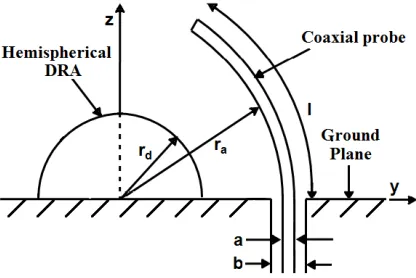
The antenna configuration is shown in Fig. 1. The arc-monopole, of radius of curvature ra, is located
in the vicinity of the DRA, of radiusrd and dielectric constantεr. The length and wire diameter of the
arc-monopole are land arespectively.
Figure 1. Arc-monopole coupled DRA.
The solution to the above antenna structure can be obtained following the procedure in [2]. The particular solutions for the magnetic and electric Green’s functions are found as:
GAJθrp = 1 r ∞ n=1 n m=0
anmdP m
n (cosθ)
dθ P
m
n (cosθ) cosm
φ−φ
ˆ
Hn(2)(k0r) ˆJn(k0r) (r < r)
ˆ
Jn (k0r) ˆHn(2)(k0r) (r > r)
(1a)
and
GFJθrp= 1 rsinθ
∞ n=1 n m=1
dnmPnm(cosθ)Pnm
cosθsinmφ−φ
ˆ
Hn(2)(k0r) ˆJn(k0r) (r < r)
ˆ
Jn(k0r) ˆHn(2)(k0r) (r > r)
respectively, where
anm = −j
(2n+ 1)(n−m)!
2πnΔm(n+ 1)(n+m)! (1c)
dnm = k0m
(2n+ 1)(n−m)! 2πωε0n(n+ 1)(n+m)!
(1d)
Δm = 2 for m= 0
1 for m= 0 (1e)
In the above, Pnm(x) is the associated Legendre function of the first kind with order m and degree n. ˆ
Jn(x) and ˆH (2)
n (x) are respectively the spherical Bessel function of the first kind (Schelkunoff type) and
spherical Hankel function of the second kind (Schelkunoff type), of order n. r(r, θ, φ) andr(r, θ, φ) refer to the field and source points respectively. All other symbols have the usual meanings. The magnetic and electric homogeneous Green’s functions for the configuration are also computed and given as follows:
GArh Jθ =
1 r ∞ n=1 n m=0
−sn
ΔTM
n
anmdP m
n (cosθ)
dθ P
m
n (cosθ) cosm
φ−φHˆn(2)k0r
ˆ
Hn(2)(k0r) (r > rd) (2a)
and
GFrh Jθ =
1 rsinθ
∞ n=1 n m=1
− tn
ΔTE
n
dnmPnm(cosθ)Pnm
cosθsinmφ−φHˆn(2)k0r
ˆ
Hn(2)(k0r) (r > rd)
(2b) respectively, where
sn = ˆJn(krd) ˆJn (k0rd)−
1
√
εr
ˆ
Jn (krd) ˆJn(k0rd) (2c)
tn = ˆJn(krd) ˆJn (k0rd)−√εrJˆn (krd) ˆJn(k0rd) (2d)
ΔTMn = ˆJn(krd) ˆH(2)
n (k0rd)−
1
√
εr
ˆ
Jn (krd) ˆHn(2)(k0rd) (2e)
ΔTEn = ˆJn(krd) ˆH(2)
n (k0rd)−√εrJˆn (krd) ˆHn(2)(k0rd) (2f)
Adding the two Green’s functions for the ˆθdirected electric field due to the particular and homogeneous solutions, and replacing the particular term with the Green’s function for the ˆθ directed electric field due to the ˆθdirected current source to improve the convergence of the particular solution [17], the total Green’s function is obtained as:
G
Eθ
Jθ
= −j 4πωε0
e−jk0R
R5 R
2
k20R2−jk0R−1
cosθ−θ−r2ak20R2−3jk0R−3
sin2θ−θ
− k0
2πωε0rr
∞
n=1
2n+ 1 n(n+ 1)
n
m=0
−(n−m)!
(n+m)! sn
ΔTM
n Δm
dPnm(cosθ) dθ
dPnm(cosθ) dθ
cosmφ−φHˆn(2)k0r
ˆ
Hn(2)(k0r)
− k0
2πωε0rrsinθsinθ
∞
n=1
2n+ 1 n(n+ 1)
n
m=1
−(n−m)!
(n+m)! tn
ΔTE
n
m2Pnm(cosθ)Pnmcosθ
cosmφ−φHˆn(2)k0r
ˆ
Hn(2)(k0r) (3a)
where
R=2r2
a(1−cos (θ−θ)) +a2/4 (3b)
3. RESULTS
3.1. Dual Band Arc-Monopole
In this part, two designs of the dual-band arc-monopole are presented. For the first configuration, the arc-monopole of radiusra= 14 mm, lengthl= 15 mm anda= 1.3 mm is placed in the vicinity of a DRA
of permittivityεr = 9 and radiusrd= 12.5 mm. The antenna structures were simulated using the High
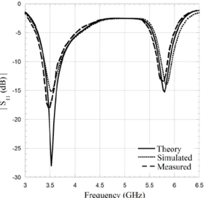
Frequency Structure Simulator (HFSS) [18]. A finite conductivity of copper of 5.8×10⁷Siemens/m for the ground plane and arc-monopole was used in the simulations. Fig. 2 shows the return loss characteristics for the antenna structure. A good agreement is seen between the measured, computed and simulated results. Two resonant dips are observed at 3.50 and 5.78 GHz corresponding to the measured results. The corresponding computed/simulated return loss dips are at 3.53 GHz (0.86% error) and 5.80 GHz (0.35% error)/5.83 GHz (0.87% error), which are in very good agreement with the measured results. The measured 10-dB impedance bandwidths at the lower and upper bands are 9.69%
Figure 2. Computed, simulated and measured return-loss characteristics of the arc-monopole coupled dual-band DRA for the first configuration. ra= 14 mm, rd= 12.5 mm, εr = 9,l= 15 mm, a= 1.3 mm.
(a) (b)
and 3.48% respectively.
The first dip is close to the source-free resonance of the dominant TE111 mode at 3.77 GHz. The
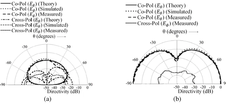
radiation pattern at the first resonant frequency is shown in Fig. 3. A broadside pattern is observed, characteristic of theTE111 mode. The cross-pol level is seen to be negligible in theφ= 90◦ plane with
the peak cross-pol low at around−13 dB atφ= 0◦.
The computed/simulated cross-pol in theφ= 90◦ plane is below−50 dB and as such could not be shown, which is also followed for subsequent figures in this work.
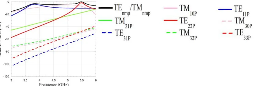
In order to examine the radiation characteristics further, the mode excitation efficiency for the antenna structure is evaluated. It is known that the resonance effect in the input impedance characteristics of an antenna is due to the inherent contribution of multiple modes, instead of a single mode. In fact, the resonant modes contributing to the peak in the input resistance might have resonant frequencies displaced from the frequency corresponding to the input resistance peak [19]. In order to investigate the excitation of modes and the nature of modal contribution to the resonances of the antenna structure considered here, the relative contribution of a mode in the peak radiated power in the far-field is computed [20].
Figure 5 shows the mode excitation versus frequency for the antenna structure. The curve labeled TE/TMnmp denotes the total radiated power due to all modes shown in the figure. It can be noted
that the Green’s function G
Eθ
Jθ
of the DRA is independent of the modal indexp and as such the
(a) (b)
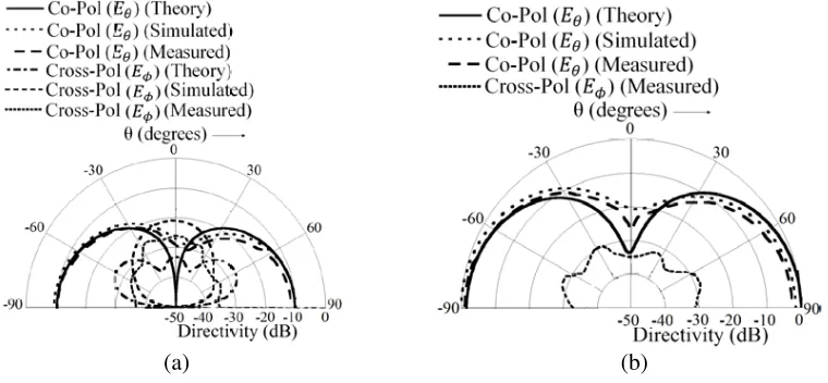
Figure 4. Computed, simulated and measured radiation patterns of the arc-monopole coupled dual-band DRA for the first configuration at the second resonance in Fig. 2. (a)φ= 0◦ plane. (b) φ= 90◦ plane.
radiation efficiency of a mode also does not depend on p. It is seen that the excitation of the TE11p
mode is stronger near the first resonance, which possessEφ andEθ as co-pol components in the φ= 0◦
andφ= 90◦ planes respectively. (The source free field distribution for the mode is shown in Fig. 19(a).) The cross-pol in the φ = 0◦ plane (Eθ) is contributed by the weaker excitation of the TM10p mode
(Fig. 19(b)), which possessEθ as co-pol at φ= 0◦.
The radiation pattern at the second resonance in Fig. 2 is shown in Fig. 4. The source-free modes in the vicinity of the resonance are theTM101and theTE221modes with resonant frequencies at 5.50 GHz
and 5.47 GHz respectively. The source free field distribution of theTE221 mode is shown in Fig. 19(c).
The pattern characteristics in Fig. 4 the φ = 90◦ plane is similar to the monopole like pattern of the pureTE221mode with almost insignificant cross-pol. It is also observed from Fig. 5 that the excitation
of the TE221 mode is strong, with the excitation of the TE11p and TM21p modes comparable to the
excitation of the TM101 mode. It can also be noted that due to the tighter coupling of the source to
the DRA, the radiation in the φ= 90◦ plane is significantly stronger compared to the radiation in the φ = 0◦ plane. The cross-pol level is very low in both planes. The difference between the computed and simulated cross-pol in Fig. 4(a) is due to the finite conductivity of the ground plane/arc-monopole taken into account in the simulations with an infinite conductivity assumed for the computations.
It is thus seen that that broadside pattern characteristics are obtained at the first resonance and end-fire characteristics at the second resonance. For the antenna mounted on naval/land vehicles, the broadside radiation at the first resonance can be used for satellite communication or communication with air-borne targets. The end-fire pattern characteristics at the second resonance can be used for naval or land surface-to-surface communication. The enhanced radiation in the φ= 90◦ plane compared to theφ= 0◦ plane is particularly suitable for communication with friendly targets. The antenna can also be used as part of mechanically steerable antenna systems on board naval or land vehicles and can be steered with a rotating ground plane to the direction of interest along the plane of enhanced radiation. In conjunction with omnidirectional whip antennas on marine/land vehicles, the antenna structure can also be used for enhancing the range of sight in a preferred direction. In addition, it can be used to reduce interference and scattering from an undesired target.
The measured gains at the lower and upper resonant frequencies are at 4.8 dBi and 5.9 dBi respectively. The radiation efficiency was measured for the antenna structure using the Wheeler’s cap method [21]. The measured antenna efficiency at the two resonant bands are 96.50% and 97.30% at the first and second resonant frequencies respectively which compare well with the simulated efficiencies of 98.29% and 99.13% respectively. The loss can be attributed to the finite conductivity of the ground plane and the monopole, the dielectric loss and the edge currents on the ground plane.
The next dual-band design configuration is presented to offer relatively omnidirectional coverage
in the azimuthal plane at the two bands of operation by moving the arc-monopole away from the DRA surface to strengthen the pattern at φ = 0◦. In addition, the permittivity of the DRA is increased to εr = 16 to reduce the resonant frequencies of the higher order end-fire modes. The return loss
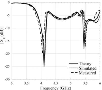
characteristics of the antenna is shown in Fig. 6 with ra= 20 mm. The measured return loss dips are
at 4.05 and 5.50 GHz, with the computed/simulated dips at 4.10 GHz (1.23% error)/4.13 GHz (1.98% error) and at 5.45 GHz (−0.91% error)/5.50 GHz. The measured 10-dB return loss bandwidths for the first and second resonances are at 4.21% and 1.82% respectively.
The modes in the vicinity of the first dip in this case are the TM101 and the TE221 modes with
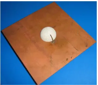
source-free resonant frequencies at 4.02 GHz and 4.18 GHz respectively. The radiation characteristics at the first resonance is shown in Fig. 7. Monopole like patterns are observed in the φ= 0◦ and φ= 90◦ planes due to the endfireTM101/TE221modes. This can also be observed from the mode-excitation plot
in Fig. 9 where the excitation efficiency of theTM101/TE221 modes are stronger at the first resonance.
The low-cross pol in theφ= 0◦plane is due to the weakly excitedTE11p mode at resonance. Compared
to Fig. 4, it is also observed that the radiation in theφ= 0◦ plane is significant in this case. A pattern asymmetry is seen in the φ= 90◦ plane due to the source.
(a) (b)
Figure 7. Computed, simulated and measured radiation patterns of the arc-monopole coupled dual-band DRA for the second configuration at the first resonance in Fig. 6. (a)φ= 0◦ plane. (b) φ= 90◦ plane.
(a) (b)
For the second resonance, the source free modes close to the resonance are the degenerate TE331
and theTE311modes with a source-free resonance at 5.42 GHz. The source free field distribution for the
TE331and theTE311modes are shown in Figs. 19(d) and (e) respectively. The radiation pattern at this
resonance is shown in Fig. 8. Monopole like patterns are observed in both φ= 0◦ and φ= 90◦ planes. It is seen from the mode excitation plot in Fig. 9 that the excitation of the TM10p mode is stronger
than the TE331 mode at the resonance. This contributes to the relatively strong excitation of the Eθ
component atφ= 0◦. As such, the strength of the pattern atφ= 0◦ is also improved, particularly near the horizon compared to Fig. 4.
The gains at the first and second bands in this case are measured at 5.0 dBi and 5.1 dBi respectively. The measured antenna efficiency at the first and second resonances are at 97.90% and 95.20% respectively, which can be compared to the simulated efficiency values of 99.41% and 96.54% respectively.
A photograph of the fabricated antenna prototype is shown in Fig. 10.
Figure 9. Excitation efficiency of modes with frequency for the arc-monopole coupled dual-band DRA for the second configuration.
Figure 10. Fabricated antenna prototype for the arc-monopole coupled DRA.
Figure 11. Computed, simulated and measured return-loss characteristics of the arc-monopole coupled triple-band DRA.ra= 13.5 mm,εr= 16.
Other parameters same as Fig. 2.
3.2. Triple Band Arc-Monopole
of contributing modes. Fig. 11 shows the return loss characteristics of the antenna configuration. The location of the arc-monopole is at ra = 13.5 mm with the DRA radius and the arc-monopole length
maintained constant atrd= 12.5 mm and l= 15 mm respectively.
The first resonant dip for the antenna structure is measured at 2.70 GHz, corresponding to the computed/simulated values of 2.75 GHz (1.85% error) and 2.78 GHz (2.96% error), respectively. The measured 10-dB impedance bandwidth is at 5.50%. The dominant TE111 mode with a source-free
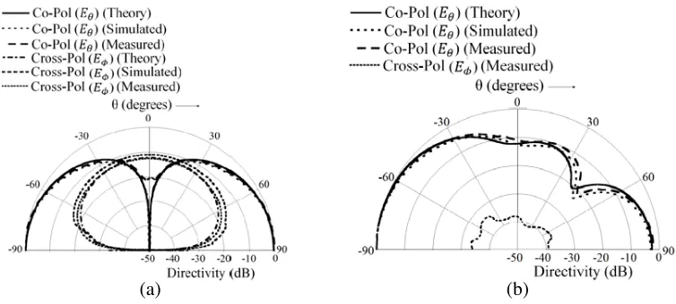
resonant frequency of 2.88 GHz principally contributes to this resonance, as in Fig. 2. This is also seen from the mode excitation plot for the antenna configuration in Fig. 15. The radiation pattern at this resonance is shown in Fig. 12. A broadside pattern is observed, as expected, with a low cross-polar component Eθ in the φ= 0◦ plane contributed by the weakly excitedTM10p mode.
The second dip in the return loss characteristics is measured at 5.60 GHz. The corresponding computed/simulated values are 5.60 GHz and 5.63 GHz (0.54% error). The 10-dB bandwidth is measured at 4.24%. The contributing source free modes near the loaded resonance are the degenerate
TE311/TE331 modes with a source-free resonance at 5.42 GHz. The radiation pattern at 5.60 GHz is
shown in Fig. 13. The radiated power is more stronger in the φ = 90◦ plane relative to the φ = 0◦ plane, due to the tighter coupling of the source to the DRA. The minimum at boresight is contributed by the pureTE331mode pattern. In addition, from Fig. 15, it can be observed that the excitation of the
(a) (b)
Figure 12. Computed, simulated and measured radiation patterns of the arc-monopole coupled triple-band DRA at the first resonance in Fig. 11. (a) φ= 0◦ plane. (b)φ= 90◦ plane.
(a) (b)
(a) (b)
Figure 14. Computed, simulated and measured radiation patterns of the arc-monopole coupled triple-band DRA at the third resonance in Fig. 11. (a) φ= 0◦ plane. (b) φ= 90◦ plane.
Figure 15. Excitation efficiency of modes with frequency for the arc-monopole coupled triple-band DRA.
TM10p andTE22p modes are strong at this frequency (though lesser than theTE331 mode), which also
contributes to the minimum in pattern at boresight. The cross-pol component (Eθ) at φ= 0◦, though
of low magnitude, is also contributed by the TM10p and TE22p modes. The difference between the
theoretical and simulated patterns at φ= 0◦ is due to the finite conductivity used in the simulations. The third resonant dip, measured at 5.95 GHz (simulated: 6.00 GHz (0.84% error), computed: 5.98 GHz (0.50% error)) is close to the source-free resonant frequency of theTE112 mode with a
source-free resonance at 5.88 GHz. The measured 10-dB bandwidth is at 3.39%. It is also seen from the mode excitation characteristics in Fig. 15 that the contribution of theTE112mode is strong at this frequency.
The radiation pattern at this frequency, shown in Fig. 14, is thus similar to the pure TE112 mode
pattern. It should be mentioned that the radiation pattern of the pure modesTE111 and TE112 modes
are the same due to degeneracy in the third modal index. The cross-polar component, Eθ at φ= 0◦ is
essentially contributed by the TM101 mode which is seen to be present along with theTE112 mode in
Fig. 15, though of a lesser magnitude.
on the input impedance characteristics at or near the resonant frequency of the mode to obtain a input resistance of 50 Ω and a reactance close to zero for impedance match with the given mode. The change in the distance between the monopole and the DRA affects the level of impedance match at the resonant frequency of a given mode and result in its excitation if the mode is matched with respect to the feed. The measured gains at the lowest, middle and the highest resonances are at 4.5 dBi, 5.8 dBi and 4.7 dBi. The measured efficiencies at the three bands are at 93.60%, 95.30% and 97.10% compared with the simulated values of 95.07%, 96.48% and 98.64% respectively.
3.3. Broadband Arc-Monopole
It is shown in this part that broad-band characteristics can be obtained with the antenna configuration by moving the arc-monopole further from the DRA and coupling of the arc-monopole resonance with the
TM101 and theTE221modes of the DRA. The parameters are the same as in Fig. 2 withra= 31.5 mm.
It might be noted that the source-free resonant frequencies of theTM101 and theTE221 modes are at
5.50 GHz and 5.47 GHz, respectively.
Figure 16. Computed, simulated and measured return-loss characteristics of the arc-monopole coupled broadband DRA. ra= 31.5 mm,εr= 9. Other parameters same as Fig. 2.
(a) (b)
The return loss characteristics for the antenna is shown in Fig. 16. The 10-dB impedance bandwidth of 23.83% is measured for the configuration. The radiation pattern at the center frequency of 4.84 GHz is shown in Fig. 17. An interesting effect is observed from the radiation characteristics. At theφ= 90◦ plane, the co-pol pattern looks different from the monopole like patterns of the arc-monopole and the
TM101/TE221 modes. It can be observed from the mode excitation plot in Fig. 18 that the excitation
efficiency of theTM10pmode is highest at 4.84 GHz. However, the excitation of theTE11pmode, though
below that of the TM10p mode is also dominant and stronger than nearby modes. The monopole like
radiation characteristics at the center frequency in the φ= 90◦ plane is thus affected by the broadside pattern of theTE111mode. In theφ= 0◦plane, this manifests in an increased cross-pol component,Eφ,
with the co-pol characteristics, Eθ unperturbed from the monopole mode. This is because the co-pol
Figure 18. Excitation efficiency of modes with frequency for the arc-monopole coupled broadband DRA.
(a) (b)
(e)
Figure 19. Source free field distributions. (a) TE111 mode. (b) TM101 mode. (c) TE221 mode. (d)
TE331 mode. (e) TE311 mode.
components of the pureTM101/TE221 and theTE111 modes are directed alongEθ andEφ respectively
atφ= 0◦. It is also observed that the pattern characteristics are stable across the impedance bandwidth. The measured gain at the center frequency is at 4.9 dBi. The measured and simulated efficiencies at the center frequency are at 96.90% and 98.32% respectively.
4. CONCLUSION
Multiband and broadband configurations of an arc-monopole coupled DRA has been investigated. The return loss and radiation characteristics of the antenna structure were analyzed. It is observed that the configuration can couple to a number of DRA modes leading to multiband/broadband topologies. The structure is simple to fabricate with no need of a backing substrate, matching slot or vias to generate multiband behavior. For the dual-band case, both broadside and monopole like patterns are obtained, which is particularly useful for naval/land vehicles, for communicating with satellite or air-borne targets and for surface-to-surface communication. The enhanced radiation in the φ= 90◦ plane for the monopole pattern can be effectively used for communicating with friendly targets or to enhance the range in the direction of interest, together with reducing interference and scattering effects from the orthogonal plane. It is also observed that triple band characteristics can be generated by increasing the permittivity of the DRA. Two broadside and a monopole like pattern are obtained for the triband case. In addition, a broadband configuration is obtained by appropriately locating the arc-monopole and coupling the arc-monopole and the DRA resonances.
REFERENCES
1. Long, S. A., M. W. Mcallister, and L. C. Shen, “The resonant cylindrical dielectric cavity antenna,”
IEEE Trans. Antennas Propag., Vol. 31, 406–412, May 1983.
2. Leung, K. W., K. M. Luk, K. Y. A. Lai, and D. Lin, “Theory and experiment of a coaxial probe fed hemispherical dielectric resonator antenna,” IEEE Trans. Antennas Propag., Vol. 41, 1390–1398, Oct. 1993.
3. Junker, G. P., A. A. Kishk, and A. W. Glisson, “Input impedance of dielectric resonator antennas excited by a coaxial probe,”IEEE Trans. Antennas Propag., Vol. 42, 960–966, Jul. 1994.
4. Leung, K. W., K. M. Luk, K. Y. A. Lai, and D. Lin, “Theory and experiment of an aperture-coupled hemispherical dielectric resonator antenna,” IEEE Trans. Antennas Propag., Vol. 43, 1192–1198, Nov. 1995.
6. Kishk, A. A., A. Ittipiboon, Y. M. M. Antar, and M. Cuhaci, “Slot excitation of the dielectric disk radiator,”IEEE Trans. Antennas Propag., Vol. 43, 198–201, Feb. 1995.
7. Kranenburg, R. A., S. A. Long, and J. T. Williams, “Coplanar waveguide excitation of dielectric resonator antennas,”IEEE Trans. Antennas Propag., Vol. 39, 119–122, Jan. 1991.
8. Leung, K. W. and K. K. So, “Rectangular waveguide excitation of dielectric resonator antenna,”
IEEE Trans. Antennas Propag., Vol. 51, 2477–2481, Sep. 2003.
9. Eshrah, I. A., A. A. Kishk, A. B. Yakovlev, and A. W. Glisson, “Theory and implementation of dielectric resonator antenna excited by a waveguide slot,” IEEE Trans. Antennas Propag., Vol. 53, 483–494, Jan. 2005.
10. Leung, K. W., “Conformal strip excitation of dielectric resonator antenna,”IEEE Trans. Antennas
Propag., Vol. 48, 961–967, Jun. 2000.
11. Chen, N. C., H. C. Su, K. L. Wong, and K. W. Leung, “Analysis of a broadband slot-coupled dielectric-coated hemispherical dielectric resonator antenna,” Microwave Opt. Tech. Lett., Vol. 8, 13–16, Jan. 1995.
12. Wong, K. L. and N. C. Chen, “Analysis of a broadband hemispherical dielectric resonator antenna with a dielectric coating,” Microwave Opt. Tech. Lett., Vol. 7, 73–76, Feb. 1994.
13. Kakade, A. B. and B. Ghosh, “Mode excitation in the coaxial probe coupled three-layer hemispherical dielectric resonator antenna,” IEEE Trans. Antennas Propag., Vol. 59, 4463–4469, Dec. 2011.
14. Fang, X. S. and K. W. Leung, “Designs of single-, dual-, wide-band rectangular dielectric resonator antennas,”IEEE Trans. Antennas Propag., Vol. 59, 2409–2414, Jun. 2011.
15. Ding, Y., K. W. Leung, and K. M. Luk, “Compact circularly polarized dualband zonal-slot/DRA hybrid antenna without external ground plane,” IEEE Trans. Antennas Propag., Vol. 59, 2404– 2409, Jun. 2011.
16. Fang, X. S. and K. W. Leung, “Linear-/circular-polarization designs of dual-/wide-band cylindrical dielectric resonator antennas,”IEEE Trans. Antennas Propag., Vol. 60, 2662–2671, Jun. 2012. 17. Leung, K. W., “Complex resonance of the circular-arc dipole antenna,”Microwave Opt. Tech. Lett.,
Vol. 39, 253–256, 2003.
18. HFSS ver. 13.0, Ansoft Corporation, Pittsburgh.
19. Kishk, A. A., “Body of revolution (BOR) — Analysis of cylindrical dielectric resonator antennas,”
Dielectric Resonator Antennas, K. M. Luk and K. W. Leung, Eds, R. S. Press, Hertfordshire, U.K., 2003.
20. Kishk, A. A. and L. Shafai, “The effect of various parameters of circular microstrip antennas on their radiation efficiency and the mode excitation,” IEEE Trans. Antennas Propag., Vol. 34, 969–976, Aug. 1986.