Papers presented in ICIREST-2018Conference can be accessed from
Abstract—This paper presents the performance of STATCOM to improve power quality and voltage stability. The STATCOM is proposed to control both active and reactive power exchange with the grid sides. It aims to provide a comprehensive control for a distributed network and improve stability. STATCOM are limited in their ability to improve the system stability margin due to restricted capability of delivering real power. However, due to its low voltage long time constant and voltage dependent energy storage, applying the supercapacitor to grid level application is challenging. This paper examines the steady state performance of three type of supercapacitor energy storage system. This paper proposes a solution to enhance the performance of the STATCOM by adding supercapacitor energy storage to the dc link of the conventional STATCOM. Supercapacitor are devices which can store significant amounts of energy and are able to quickly rele ase it and are now finding application in many power applications. This paper describes how supercapacitor best energy storage technology can be interfaced to a STATCOM unit. The aim of this work is to investigate how supercapacitor best energy storage technology can be used to enhance the capability of STATCOM units to maintain high quality of distribution voltage and improve the system stability.
Keywords: STATCOM (Static Synchronous Compensator), Supercapacitor, Voltage profile, power losses.
I. INTRODUCTION
In modern distributed network, large amount of renewable energy may be connected, which causes both voltage and frequency problem in the grid. The conventional reactive power control can only solve the voltage problem, but the frequency oscillation caused by active power swing requires active control to compensate. Increased demand on transmission absence of long term planning and the need to provide open access to generating companies and customers have created tendencies towards less security and reduced quality of supply. The FACTS technology is essential to alleviate these difficulties. The FACTS technology opens up new opportunities for controlling power, stability, power transfer capability and enhancing the usable capacity of the present, as well as new and upgraded lines. These opportunities arises through the ability of FACTS
controllers. To control the interrelated parameters that govern the operation of transforming system including series
impedance, shunt impedance, current, voltage, phase angle and the damping of oscillation.
The basic idea of FACTS is installing the power electronic devices at high voltage side of the power grid to make the whole system electronically controllable. The FACTS devices are able to provide active power and reactive power to the power grid rapidly. The power compensation achieved by FACTS devices could adjust the voltage of the whole system and the power flow could be satisfactorily controlled.
The project entails simulating a model of a complete FACTS controller using STATCOM device. FACTS devices like STATCOM, it is designed based on voltage source converter (VSC) electronic device with gate turn off thyristor and dc capacitor coupled with step down transformer tied to a transmission line. the complete model either converts ac power into dc power by VSC as a control rectifier or convert the dc power into ac power by VSC as a PWM converter, during the time of transient faults especially when there is any change in reactive power. STATCOM provide controlled VAr compensator for grid voltage support. STATCOM can be designed to also act as an active filter to absorb system harmonics. The main objective of power project is deals with the reactive power compensation that is when reactive power in the power system is decreased then STATCOM will inject the reactive power in the power system network and when surplus reactive power available in the power system is increased beyond some limits then STATCOM will absorb the reactive power. The capacitor will charged or discharged according to control logic applied to VSC in control rectifier mode or inverter mode as per the reactive power variation in the power system. For prevention of large fluctuation in dc due to variation in ac system voltage maintaining the direct voltage near the rated value and prevention of commutation failure in inverter, we use the PWM method for firing of the VSC.
In order to increase or improve the system stability margin STATCOM with supercapacitors are used. Supercapacitors have the highest capacitive density available today with densities so high these capacitors can
Improvement Of Voltage Stability Using Statcom
And Supercapacitor For Better Performance
Pranjali R. Nirvikar Prof.Vaishali Pawde
M-Tech scholar Assistant Professor TGPCET Mohgaon, Nagpur TGPCET Mohgaon, Nagpur
be used to applications normally reserved for batteries. Supercapacitors are not as volumetrically efficient and are more expensive than batteries but they do have other advantages over batteries making the preferred choice in application requiring a large amount of energy storage to be stored and delivered in bursts repeatedly. And the most significant advantages supercapacitors have over batteries in their ability to be charged and discharged continuously without degrading line batteries.
II SYSTEM OVERVIEW
STATCOM
A STATCOM (Static Synchronous Compensator) is a power electronic device using force commutated device like IGBT, GTO etc. It is a shunt, flexible AC transmission system (FACTS) device, used to compensate reactive power in a grid and by this stabilize the grid voltage. A Static Synchronous Compensator (STATCOM) is also known as Static Synchronous Condenser (STATCON). A stable grid voltage will also improve the power transmission of the system, since the transfer of power is depending on system voltage. The STATCOM is in contradiction to the more traditional static VAR compensator (SVC), not depending upon the applied voltage absorbing or injecting the demanded reactive power. This ability makes the STATCOM advantageous for regulation of the system voltage at the point of common coupling (PCC).
Figure1: Schematic representation of STATCOM
STATCOM with active power compensation could be realized by adding an element which can inject and consume active power that is store the active energy. It can be reached by parallel connection of a battery to the DC capacitor. STATCOM uses VSC technology which enables four quadrant operation in case of active power exchange possibility. It makes possible to convert AC to DC and back for active current. Usage of active power compensation has a big potential for many applications such as:
a)
Voltage and power compensation in distribution and transmission system.b)
Power compensation during short circuits and network reconfiguration.c)
Stability increasing during grid reconfiguration or generator failures.d)
Compensation of voltage dip during short time failures.WORKING PRINCIPLE OF STATCOM
To understand the working principle of STATCOM, we will first have a look at the reactive power transfer equation. Let us consider two sources V1 and V2 are connected through an impedance Z and it is shown in the figure below.
Assuming Ra=0,
Reactive power flow Q is given as Q= (V2/X)[V1Cos -V2]
In the above reactive power flow equation, angle del is the angle between V1 and V2.Thus,if we maintain angle =0 then reactive power flow will become
And active power flow will become
To summarize, we can say that if the angle between V1 and V2 is zero, the flow of active power becomes zero and the flow of reactive power depends on (V1-V2). Thus, for flow of reactive power there are two possibilities.
1) If the magnitude of V1 is more than V2,then reactive power will flow from source V1 to V2. 2) If the magnitude of V2 is more than V1, reactive
power will flow from source V2 to V1.
This Principle is used in STATCOM for reactive power control.
DESIGN OF STATCOM
1. VOLTAGE SOURCE CONVERTER(VSC)
The Voltage Source Converter is used to convert the DC input voltage to an AC output voltage. Two of the common VSC types are as below.
a)
Square wave Inverters using Gate Turn Off Thyristor: In this type of VSC, output AC voltage is controlled by changing the DC capacitor input voltage, as the fundamental component of the converter output voltage is proportional to the DC voltage.Papers presented in ICIREST-2018Conference can be accessed from GTO based type, the IGBT based VSC utilizes a fixed DC voltage and varies its output AC voltage by changing modulation index of the PWM modulator.
The VSC-based STATCOM compromises a pulse width modulation (PWM) control three phase inverter with a dc bus capacitor. In contradiction to the traditional reactive compensation, such as condenser banks, where the capacitor size is directly related to the compensating capability, the dc capacitors of the STATCOM are of no direct connection to the reactive power supply. Its only purpose is to maintain a steady state DC bus voltage. A simplified circuit scheme of a VSC STATCOM is given in figure 2.
Figure2: The VSC-STATCOM circuit scheme
1. DC CAPACITOR
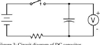
Capacitors do not play an important role in DC circuits because it is impossible for a steady current to flow a steady current. If an uncharged capacitor C is connected across the terminals of a battery of voltage V then a transient current flows as the capacitor plates charge up. However, the current stops flowing as soon as the charge Q on the positive plate reaches the value Q=CV. At this point, the electric field between plates cancels the effect of electric field generated by the battery, and there is no further movement of charge. Thus, if capacitor is placed in DC circuits then, as soon as its plate have charge of the capacitor behaves like a break in the circuit. DC capacitor is used to supply constant DC voltage to the Voltage Source Converter, VSC.
Figure 3: Circuit diagram of DC capacitor
2. INDUCTIVE REACTANCE
A Transformer is connected between the output of Voltage Source Converter and Power System. Transformer basically acts as a coupling medium. In addition, transformer neutralize harmonics content in the square waves produced by the VSC.
3. HARMONIC FILTER
Harmonic Filter attenuates the harmonics and other high frequency components due to the voltage source converter. A simplified diagram along with equivalent electrical circuit of STATCOM is shown in figure below
Figure 4: Electrical circuit of STATCOM
As can be seen from the figure above, source V1 represents the output voltage of the STATCOM. In case of reactive power demand increases in the power system, STATCOM increases its output voltage V1 while maintain the phase difference between V1 and V2 to zero(it shall be noted here that there will always exists small phase angle between V1 and V2 to cater for the leakage impedance drop in the interconnecting transformer). As V1>V2, reactive power will flow from STATCOM to the power system. Thus STATCOM, supplies reactive power and acts as reactive power generator.
Again, if the voltage of power system increase due to load flow through off, STATCOM will reduce its output voltage V1 and therefore will absorb reactive power to stabilize the voltage to normal value.
PWM MODULATION
The PWM strategies for switching the inverters are the most common ways of controlling the transistor based converter. These strategies offer a low harmonic content in the output of the inverter compare to square wave modulation (SWM).This is related to the ON/OFF time of the switches. The PWM technique yields a changing a switching time, depending on the demanded output voltage.
SUPERCAPACITOR:
parallel hybrid capacitor system are developed in comparison with pure capacitor system, which provide and improve performance in terms of efficiency, volume, thermal, cost and life time under the same STATCOM operating condition. By adding the energy storage element the STATCOM can draw and inject both active and reactive power, adding an additional degree of freedom to the system. By doing so, the power quality is improved. The demanded size of a energy storage system is depending upon the demanded control of the power fluctuations. A sensitive control will demand for a higher energy capacity than a rough one. The supercapacitor bank needs an interface for the connection to the DC bus. This could span from a simple inductance to filter out the most severe ripples.
Figure 5: The STATCOM with supercapacitor
III CONFIGURATION OF THE SYSTEM
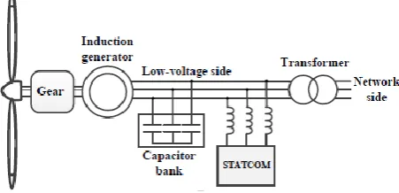
In given figure4, the induction generator, the capacitor bank, compensation system is shown. In this case the STATCOM are connected to the low voltage side of the wind turbine generator.
Figure 6: Configuration of the system to be analyzed
IV APPLICATION OF STATCOM
Voltage stability is one of the biggest problems in power systems. Engineers and researchers are trying to consolidate a definition regarding to a voltage stability, besides proposing techniques and methodologies for their analysis. The series and shunt compensation are able to increase the maximum transfer capabilities of power network. Concerning to voltage stability, such compensation has the purpose of injecting reactive power to maintain the voltage magnitude in the nodes close to the nominal values, besides, to reduce line currents and therefore the total system losses. Today, due the development in the power electronics devices, the voltage magnitude in some node of the system
can be adjusted through sophisticated versatile devices like STATCOM. Usually a STATCOM is installed to support electrical networks that have a poor powerfactor and often poor voltage regulation. A STATCOM is a voltage source converter device, with the voltage source behind a reactor. The voltage source is created from a DC capacitor and therefore a STATCOM has a very little active power capability. However, its active power capability can be increased if a suitable energy storage device is connected across the DC capacitor.
STATCOM has following applications in controlling power system dynamics.
1. Damping of power system oscillations. 2. Damping of Subsynchronous oscillations. 3. Balanced loading of individual phases.
4. Reactive compensation of AC to DC converters and HVDC links.
5. Improvement of transient stability margin.
6. Improvement of steady state power transfer capacity. 7. Reduction of temporary overvoltages.
8. Effective voltage regulation and control.
9. Reduction of rapid voltages fluctuations (flicker control).
V CONCLUSION
This paper presents STATCOM with supercapacitor improves voltage stability, power transfer capability, enhancing the usable capacity of the present as well as new and upgraded lines. STATCOM has better performance. STATCOM can continue to operate with its rated current although the system voltage is reduced down to a very low level. The controllability of the STATCOM is based on the production of sinusoidal voltage with respect to the system voltage both the magnitude and phase can be adjusted very rapidly (with milliseconds).Over their lifetime supercapacitor are charged and discharged must faster than batteries. They can be recharged as fast as there are discharged. They can store energy at any level and at any level of voltage even at the condition of the complete voltage.
REFERENCES
1. N. G. Hingorani and L. Gyugyi, “Understanding FACTS. Concepts and Technology of Flexible AC Transmission Systems”, John Wiley & Sons, Inc., 2000.
2. M. Barnes A. Arumpalam and J.B. Ekanayake N. Jenkins. Power quality and stability improvement of wind farm using statcom supported with hybrid battery energy storage. Generation, Transmission and
Distribution, IEE Proceedings, vol. 153, 2006.
3. X.-P. Zhang, B. Pal, and C. Rehtanz, Flexible AC
transmission systems: modelling and control. Berlin:
Springer, 2006
4. The European Wind Energy Association. Anual Report
Papers presented in ICIREST-2018Conference can be accessed from
5. Arnet B.J., Haines L.P., “High power DC-to-DC converter for
supercapacitors,” Electric Drives and Machines Conference, IEEE
International, 2001, pp. 985-990.
6. B.J. Barnet and L.P. Haines. High power dc-to-dc converter for supercapacitors.
IEEE International Electric Machines and Drives
Conference,
2001.