Planar Monopole UWB Antenna for USB Dongle Application
Rekha Labade1, 2, *, Shankar B. Deosarkar1, Narayan Pishartoy1, and Avinash Tambe2
Abstract—In this communication, a systematic approach for design of planar monopole ultra-wideband (UWB; 3.1 ∼ 10.6 GHz) antenna for wireless USB dongle has been proposed. The simple planar monopole antenna consists of a rectangular metallic radiating patch whose modal analysis is carried out first by means of the Theory of Characteristic Modes (TCM), in order to identify the different radiating modes and get the physical insights of these radiating modes of the antenna. Further, based on the physical evidences obtained from the radiating modes of the similar planar monopole antenna, a bevel transition feed with rectangular slot has been used to enhance the bandwidth and obtain the desired radiation characteristics of the proposed antenna. The modal analysis is carried out using characteristic modes (CM) analysis tool in CADFEKO 7.0 simulation software. The proposed antenna exhibits a very compact dimensions of 12 mm×16 mm×5 mm and yields a good insights in simulated and measured impedance bandwidth of 3.1∼12 GHz with VSWR <2. Furthermore, the proposed antenna exhibits symmetrical radiation patterns, stable-high gain and efficiency and ultra-wide bandwidth making it suitable candidate for practical UWB-USB applications.
1. INTRODUCTION
With the advents of wireless communication, recently antenna designing has received a significant importance. Nevertheless, antenna designing is not an easy task as antennas are subjected to very stringent specifications such as light weight, compact structure, low profile, robustness and con-formability and are expected to grab as much spectrum as possible to provide multi-band or broadband operation [1, 2]. Ultra-wideband (UWB) technology is an emerging and promising solution for IEEE 802.15.3a (TG3a) standard. In particular, since 2002 when Federal Communication Commission (FCC) released the unlicensed frequency band of 3.1–10.6 GHz for commercial communication ultra-wideband system, both industry and academicians have exerted tremendous efforts on the UWB technology due to its versatile applications in short range wireless communications, imaging radar, remote sensing and localization applications [3]. Several researchers through their literatures have demonstrated different design approaches for optimization of both planar and printed UWB antennas using alternative commercial softwares such as IE3D, HFSS, CST STUDIO or FEKO. Anyways, even with the help of computers, the success of the final design depends on designers previous experience-intuitions or expertise, and in most cases the final optimization is in fact made by trial and cut methods. Consequently, literatures proposing new antennas are mainly devoted to describe the antenna geometry and its radiation behaviour and few attention is paid to the physics of the problem thereby lacking physical insights in the operating principle of the antenna and thus real knowledge is mislaid [4]. An alleviate design strategy to solve this problem is based on using modal analysis and notation called Theory of Characteristic Modes (TCM). The modal analysis has been long used in electro-magnetics for the analysis of close structures such as wave-guides and cavities but the calculation of modes for real world classical problems that involve open radiating structures such as antennas and scatterers was time consuming and probably is one of the reason that the modal analysis is not used for antenna
Received 23 September 2015, Accepted 19 November 2015, Scheduled 24 November 2015 * Corresponding author: Rekha Labade ([email protected]).
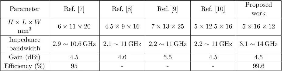
design in mid-90s. The fundamental limitations of modal analysis in antenna design was investigated by Chu in 1948 and subsequently by Harrington in 1960 while, Chu [5] postulated that, since any radiating field can be written as sum of spherical vector waves, the antenna can be enclosed in a sphere and the radiated power of the antenna is calculated from the propagating modes within the sphere and thus antenna can be considered as closed structure. A popular notion called the Characteristic Modes proposed by Garbacz corresponds with eigenvectors of a weighted eigenvalue equation and is the most common used techniques in modal analysis. With increased computational facilities and a simplified modal solution called the Theory of characteristics Modes (TCM) proposed by Harrington and Mautz in 1971, characteristic modes can be computed numerically for conducting bodies of any arbitrary shape [6]. In this communication, a systematic design approach based on the modal analysis for analysis of planar UWB monopole antenna for wireless USB dongle application is presented. A comparative study of proposed work with existing literatures is illustrated in Table 1.
Table 1. Comparison of proposed antenna with existing literatures.
Parameter Ref. [7] Ref. [8] Ref. [9] Ref. [10] Proposed work
H×L×W
mm3 6×11×20 4.5×9×16 7×13×25 5×12.5×16 5×16×12 Impedance
bandwidth 2.9∼10.6 GHz 2.1∼11 GHz 2.2∼11 GHz 2.2∼11 GHz 3.1∼14 GHz
Gain (dBi) 4.5 4.6 5.5 4.5 4.5
Efficiency (%) 95 - - - 99.6
2. MATHEMATICAL FORMULATION OF CHARACTERISTIC MODES
The current J on the surface S of a conducting body with the tangential incident dielectric field Ei is given by:
[L(J)−Ei]tan = 0 (1)
where the subscript tan denotes the tangential components on the surfaceS. Physically, the termL(J) gives the electric intensity E at any point in space due to the current J on the surface S while the impressed electric fieldEi is negative to the tangential component ofE over the surfaceS. This means that the operator Lin Equation (1) has the dimension of impedance and can be represented as:
Z(J) = [L(J)]tan (2)
where the impedance operator (Z) is complex symmetrical operator given as:
Z(J) =R(J) +jX(J) (3)
Based on the approach defined by Garbacz [11], the characteristic current modes can be obtained as the eigen functions of a particular weighted eigenvalue equation given as:
X(Jn) =λnR(Jn) (4)
where λn are the eigenvalues, Jn are the eigenfunctions or characteristic modes and R and X are the
hermitian parts (real and imaginary respectively) parts of the impedance operatorZ. The characteristic modesJn defined as a set of orthogonal real currents on surface of a conducting body depends on only
the its shape and size and are independent of any source or excitation. The electric fields En and the
magnetic fields Hn produced by an eigencurrents Jn on the surface of a conducting bodyS are called
the characteristic fields or the eigenfields [12] corresponding toJn. The orthogonal relationship between
theorem as:
P = Jm∗, ZJn=Jm∗, RJn+jJm∗, XJn (5)
PJm, Jn =
S − →
Em×−→H∗nds+jω
τ
μ−→Hm−→H∗n−−→Em−→E∗n
dτ = (1 +jλn)δmn (6)
The modal excitation coefficient, Vni, accounts for the way the position, magnitude and phase of the applied excitation influence the contribution of each mode to the total currentJ and is given by
J =
n
VniJn
1 +jλn (7)
Consequently, the productVniJnin Equation (7) models the coupling between the excitation and thenth
mode, and it determines if a particular mode is excited by the antenna feed or incident field. However, the total current in Equation (7) also depends onλn, the eigenvalue associated to thenth characteristic
current mode. Eigenvalues are of utmost importance because its magnitude gives information about the resonance frequency and radiating properties of the different current modes.
3. ANTENNA DESIGN
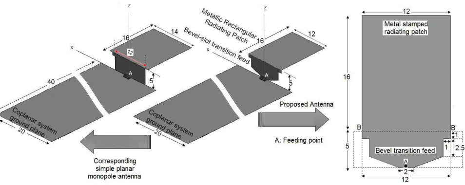
Figure 1 depicts the geometry and configuration of the simple and proposed planar monopole antenna. The simple planar monopole antenna contains two metallic rectangular radiating plates of dimensions 14×16 mm2 and 12×5 mm2 placed orthogonally on the coplanar system ground plane of dimensions 20×40 mm2 and is excited using an edge port. The proposed antenna has a bevel-slot transition feed and radiating patch of dimensions 12×16×5 mm3 mounted on a coplanar system ground plane. The compact antenna structure makes the antenna a suitable candidate for practical wireless UWB-USB dongle applications. Foremost, the modal analysis of corresponding simple planar monopole antenna is carried out by means of Theory of Characteristic Modes to get the physical insights in the different radiating modes of the arbitrary shaped antenna geometry. Based on the physical interpretation of the characteristic modes the antenna shape is modified to get the desired radiation characteristics using following four step procedure:
1 Firstly, characteristic currents and associated characteristics fields of the radiating element are calculated.
2 Next, the resonance frequency of these modes, as well as their radiating behaviour is determined from the information provided by the corresponding eigenvalues.
3 Then, the shape and size of the radiating element is modified until the desired resonance frequency and/or the radiation characteristics are achieved.
4 Finally, studying the current distribution of modes an optimum feed configuration to excite these modes is chosen to obtain a specific radiating behaviour.
3.1. Modal Analysis of Simple Planar Monopole and Its Physical Interpretation
Here, the Characteristic Mode (CM) analysis is carried out using CADFEKO 7.0 simulation software. The magnitude of the eigenvalues λn given in Equation (4) is related to the radiation of a mode
which can be best analysed by the complex power balance yielded from orthogonal relationship between characteristic field and characteristic current ruled by the Poynting theorem in Equation (6). In general, the eigenvalues range from−∞to +∞ with a mode being at resonance when it’s associated eigenvalue is zero. Moreover, it is evident that, smaller the magnitude of eigenvalues is, the more efficiently the mode radiates when excited. Additionally, the eigenvalues relate to the impedance matrix (Z) which is dependent on its hermitian parts (R and X). Thus, based on the sign of the hermitian operator X. i.e., +Xi/−Xi, the sign of eigenvalues will determine whether a mode contributes to store magnetic energy (λn>0) or electric energy (λn<0).
Nevertheless, alternative representation of eigenvalue in terms of modal significance and characteristic angle can be effective. The term modal significance (M Sn) represents the normalized
amplitude of the current modes [12]. This normalized amplitude of the current modes depends upon the shape and size of the conducting metallic body and does not account for any excitation and is given by equation:
M Sn= 1
1 +jλn
(8)
The modal expansion of the current described in Equation (8) is inversely dependent upon the eigenvalues and hence it seems more logical to analyse the variation of the term rather than to analyse the variation of the isolated eigenvalue. Characteristic angle models the phase difference between a characteristic current Jn and the associated characteristic fieldEndefined as:
αn= 180◦−tan−1(λn) (9)
Thus, a mode stores inductive energy whenαn remains close to 90◦ and stores capacitive energy when
αn is close to 270◦ while provides good radiation αn is close to 180◦.
Figure 2(e) depicts the current distribution of the first six characteristic modesJn associated to the
simple planar monopole antenna. The antenna is excited using plane waves for modal analysis. Modes
J1 andJ2 are characterized by the vertical and horizontal currents respectively and are most frequently
used modes in patch antenna applications while higher order modes J1∗, J2∗ and J1∗∗ are taken into
consideration at higher frequencies. ModeJ3presents a current forming closed loop over the rectangular
plate. Degenerated modes J1∗ and J1∗∗, characterize the same vertical current as mode J1, except
they have different current sources and current nulls while mode J2∗ is degenerated horizontal current
mode with characteristics same as mode J2 [13]. Figure 2(b) presents the variation of characteristic
angle αn with frequency associated to current modes of simple planar monopole antenna. As stated earlier, a mode is said to be at resonance when its associated eigenvalue λn= 0 or characteristic angle
αn = 180◦. As observed from Figures 2(a)–(b), modes J1 resonates at 1.8 GHz while stores inductive
energy over other frequencies after achieving resonance. Mode J2 resonates at 8.9 GHz while mode J3 that forms a closed loop current is a special non resonant mode with inductive contribution over
the operational frequencies. Degenerated vertical current modes J1∗ and J1∗∗ resonate at 3.5 GHz and
5.6 GHz respectively and remain close to αn = 180◦ after resonance. The modal excitation coefficient
determines if a particular mode is excited by an optimum feeding configuration. Figure 2(d) shows the variation of modal weighting coefficient with frequency associated to the current modes of the simple planar monopole antenna. As depicted from Figure 2(d), only three modes, namely the vertical current modeJ1and its degenerated vertical higher order modesJ1∗andJ1∗∗are excited upon using the optimum
feed configuration. ModeJ1 dominates at lower edge frequency and has significant ascendency over the
entire frequency range while higher order modes J1∗ and J1∗∗ have significant contribution over higher
(c)
(e)
(a) (b)
(f)
(g)
Figure 2. Modal solution of simple planar monopole antenna of the first six characteristic modes. (a) Variation of eigenvalues λn, (b) variation of characteristic angle αn, (c) variation of modal significance
M Sn, (d) variation of modal excitation coefficient Vni, (e) current distribution of the associated characteristic modes, (f) contribution of Modal Admittance Yn to the total input admittance Yin, (g) contribution of VSWR of the modes to the total VSWR.
modeJ3 does not achieve resonance over the desired frequency range while the fields produced by the
horizontal current modes J2 and J2∗ principally remain confined between the antenna and the system
ground plane since the separation gap between the radiating patch and the ground plane is electrically small with respect to the operating wavelength of the antenna under consideration [14]. In order to determine how much a mode contributes to the total radiating bandwidth, the input admittance of the antenna is studied. For a voltage excitation of 1V, the input admittance of the antennaYin is equal to the currentJ sampled at feed point A of the antenna is given as:
Yin = J(P) 1V =
n
VniJn(P)
1 +λn (10)
Similarly, the complex input admittance (Yin) can be expressed as sum of complex Eigen admittances, or modal admittances (Yn) as follows:
Yin=
n Yn=
n
Gn+jBn=
n
Vni·Jn(P) 1 +λ2
n −j
Vni·Jn(P)·λn
1 +λ2
n (11)
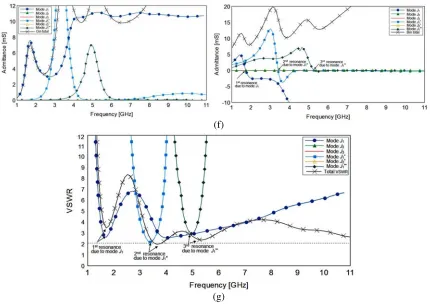
Figure 2(f) shows the contribution of Modal Admittance Yn of modes to the total input admittance
Yin. As observed from Figure 2(f) only modes J1∗, J2∗ and J1∗∗ contribute to the real part of the input
admittance, and hence towards the radiation. The rest modes yet excited do not radiate and store energy. An examination of imaginary part of the input admittance shows that mode J1 dominates at
is due to mode J1∗ (point B
) and resonance at 5.5 GHz is due to mode J1∗∗ (point C
). Figure 2(g) shows the contribution of VSWR of the modes to the total VSWR and the conclusions carried out can be endorsed. As stated earlier, the total VSWR has resonances at 1.8 GHz, 3.5 GHz and 5.5 GHz due to interaction of modeJ1 (point A),J1∗ (point B) andJ1∗∗(point C) respectively.
3.2. Design of Planar UWB Monopole Antenna
As stated earlier, mode J1 dominates the radiation characteristic over the entire frequency band
and mainly stores inductive energy after achieving resonance. To achieve the desired radiation characteristics, the shape and size of the simple planar monopole antenna needs to be modified. Furthermore, to nullify the inductive effect of mode J1 an equivalent capacitive loaded structure in
the form of bevel slot transition feed have been used for optimization of the proposed UWB planar monopole antenna. Figure 3(a) shows the variation of characteristic angle with frequency associated to the characteristic modes of the proposed antenna. As depicted in Figure 3(a), the dominant vertical mode of the proposed antenna upon achieving resonance stays close to the characteristic angleαn= 180◦
thereby nullifying the inductive storing effect. This is because the bevel transition feed acts as a variable capacitor with air as a dielectric sandwiched between metal feed on one side and metal system ground plane on the other side. Moreover, the bevel feed has altered the separation gap between the antenna and
(a) (b)
Figure 3. Modal solution of the proposed antenna. (a) Variation of characteristic angle αn with
frequency and (b) contribution of modal VSWR to the total VSWR.
(a) (b)
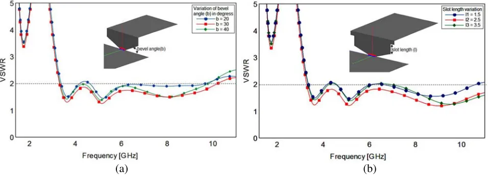
Figure 4. Parametric investigation of (a) variation of bevel angle-b and (b) variation of slot length-l
system ground plane which in return has altered the behaviour of horizontal current modes modeJ2 and J2∗ thus improving their contribution towards radiation. It is noteworthy mentioning that the current
distribution associated to the proposed antenna has not significantly altered and hence not mentioned herewith. Figure 3(b) shows the contribution of modal VSWR of the associated characteristic modes to the total VSWR. However, the total VSWR at any desired frequency is dependent on the contribution of the individual modal VSWR of all the modes. The bevel transition feed allows the upper and lower limit of the bandwidth to be modified by changing the bevel cut and antennas bandwidth ratio can change between the upper and lower limits of 1.33:1 (VSWR<2) for the initial simple planar monopole, to 3.66:1 for the proposed antenna design. The slot in the feeding structure lengthens the current path along the perimeter and has great influence on the impedance matching at the higher edge frequency. In fact, the slots are critical for the implementing the wideband operation of the proposed antenna. Figures 4(a)–(b) investigates the variation of bevel angle (b) and slot length (l) on the impedance bandwidth. Figure 5 depicts the VSWR at different stages during evolution of the proposed antenna along with the CAD prototype of the proposed antenna. The proposed antenna is then designed on a FR4 substrate with dielectric constant r = 4.4, tanδ = 0.02 and thickness 1.6 mm. Since there is
no ground plane below the radiating antenna structure, the dielectric substrate properties would not significantly alter the performance of the proposed antenna.
Figure 5. VSWR at different stages during evolution of the proposed antenna.
Figure 6. CAD and fabricated prototype of the proposed antenna along with measured results.
4. RESULTS AND DISCUSSIONS
Figure 7. Measured gain and simulated efficiency of the proposed antenna.
(a) (b) (c)
Figure 8. Simulated and measured radiation pattern along E-plane and H-plane at sampling frequencies of (a) 3.1 GHz, (b) 5.5 GHz and (c) 8.5 GHz respectively.
5. CONCLUSIONS
The bevel angle in the feed allows the upper and lower limit of the bandwidth to be modified by changing the angle of cut while slot in feed increases the current path along the perimeter which improves impedance matching over the upper edge frequencies. The simple and compact geometrical configuration with excellent wide impedance bandwidth makes the proposed antenna a suitable candidate for wireless USB dongle applications.
ACKNOWLEDGMENT
The authors would like to thank Dr. Mahesh P. Abegaonkar, Professor, Centre for Applied Research in Electronics, IIT Delhi for his assistance in antenna measurements* and Mr. Danie Ludick, Electronics Engineer, Altair Engineering, Cape Town, South Africa for this technical assistance.
REFERENCES
1. Labade, R., S. Deosarkar, and N. Pishoroty, “A novel integrated bluetooth dual band UWB antenna for wireless communication,”International Journal of Microwave and Optical Technology, Vol. 10, No. 3, 195–201, 2015.
2. Labade, R., S. B. Deosarkar, and N. Pishoroty, “Design and implementation of an integrated bluetooth ultrawideband monopole antenna,” Australian Journal of Basic and Applied Sciences, Vol. 15, No. 8, 60–66, 2014.
3. Federal Communications Commission, “Revision of Part 15 of the commissions rules regarding ultrawideband transmission systems,” First Note and Order, ET-Docket 98-153, Washington, DC, 2002.
4. Fabrs, M. C., “Systematic design of antennas using the theory of characteristic modes,” Ph.D. Dissertation, Feb. 2007.
5. Chu, L. J., “Physical limitations of omni-directional antenna,”Journal of Applied Physics, Vol. 19, 1163–1175, Dec. 1948.
6. Harrington, R. F. and J. R. Mautz, “Computation of characteristic modes for conducting bodies,”
IEEE Transactions on Antennas and Propagation, Vol. 19, No. 5, 629–639, Sep. 1971.
7. Su, S.-W.(Stephen), J.-H. Chou, and K.-L. Wong, “Internal ultrawideband monopole antenna for wireless USB dongle applications,” IEEE Transactions on Antennas and Propagation, Vol. 55, No. 4, Apr. 2007.
8. Lee, J., S. Hong, J. Shin, and J. Choi, “Compact ultra wideband monopole antenna for wireless communication application,” IEEE Transactions on Antennas and Propagation, Vol. 57, No. 9, Sep. 2009.
9. Tu, S., Y.-C. Jiao, Z. Zhang, Y. Song, and S.-M. Ning, “Small internal 2.4-GHz/UWB antenna for wireless dongle applications,” IEEE Antennas and Wireless Propagation Letters, Vol. 9, 2010. 10. Gong, J.-G., Y.-C. Jiao, Q. Li, Y. Song, and J. Wang, “Compact internal wideband antenna for
wireless USB dongle application,”IEEE Antennas and Wireless Propagation Letters, Vol. 9, 2010. 11. Garbacz, R. J., “A generalized expansion for radiated and scattered fields,” Ph.D. Dissertation,
Ohio State University, Columbus, 1968.
12. Harrington, R. F. and J. R. Mautz, “Theory of characteristic modes for conducting bodies,”IEEE Transaction on Antennas and Propagation, Vol. 19, 348–358, 1971.
13. Tambe, A. and R. P. Labade, “A novel design approach for multimode multiband MIMO antenna using modal analysis,” The 11th India IEEE Conference, INDICON, 1–5, 2014.