CHARACTERISTICS OF GUIDED MODES IN PLANAR CHIRAL NIHILITY META-MATERIAL WAVEGUIDES
J. Dong and C. Xu
Institute of Optical Fiber Communication and Network Technology Ningbo University
Ningbo 315211, China
Abstract—The characteristics of guided modes in the planar waveguides which the core or cladding consists of chiral nihility meta-materials are studied theoretically. The dispersion curves, electromagnetic fields, energy flow distribution and the power of several low-order guided modes in the chiral nihility waveguides are presented. Some novel features such as anomalous dispersion curves, the power flows opposite to the wave vector propagation direction in the chiral nihility waveguides have been found.
1. INTRODUCTION
Studies on the propagation of electromagnetic waves in waveguides are important for device design. Recently, the negative refractive index materials (NIMs) have attracted much attention because NIM has many novel features and potential applications such as perfect lens. Various waveguides including NIM have been investigated intensively [1–11]. Many novel characteristics of guided waves in NIM waveguides were found. Guided modes in a slab of uniaxial backward-wave medium can carry energy in opposite directions inside and outside the slab with backward waves inside the slab [1]. Peculiar properties of guided waves in NIM slab waveguides include the absence of fundamental modes, mode double degeneracy, and the sign-varying energy flux [2]. Anomalous dispersion curves were revealed: Below cutoff, there is a frequency range for which there are two possible propagation coefficients [3]. There exists a sort of unique electromagnetic waves termed as “surface waves” whose electromagnetic fields exponentially decay on both sides of the
interfaces between NIM and conventional materials, and cannot exist in normal waveguides [4–6]. All surface plasmon polarition (so-called SPP) eigenmodes supported by generalized asymmetric slab heterostructures have been identified and classified [5]. Similar peculiar properties of guided modes and surface wave (SPP) are also found in the NIM grounded slab waveguides [7–9]. Waves in NIM waveguides can propagate very slowly and even can be stopped [10, 11].
On the other hand, waveguides including chiral media have been studied intensively because of their important potential applications in optics and microwaves [12–14]. More recently, the chiral medium has been suggested to achieve NIM [15–17]. It has been shown that the chirality parameter can be greater than refraction index at least near the resonant frequency, thus one eigen-wave in the chiral medium becomes a backward wave, making negative refraction in the chiral medium possible [16, 17]. The effective negative index of refraction in chiral meta-materials has been experimentally achieved at microwave frequencies [18] and THz frequencies [19] in 2009. The novel feature of guided modes in chiral negative refraction waveguides has been investigated theoretically [20–22]. Waves in the parallel-plate waveguide containing two-layer chiral nihility meta-materials (the chiral medium in which the permittivity and permeability are simultaneously zero) and one air layer [23], and in the grounded chiral nihility metamaterial slab has been examined [24].
In this paper, we firstly present the dispersion equations of general chiral planar waveguides in which both the core and cladding consist of chiral materials. Then two special cases: The planar waveguides consisting of a chiral nihility meta-material core with an achiral cladding and a chiral nihility meta-material cladding with an achiral core are examined in detail. For guided odd and even modes, the dispersion equations, normalized cutoff frequencies, electromagnetic fields, and energy flow of right-handed and left-handed circularly polarized (RCP and LCP) modes are derived in explicit forms. Numerical results of several low-order guided modes are given for typical chirality parameters. Some novel features such as anomalous dispersion curves and the power flows opposite to the wave vector propagation direction in the chiral nihility waveguides are found.
2. DISPERSION EQUATIONS OF GENERAL
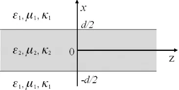
Figure 1. Geometry of the three-layered planar chiral waveguide.
adopted here for a time-harmonic field with exp(jωt) are as follows:
D=εiE−jκi√μ0ε0H, B=μiH+jκi√μ0ε0E (1)
where μi, εi, κi (i = 1,2) are permeability, permittivity and chirality
parameter, respectively.
In the chiral medium, electromagnetic fields can be expressed as [17]:
E=E++E−, H=H++H− (2)
The relationship between electric and magnetic fields is
H±=±j·E±/ηi (3)
whereE+ andE− are solutions of the wave equations:
(∇2+ki2+)E+= 0, (∇2+ki2−)E−= 0 (4)
where ki± = ni±k0, and ni± = ni ±κi are the effective refractive
index of the two eigen-waves (the subscription + and−correspond to right- and left-handed circularly polarized waves, respectively denoted as RCP and LCP) in the chiral media;k0 =ω√μ0ε0,ni=
μiεi/μ0ε0
andηi=
μi/εi are the wavenumber in free space, the refractive index
and wave impedance of the chiral medium. If the chirality parameter is very large (κi > ni), then the effective refractive index ni− for the LCP eigen-wave is negative (ni− < 0). We call this type of strong chiral medium as chiral negative refraction medium.
Because the planar chiral waveguide structure is symmetry to x -axis, we can express the solutions of the longitudinal-field component in Equation (4) as [14]:
Ez±=
A±sin(kx±x) |x|< d/2
for guided odd modes, and
Ez±=
A±cos(kx±x) |x|< d/2 B±exp[−γx±(|x| −d/2)] |x|> d/2
(6)
for guided even modes, where exp[j(ωt−βz)] is omitted for simplicity and β is the longitudinal propagation constant, the parameters
kx±, γx± are kx±= (k22±−β2)1/2, γx±= (β2−k12±)1/2.
The relationship between the transversal and longitudinal electromagnetic field components can be found in [12]. According to the boundary condition (continuity of the tangential fields) for electromagnetic field components atx=d/2, the dispersion equations of guided modes in the planar chiral waveguides can be derived as follows:
k1+
γx+ sinu+− k2+ kx+cosu+
−k1−
γx−sinu−+
k2−
kx−cosu−
(η1+η2)2
+
k1−
γx−sinu++
k2+ kx+cosu+
k1+
γx+ sinu−+ k2−
kx−cosu−
(η1−η2)2= 0
(7)
for guided odd modes, and
k1+
γx+cosu++ k2+ kx+ sinu+
k1−
γx−cosu−+
k2−
kx−sinu−
(η1+η2)2
+
k1−
γx−cosu+−
k2+ kx+ sinu+
−k1+
γx+cosu−+ k2−
kx−sinu−
(η1−η2)2= 0
(8)
for guided even modes, where u± = kx±d/2. These dispersion
equations are consistent with whose in [14]. However, the constitutive relations adopted here are different, and there were many typo mistakes in dispersion relation formula in [14].
In the next sections, we will focus on the two special cases: The planar waveguides consisting of a chiral nihility core with an achiral cladding and a chiral nihility cladding with an achiral core. The chiral nihility meansμi = 0, εi= 0, κi = 0.
3. GUIDED MODES IN PLANAR CHIRAL NIHILITY CORE WAVEGUIDES
When the core is a chiral nihility meta-material and cladding is an achiral medium, the above parameters become k2± = ±κ2k0, kx± =
(k22± − β2)1/2 = (κ22k02 − β2)1/2 = kx, γx± = (β2 − k12±)1/2 =
(β2 −k12)1/2 = γx, u± = kx±d/2 = kxd/2 = u. It is shown that
3.1. Odd Modes
3.1.1. Dispersion Equation
The dispersion equations are:
(κ22k02−β2)1/2 d
2= tan −1
κ2k0 k1
β2−k12 κ22k20−β2
1/2+mπ, m= 0,1,2. . . (9)
for RCP odd modes, and
(κ22k02−β2)1/2 d
2=−tan −1
κ2k0 k1
β2−k2 1 κ22k02−β2
1/2+mπ, m= 1,2,3. . . (10)
for LCP odd modes, where m is mode number. It is noted that m
starts from 0 for RCP odd modes and from 1 for LCP odd modes.
3.1.2. Normalized Cutoff Frequency
The normalized cutoff frequencies can be obtained from the dispersion Equations (9) and (10) by settingβ →k1:
(k0d)c =
2mπ
(κ2
2−n21)1/2
, m= 0,1,2. . . (11)
for RCP odd modes, and
(k0d)c =
2mπ
(κ22−n21)1/2
, m= 1,2,3. . . (12)
for LCP odd modes.
3.1.3. Electromagnetic Field
The electromagnetic fields can be derived directly in explicit forms; here onlyx >0 region are presented; andx <0 region can be obtained according to symmetry.
In the corex < d/2, the electric fields for both RCP and LCP odd modes are: ⎧ ⎪ ⎪ ⎪ ⎪ ⎪ ⎪ ⎨ ⎪ ⎪ ⎪ ⎪ ⎪ ⎪ ⎩
Ex=−jβ
kx C
sin(u)cos(kxx)
Ey =−κ2k0
kx C
sin(u)cos(kxx)
Ez = C
sin(u)sin(kxx)
In the claddingx > d/2, the electric fields are: ⎧
⎪ ⎪ ⎪ ⎪ ⎨ ⎪ ⎪ ⎪ ⎪ ⎩
Ex=−jβ γxCe
−γx(x−d/2)
Ey =∓k1 γxCe
−γx(x−d/2)
Ez =Ce−γx(x−d/2)
(14)
for RCP (upper sign) and LCP (lower sign) odd modes, respectively where C is an arbitrary constant, which can be determined by total power.
The magnetic fields in the core and cladding are: H
x Hy Hz
=± j
η1
E
x Ey Ez
(15)
for RCP (upper sign) and LCP (lower sign) odd modes, respectively.
3.1.4. Energy Flow
Energy flow along thez-axis in the waveguides is defined by
Sz = 1
2Re(E×H
∗)·ˆz= 1
2Re(ExH ∗
y−EyHx∗) (16)
In the corex < d/2, energy flow is:
Sz=±βκ2k0
η1k2x
sin(Cu)2cos2(kxx) (17)
for RCP (upper sign) and LCP (lower sign) odd modes, respectively. In the claddingx > d/2, energy flow is:
Sz= ηβk1 1γx2|C|
2
e−2γx(x−d/2) (18)
for both RCP and LCP odd modes.
It is obvious from formulas (17), (18) thatSz is positive for RCP
3.2. Even Mode
3.2.1. Dispersion Equation
The dispersion equations are:
(κ22k02−β2)1/2 d
2=−tan −1
k1 κ2k0
κ22k02−β2 β2−k2
1
1/2 +
mπ, m= 1,2,3. . . (19)
for RCP even modes, and
(κ22k02−β2)1/2 d
2= tan −1
k1 κ2k0
κ22k02−β2 β2−k2
1
1/2 +
mπ, m= 0,1,2. . . (20)
for LCP even modes.
It is noted that, in contrast to odd modes, m starts from 1 for RCP even modes and starts from 0 for LCP even modes.
3.2.2. Normalized Cutoff Frequency
The normalized cutoff frequencies can be obtained from the dispersion Equations (19) and (20) by settingβ →k1:
(k0d)c =
(2m−1)π
(κ2
2−n21)1/2
, m= 1,2,3. . . (21)
for RCP even modes, and
(k0d)c =
(2m+ 1)π
(κ2
2−n21)1/2
, m= 0,1,2. . . (22)
for LCP even modes.
3.2.3. Electromagnetic Field
In the core x < d/2, the electric fields for both RCP and LCP even modes are: ⎧ ⎪ ⎪ ⎪ ⎪ ⎪ ⎨ ⎪ ⎪ ⎪ ⎪ ⎪ ⎩
Ex = jβk x
C
cos(u)sin(kxx),
Ey = κ2k0
kx C
cos(u)sin(kxx),
Ez = cos(Cu)cos(kxx)
(23)
The relationship between magnetic and electric fields in the core and cladding is also the same as that for RCP and LCP odd modes (see Equation (15)).
3.2.4. Energy Flow
In the corex < d/2, energy flow is:
Sz=±βκη 2k0 1k2x
cos(Cu)2sin2(kxx) (24)
for RCP (upper sign) and LCP (lower sign) odd modes, respectively. In the claddingx > d/2, the formulas of energy flow are the same as those for RCP and LCP odd modes (see Equation (18)).
3.3. Numerical Example
The propagation constants can be calculated numerically from the dispersion equations (9), (10), (19), (20), then the electromagnetic fields and the energy flow distribution can be obtained. The normalized total power can be expressed as [2]
P = P1+P2
|P1|+|P2|
(25)
where P1 = 2
∞
d/2Szdx and P2 =
d/2
−d/2Szdx are the power in the
cladding and core, respectively. In this section, we present typical numerical results for the parameters in the core and cladding being
μ2=ε2 = 0, κ2 = 1.5 andμ1 =μ0, ε1=ε0, κ1 = 0.
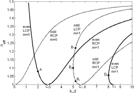
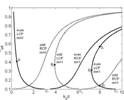
Figure 2 shows the dispersion curves of several low-order guided odd and even modes in the planar chiral nihility core waveguide, where neff = β/k0 is the effective refractive index; k0d is the
normalized frequency. Dashed and solid curves correspond to the odd and even modes, respectively. For RCP odd and even modes, the curves of effective refractive index versus normalized frequency increases monotonically, and the normalized cutoff frequencies (points
C1, C2, when neff = 1) satisfy Equation (11) or (21). However, for
LCP odd and even modes, dispersion curves are no longer increasing monotonically, but are bent, and the cutoff frequencies (whenneff = 1)
are not the minimum frequencies that waves can propagate. When
m= 0, there is one solution below cutoff frequency (pointC1) for LCP
even mode in some frequency region. When m = 1, there are two solutions below cutoff frequencies (points C2, C3) for both LCP even
Figure 2. Dispersion curves of guided modes in the planar chiral nihility core waveguide.
here are not really “cutoff”. The real “cutoff” frequencies correspond to the minimum frequencies (critical points B0, D0) that guided wave
can propagate. As the normalized frequency increases from the critical points B0, D0, dispersion curves bifurcate two branches, which the
effective refractive index increases for upper branch and decreases to
neff = 1 for lower branch.
Figures 3 and 4 show the amplitudes of electromagnetic field components and energy flux distribution at normalized frequency
k0d= 2 (pointAin Fig. 2) for LCP even mode whenm = 0. Ez, Hz are
even functions of x (cos form) and Ex, Ey, Hx, Hy (sin form) are odd
functions ofx. Sz is negative in the core and positive in the cladding;
the absolute power |P2| in the core is smaller than power P1 in the
cladding, thus the total power is positive.
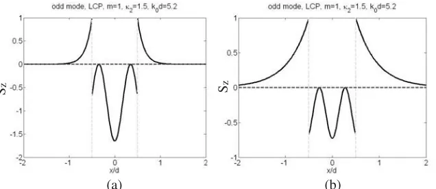
Figures 5 and 6 show the amplitude of electromagnetic field components and energy flux distribution at normalized frequency
k0d = 5.2 for LCP odd mode when m = 1. Ez, Hz are odd functions
of x(sin form) and Ex, Ey, Hx, Hy (cos form) are even functions ofx. Sz is negative in the core and positive in the cladding, too. However, there are two propagation constants at k0d= 5.2. For larger effective
Figure 3. Amplitudes of electromagnetic field components atk0d= 2
for LCP even mode when m= 0.
Figure 4. Energy flux at k0d= 2 for LCP even mode whenm= 0.
P1 in the cladding, thus the total power is negative. For smaller
effective refractive index (point B2 in lower branch dispersion curve
in Fig. 2),neff = 1.0237, the absolute power |P2|is smaller in the core
than power P1 in the cladding, thus the total power is positive.
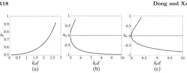
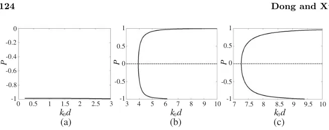
The normalized total powerP versus normalized frequencyk0dis
plotted in Fig. 7 for three LCP modes (bended dispersion curves). For LCP even mode whenm = 0, P decreases as k0ddecreases; however,
Figure 5. Amplitude of electromagnetic components at k0d= 5.2 for
LCP odd mode when m= 1, neff = 1.2224.
(a) (b) Sz
Sz
Figure 6. Energy flux at k0d= 5.2 for LCP odd mode whenm = 1,
(a)neff = 1.2224; (b) neff = 1.0237.
is always smaller than that in the cladding. For LCP odd mode when
m = 1, P is negative for upper branch dispersion curve and positive for lower branch dispersion curve. For upper branch dispersion curve, amplitude of P decreases from nearly −1 to 0 as k0d decreases from
10 to 5 (critical point B0 in Fig. 2). It implies that at critical point,
the waveguide cannot propagate energy. For lower branch dispersion curve, P increases as k0d increases from critical point B0 to cutoff
(a) (b) (c)
k d0 k d0 k d0
P P P
1
0.9
0.8
0.7
0.6
0.5
0 0.5 1 1.5 2 2.5 3
1
0.5
0
-0.5
-1
5 6 7 8 9 10
1
0.5
-0.5
-1 0
8 8.5 9 9.5 10
Figure 7. Normalized total power versus normalized frequency for (a) LCP even mode, m = 0; (b) LCP odd mode, m = 1; (c) LCP even mode,m = 1.
m= 1. It is noted that for RCP odd and even modes, the power both in the core and in the cladding are positive and the total power always positive. The reason of above results is that LCP is backward (negative refraction) wave and RCP is forward (positive refraction) wave in the chiral nihility meta-material, which means energy flow along thez-axis is negative for LCP waves and positive for RCP waves.
4. GUIDED MODES IN PLANAR CHIRAL NIHILITY CLADDING WAVEGUIDES
When the cladding is a chiral nihility meta-material and core is an achiral medium, the above parameters become kx±= (k22±−β2)1/2 =
(k22−β2)1/2 =kx, k1± =±κ1k0,γx±= (β2−k12±)1/2 = (β2−κ21k02)1/2 = γx, u± = kx±d/2 = kxd/2 = u. It is also shown that both the
dispersion Equations (7) and (8) can be divided into two equations which correspond to RCP and LCP modes, respectively. For guided odd and even modes, the dispersion equations, normalized cutoff frequencies, electromagnetic fields, and energy flow of RCP and LCP modes are also obtained as follows.
4.1. Odd Mode
4.1.1. Dispersion Equation
The dispersion equation is
(k22−β2)1/2 d
2= tan −1
k2 κ1k0
β2−κ21k02 k22−β2
for RCP odd modes, and
(k22−β2)1/2 d
2=−tan −1
k2 κ1k0
β2−κ21k02 k2
2−β2
1/2 +
mπ, m= 1,2,3. . . (27)
for LCP odd modes, wherem is mode number.
4.1.2. Normalized Cutoff Frequency
The normalized cutoff frequencies can be obtained from the dispersion Equations (26) and (27) by settingβ →κ1k0:
(k0d)c =
2mπ
(n2
2−κ21)1/2
, m= 0,1,2. . . (28)
for RCP odd modes, and
(k0d)c =
2mπ
(n22−κ21)1/2
, m= 1,2,3. . . (29)
for LCP odd modes.
4.1.3. Electromagnetic Field
In the corex < d/2, the electric fields are: ⎧ ⎪ ⎪ ⎪ ⎪ ⎨ ⎪ ⎪ ⎪ ⎪ ⎩
Ex=−jβ
kxAcos(kxx)
Ey =∓k 2 kxA
cos(kxx)
Ez=Asin(kxx)
(30)
for RCP (upper sign) and LCP (lower sign) odd modes, respectively. In the claddingx > d/2, the electric fields for both RCP and LCP odd modes are:
⎧ ⎪ ⎪ ⎪ ⎪ ⎨ ⎪ ⎪ ⎪ ⎪ ⎩
Ex=−jβγ xA
sin(u)e−γx(x−d/2)
Ey =−κ1k0
γx Asin(u)e
−γx(x−d/2)
Ez =Asin(u)e−γx(x−d/2)
(31)
The magnetic fields in the core and cladding are:
Hx Hy Hz
=± j
η2
Ex Ey Ez
(32)
for RCP (upper sign) and LCP (lower sign) odd modes, respectively.
4.1.4. Energy Flow
In the corex < d/2, energy flow is:
Sz = βk 2 η2k2x|A|
2cos2(
kxx) (33)
for both RCP and LCP odd modes.
In the claddingx > d/2, energy flow is:
Sz=±βκ1k0
η2γx2 |A| 2sin2(
u)e−2γx(x−d/2) (34)
for RCP (upper sign) and LCP (lower sign) odd modes, respectively. It is obvious from formulas (33), (34) thatSz is positive for both RCP and LCP modes in the core, and positive for RCP odd modes and negative for LCP odd modes in the cladding. It also indicates that energy flow of LCP modes is in opposite directions in the core and cladding.
4.2. Even Mode
4.2.1. Dispersion Equation
The dispersion equations are:
(k22−β2)1/2 d
2=−tan −1
κ1k0 k2
k22−β2 β2−κ2
1k02
1/2 +
mπ, m= 1,2,3. . . (35)
for RCP even modes, and
(k22−β2)1/2 d
2= tan −1
κ1k0 k2
k22−β2 β2−κ2
1k02
1/2 +
mπ, m= 0,1,2. . . (36)
4.2.2. Normalized Cutoff Frequency
The normalized cutoff frequencies can be obtained from the dispersion Equations (35) and (36) by settingβ →κ1k0:
(k0d)c =
(2m−1)π
(n22−κ21)1/2
, m= 1,2,3. . . (37)
for RCP even modes, and
(k0d)c =
(2m+ 1)π
(n22−κ21)1/2
, m= 0,1,2. . . (38)
for LCP even modes.
4.2.3. Electromagnetic Field
In the corex < d/2, the electric fields are: ⎧
⎪ ⎪ ⎪ ⎪ ⎨ ⎪ ⎪ ⎪ ⎪ ⎩
Ex= jβ
kxAsin(kxx)
Ey =±k2
kxA
sin(kxx)
Ez=Acos(kxx)
(39)
for RCP (upper sign) and LCP (lower sign) even modes, respectively. In the claddingx > d/2, the electric fields for both RCP and LCP even modes are:
⎧ ⎪ ⎪ ⎪ ⎪ ⎨ ⎪ ⎪ ⎪ ⎪ ⎩
Ex=−jβγ xA
cos(u)e−γx(x−d/2)
Ey =−κγ1k0 x A
cos(u)e−γx(x−d/2)
Ez =Acos(u)e−γx(x−d/2)
(40)
The relationship between magnetic and electric fields in the core and cladding are also the same as those for RCP and LCP odd modes (see Equation (32)).
4.2.4. Energy Flow
In the corex < d/2, energy flow is:
Sz = βk2
η2k2x|A| 2sin2(
Figure 8. Dispersion curves of guided modes in the planar chiral nihility cladding waveguide.
for both RCP and LCP even modes.
In the claddingx > d/2, energy flow is:
Sz=±βκ1k0
η2γx2 |A| 2cos2(
u)e−2γx(x−d/2) (42)
for RCP (upper sign) and LCP (lower sign) even modes, respectively.
4.3. Numerical Example
In this section, we present typical numerical results for the parameters in the core and cladding being μ2 = μ0, ε2 = ε0, κ2 = 0 and μ1 =ε1 = 0, κ1 = 0.1. In contrast to Section 3.3, here the chirality
parameter is smaller. This is an air-layer-open waveguide with chiral nihility meta-material cladding and is different from the structure in reference [23].
Figure 8 displays the dispersion curves of several low-order guided odd and even modes in the planar chiral nihility cladding waveguide. Dashed and solid curves correspond to the odd and even modes, respectively. The characteristics of dispersion curves are also anomalous and similar as Fig. 2 in Section 3.3.
The energy flux distribution at normalized frequency k0d = 0.5
(point A in dispersion curves in Fig. 8) for LCP even mode when
m = 0 is shown in Fig. 9. Sz is positive in the core and negative in the cladding; the power P2 in the core is much smaller than absolute
Figure 9. Energy flux at k0d= 0.5 for LCP even mode when m= 0.
(b) (a)
Sz Sz
Figure 10. Energy flux at k0d= 8 for LCP even mode when m= 1,
(a)neff = 0.5698; (b) neff = 0.1360.
Figure 10 shows the energy flux distribution at normalized frequency k0d = 8 for LCP even mode when m = 1. Sz is positive
in the core and negative in the cladding, too. For larger effective refractive index (pointD1 in upper branch dispersion curve in Fig. 8) neff = 0.5698, the power P2 is larger in the core than absolute power
|P1| in the cladding, thus the total power is positive. For smaller
effective refractive index (pointD2 in lower branch dispersion curve in
Fig. 8),neff = 0.1360, the powerP2is smaller in the core than absolute
0
-0.2
-0.4
-0.6
-1
0 0.5
-0.8
1 1.5 2 2.5 3
k d0
P
(a) (b) (c)
1
0.5
0
-0.5
-1
P
3 4 5 6 7 8 9 10
k d0
1
0.5
0
-0.5
-1
P
7 7.5 8 8.5 9 9.5 10
k d0
Figure 11. Total power versus normalized frequency for (a) LCP even mode,m= 0; (b) LCP odd mode,m= 1; (c) LCP even mode,m= 1.
The normalized total powerP versus normalized frequencyk0dis
plotted in Fig. 11 for three LCP modes (bended dispersion curves). For LCP even mode whenm= 0,P is always near−1 ask0ddecreases. It
indicates that the power P2 in the core is much smaller than absolute
power|P1|in the cladding. For LCP odd and even modes whenm= 1,
the results is similar to those in Section 3.3; however, the positive and negative are reversed.
5. CONCLUSION
The dispersion equations of general chiral planar waveguides in which both the core and cladding are chiral materials are presented. Guided modes in two special cases: Planar chiral nihility core or cladding waveguides are examined in detail. It has been shown that for guided odd and even modes in the chiral nihility waveguides, both the dispersion equations can be divided into two equations which correspond to RCP and LCP modes, respectively. For guided odd and even modes, the dispersion equations, normalized cutoff frequencies, electromagnetic fields, and energy flow of RCP and LCP modes are derived in explicit forms. Numerical results of several low-order guided modes are given for typical chirality parameters. Some novel features such as anomalous dispersion curves and the power flows opposite to the wave vector propagation direction in the chiral nihility waveguides have been found.
ACKNOWLEDGMENT
China (Grant No. 60777037) and is partially sponsored by K.C.Wong Magna Fund in Ningbo University.
REFERENCES
1. Lindell, I. V. and S. Ilvonen, “Waves in a slab of uniaxial BW medium,” Journal of Electromagnetic Waves and Applications, Vol. 16, No. 3, 303–318, 2002.
2. Shadrivov, I. V., A. A. Sukhorukov, and Y. S. Kivshar, “Guided modes in negative-refractive-index waveguides,” Phys. Rev. E, Vol. 67, 057602, 2003.
3. Cory, H. and A. Barger, “Surface-wave propagation along a metamaterial slab,”Microwave Opt. Technol. Lett., Vol. 38, No. 5, 392–395, 2003.
4. Wu, B.-I., T. M. Grzegorczyk, Y. Zhang, and J. A. Kong, “Guided modes with imaginary transverse wave number in a slab waveguide with negative permittivity and permeability,” J. Appl. Phy., Vol. 93, No. 11, 9386–9388, 2003.
5. Tsakmakidis, K. L., C. Hermann, A. Klaedtke, C. Jamois, and O. Hess, “Surface plasmon polaritons in generalized slab heterostructures with negative permittivity and permeability,”
Phys. Rev. B, Vol. 73, 085104, 2006.
6. Wang, Z.-J. and J. Dong, “Analysis of guided modes in asym-metric left-handed slab waveguides,”Progress In Electromagnetics Research, PIER 62, 203–215, 2006.
7. Mahmoud, S. F. and A. J. Viitanen, “Surface wave character on a slab of metamaterial with negative permittivity and permeability,”
Progress In Electromagnetics Research, PIER 51, 127–137, 2005. 8. Li, C., Q. Sui, and F. Li, “Complex guided wave solution of
grounded dielectric slab made of metamaterials,” Progress In Electromagnetics Research, PIER 51, 187–195, 2005.
9. Shu, W. and J.-M. Song, “Complete mode spectrum of a grounded dielectric slab with double negative metamaterials,” Progress In Electromagnetics Research, PIER 65, 103–123, 2006.
10. Tsakmakidis, K. L., A. D. Boardman, and O. Hess, “Trapped rainbow’ storage of light in metamaterials,”Nature, Vol. 450, 397– 401, 2007.
11. Jiang, T., J. Zhao, and Y. Feng, “Stopping light by an air waveguide with anisotropic metamaterial cladding,”Opt. Express, Vol. 17, 170–177, 2009.
and fields for a chiral slab waveguide,” IEE Proc. H Microwave Ant. Prop., Vol. 138, 327–334, 1991.
13. Mariotte, F., P. Pelet, and N. Engheta, “A review of recent study of guided waves in chiral media,” Progress In Electromagnetics Research, PIER 09, 311–350, 1994.
14. Flood, K. M. and D. L. Jaggard, “Single-mode operation in symmetric planar waveguides using isotropic chiral media,” Opt. Lett., Vol. 21, No. 7, 474–476, 1996.
15. Tretyakov, S., I. Nefedov, A. Sihvola, S. Maslovski, and C. Simovski, “Waves and energy in chiral nihility,” Journal of Electromagnetic Waves and Applications, Vol. 17, 695–706, 2003. 16. Pendry, J. B., “A chiral route to negative refraction,” Science,
Vol. 306, 1353–1355, 2004.
17. Tretyakov, S., A. Sihvola, and L. Jylh¨a, “Backward-wave regime and negative refraction in chiral composites,” Photonics and Nanostructures, Vol. 3, 107–115, 2005.
18. Plum, E., J. Zhou, J. Dong, V. A. Fedotov, T. Koschny, C. M. Soukoulis, and N. I. Zheludev, “Metamaterial with negative index due to chirality,”Phys. Rev. B, Vol. 79, 035407, 2009. 19. Zhang, S., Y. Park, J. Li, X. Lu, W. Zhang, and X. Zhang,
“Negative refractive index in chiral metamaterials,” Phys. Rev. Lett., Vol. 102, 023901, 2009.
20. Jin, Y., J. He, and S. He, “Surface polaritons and slow propagation related to chiral media supporting backward waves,”Phys. Letters A, Vol. 351, 354–358, 2006.
21. Dong, J. F., Z. J. Wang, L. L. Wang, and B. Liu. “Novel char-acteristics of guided modes in chiral negative refraction waveg-uides,”Proceedings of International Symposium on Biophotonics, Nanophotonics and Metamaterials, Metamaterials 2006, 517–520, Oct. 2006.
22. Zhang, C. and T. J. Cui, “Chiral planar waveguide for guiding single-mode backward wave,” Opt. Commun., Vol. 280, No. 2, 359–363, 2007.
23. Cheng, Q., T. J. Cui, and C. Zhang, “Waves in planar waveguide containing chiral nihility metamaterial,”Opt. Commun., Vol. 276, No. 2, 317–321, 2007.