© 2015, IJCSMC All Rights Reserved 143 Available Online atwww.ijcsmc.com
International Journal of Computer Science and Mobile Computing
A Monthly Journal of Computer Science and Information Technology
ISSN 2320–088X
IJCSMC, Vol. 4, Issue. 8, August 2015, pg.143 – 165
RESEARCH ARTICLE
Amalgamation of Wireless Sensor Networks
and Embedded Systems
K. Anil Kumar, Rajashekhar Gangannavar
Assistant Professor Department of Computer Science, Visvesvaraya Technological University, India Student, Department of Computer Science, Visvesvaraya Technological University, India
[email protected] [email protected]
Abstract – Technical advancements in the computing technologies and chip design technologies, in which integration of more and more number of transistors is possible and are fabricated over a very small piece of silicon chip, lead Wireless Sensor Networks (WSN) to its new level. Many-core sensor network does its job in a better fashion with its architectural capabilities. This paper is a single step work to bring all single core sensor architecture to its maximum potential point that is to multi core environment. Wireless Sensor Networks (WSN) includes sensor nodes with embedded sensors for sensing data about where it is deployed and these nodes uses wireless links to communicate with other neighboring sensors. Many modern sensor applications requires plenty of sensors nodes for sensing data such as temperature, pressure, humidity, acoustic, image, video etc., in traditional Wireless Sensor Networks (WSN) sensed date is sent to sink node in which the entire processing is done. This scenario is not so practical for the applications such as multimedia sensors witch senses the images and videos. Transmission and also processing of sensed data in a Traditional Wireless Sensor Network (WSN) is far beyond its capabilities. Applications requiring large computations and bandwidth can be served by adopting high degree of core architecture. Processing of sensed data at the initial stage not only results in reduced power consumption at node levels also results reduced bandwidth usages. This paper gives you the idea of how modern embedded technology can contribute to technology up gradation.
Keywords— Wireless Sensor Network; VLSI; embedded system; multi core
I INTRODUCTION
© 2015, IJCSMC All Rights Reserved 144
Processing and transmission of the large amount of sensed data in emerging applications exceeds the capabilities of traditional WSGs. For example, consider a military WSG deployed in a battlefield, which requires various sensors, such as imaging, acoustic, and electromagnetic sensors. This application presents various challenges for existing WSGs since transmission of high-resolution images and video streams over bandwidth-limited wireless links from sensor nodes to the sink node is infeasible. Furthermore, meaningful processing of multimedia data (acoustic, image, and video in this example) in real-time exceeds the capabilities of traditional WSGs consisting of single-core embedded sensor nodes [1], [2], and requires more powerful embedded sensor nodes to realize this application. Hence this paper highlight this portion of the WSG.
II EXISTING SYSTENM
Currently existing sensor networks are of a single core sensor networks, which are capable of doing the tasks with only scalar values and by considering the real time application requirements we can say that the single-core WSGs will soon be unable to meet the increasing requirements of information-rich applications (e.g., video sensor networks), next generation sensor nodes must possess enhanced computation and communication capabilities. For example, the transmission rate for the first generation Mica motes was 38.4 kbps whereas the second generation Mica motes (MicaZ motes) can communicate at 250 kbps using IEEE 802.15.4 (Zigbee) [3]. Despite these advances in communication, limited wireless bandwidth from sensor nodes to the sink node makes timely transmission of multimedia data to the sink node infeasible. In traditional WSGs, the communication energy dominates the computation energy. For example, an embedded sensor node produced by Rockwell Automation [4] expends 2000 more energy for transmitting a bit than that of executing a single instruction [5]. Similarly, transmitting a 15 frames per second (FPS) digital video stream over a wireless Bluetooth link takes 400 mW [6].
Fortunately, there exists a tradeoff between transmission and computation in an WSG, which is well-suited for in-network processing for information-rich applications and allows transmission of only event descriptions (e.g., detection of a target of interest) to the sink node to conserve energy. Technological advancements in core architectures have made multi-core processors a viable and cost effective choice for increasing the computational ability of embedded sensor nodes. Multi-core embedded sensor nodes can extract the desired information from the sensed data and communicate only this processed information, which reduces the data transmission volume to the sink node. By replacing a large percentage of communication with in-network computation, multi-core embedded sensor nodes could realize large energy savings that would increase the sensor network’s overall lifetime.
A. Limitations in Existing System
1) High Voltage Requirements – When a single core sensor is used for high in network operations it drains high voltage while working at high frequencies.
2) Fulfilling RT application requirements – Since the existing system is limited to supplying required data for some scalar devices and is incapable of providing data sufficiently to real time requirements.
B. Objective of The Project
The objective of the project is to provide insight of the WSG taking from the implemented conventional sensor networks to future sensor networks. By implementing architectural change in the conventional sensor networks. That is by adopting many or multi core sensors within the network.
C. Proposed Solution and Advantages
© 2015, IJCSMC All Rights Reserved 145
multi-core embedded sensor node reduces the number of memory accesses, clock speed, and instruction decoding, thereby enabling higher arithmetic performance at a lower power consumption as compared to a single-core processor [6].
1) Advantages:
- Reduced energy consumption - Meeting the in network requirements
- Sense-Capture and send technique can be implemented
D. Organization of the project report
The arrangement of project is in the following way. Comprise of totally 8 sections, references and appendices. Section 1 gives the overall introduction. Section 2 gives info about the papers that were referred in order to accomplish this project. Gives a detailed study of the theoretical background related to the project. Part 3 examines about the framework improvement system used to do the undertaking. Section 4 gives the details of requirement analysis and system specifications needed to successfully furnish the project. Section 5 includes some basic design concept and the needful design diagrams that help in outlining the project. Section 6 describes enactment of chunks and also verbalizes about the tools and automations used for enactment. Section 7 defines unalike testing modus utilized for testing divergent chunks in the project. Section 8 accomplishes the thesis work and recaps the project. It also sights some future boost scopes of the undertaking.
III LITERATURE AUDIT
A. Theoretical Backgrounds
Now a day’s shortwave feeler field is one of the wide spreading area in which the feelers are statically deployed in the operable grid. Each and every node in the grid is given with the facilities like limited battery supply, restricted signal sensing and processing capacity, small range of communication with a small dedicated storage.
Since every node in the feeler grid is given with limited amount of processing of signal and communicating with a small restricted surroundings it can handle only a little part of entire task. If all nodes are combined and legitimate to enact major part of the entire task it is compatible to most of the work to be get it done within short span of time.
The joints are adopted in wireless grid they got the advantage of not requiring any wired connections. Thus the cost of deployment of joints in the grid has been reduced. Feeler nodes are most widely applicable in many of the ways. For instance feeler joints may be deployed in remote stations which are mainly used to monitor the life of animals. Utilizing which we can get to know the shifting of all the animals in that particular region.
Even the feeler joints are mainly applicable in transport grid for monitoring the vehicles motion also to observe the speed of the vehicles with which they are moving on the road. The joints are loaded on either interlocution of the road hence they can monitor the movement of all the vehicles passing by the road.
Sensing of the weather conditions like pressure, temperature, humidity etc can be weighed and calculated utilizing the tiny nodes. Also the prospect of fall of rain is identified by making use of feelers of the feeler field.
Initially when a node is deployed in the grid it is built with a transmitter, a receiver with an antenna provided internally or linked to an external antenna. Mightily of the time all the nodes are assembled electronic microcontroller for interfacing with other nodes.
Since the nodes preferably used in variety of environments their developing costs may vary. The part of energy they consume out of entire available may be prepense as one of factor for calculating the cost with which they can be build. Also the considerations like their capacity of processing the data and the area they are covering in which they are going to communicate can also be prepense for cost verification
The number of joints in the feeler environment differ from hundred to lakhs. Before forming the crowd of grid the feelers placed in a wide geographical area. The feelers are installed with the aim of collecting the info. Usually the permission for deploying the feelers in the pre-defined area by government or by military offices.
© 2015, IJCSMC All Rights Reserved 146
Now it is the responsibility of the head of the crowd to address the info received from its underlying nodes. Leader of cluster may ensue either one directional data transmission or may use bidirectional transmission for passing the message to the satellite or to the static BS. For any project to start, detailed background knowledge is mandatory and necessary. Literature audit focuses on details of erstwhile knowledge and researches. These researches have help to attain the project. With key concepts, effective solutions an efficient project was build.
B. Introduction to Wireless Feeler Grid
The feelers that are deployed over the n/w got the responsibility of accepting the data from other feelers. Then filter the data that is received from the others. The aim of deed so is to remove the unnecessary mimetic info. Once the info is filtered the pautilizing info is shipped to the base stratum. Tiny devices are feeler nodes that are meant for processing cramped amount of info within limited time. Thus they equipped with limited battery and processing capacity.
C. Definition of Wireless Feeler Grid
The connection-less n/w is the one in which the nodes are made to handle process of data accepting and then pushing them to next nodes. The primary intention of this is bcz to sense physical along with environmental situations.
The amount that is affordable for feelers vary in terms of hundred to thosands. The resources like computing capacity, energy utilization and b/w consumption are all mostly depend on the size and cost of used feelers. Different grid topologies may petition depending data processing like from star topology to multihop techniques.
D. Brief History of Wireless Sensor Grid
USA deployed an acoustic feelers system at the bottom of ocean, for vigil of sound to isolate and track submarines of soviet, is now in use by the imperial abyssal and hazy bureau for event nursing in ocean. Mean while, radars for air defense were developed by USA to protect territory of its own.
Cost effective feeler tactics were set in the grid in which the feelers rivet the info from verges and compute necessary actions and send it to vital feelers. The required insides of DSN got detected in 1978 in DSN shop. Some communication techniques along with necessary algorithms were distributed software. For demonstration of the problem distributed acoustic tracking has been elected as the primary.
An algorithm for tracking multiple Hypothesis based on DSN was settled by advanced decision systems (ADS), Mountain View, in 1980 to handle tough situations concerned with granter target density, detections miss, and wrong alarms. For demonstration of tracking the acoustic low flying aircraft, lincoln laboratory developed the real-time test bed. An attire boner and a PDP11/34 computer processed the acoustic signals. The nodal palmtop (for tracking the target) made of 3 processors (MC68000) with memory of 256-kB and shared memory of 512-kB, and an operating system which is custom.
1) Wireless Integrated Grid Feelers
Since 1993 the University of California at Los Angeles, often working in alliance with the Rockwell Science Centre, has had a shortwave unified grid Sensor project. The program covers almost every form of feeler grid design, from clone electro mechanical totality feeler and transceiver alliance at the ambit level, signal detersion framework, and grid obligation schema, to the study of vital morality of sensing and uncovering notion. The group conceives that WINS will give distributed grid and net access to feelers, control, and processors placed in machinery and the environs. The WINS communion obligation is based on a TDMA anatomy.
2) Conclusion of History
© 2015, IJCSMC All Rights Reserved 147 E. Applications of Feeler Grids
The usage of feeler grid has been wide adopted. Few examples are monitoring the environment, education of children, abacus-surgery, and agriculture. The BS will get the info sent by its nodding.
Researchers were concerned in cover-up the feelers to make them un-seeable to curious vacationers. A feeler grid which is vigorous has been generated utilizing sole collars impacted with a low-power GPS totality to the necks of feelers for deed monitoring. Since the grid is designed to exert in a footing-free environment, p-to-p swaps of info are used to avoid recurring archives so that literati have to catch a few feelers to amass the info. Feeler grids can also be used to monitor and study natal anomalies which intrinsically discourage human presence. Few applications are as follows:
1) Healthcare Units
A decisive issue is to take care of the elders, specifically if they are ham by cognitive spurn: a feeler grid and actuators could handle them also even guide them in their daily routine. Feelers can be expended to grab crucial signs from tranquil in real-time and locum the info to handheld systems carried by medical personnel, and wearable feeler joints can cache lenient info such as recognition, history, and treatments. Utilizing Smart devices tranquil can organize their lives by memorizing themselves of food and treatment. Utilizing these thoughts, School of Medicine at University of Boston to develop Code Blue, a framework modeled to support shortwave medical feelers, PDAs, PCs, and contrasting tactics that monitor and wield patients in many medical scenarios. There are so many controversies amid a human and feeler n/w. A radio-frequency implantable tactic on humans which is approved by US, whose function is to access the remedial records of a tranquil under disaster.
2) Civil Engineering
Feeler grid is key thing for Smart Buildings: shortwave feeler actuators loaded within buildings allows for dealt monitoring and control, taming living circumstances and controlled consumption of stamina, for governing temperature and air flow. Civil works include design helps. Building process flatter easier by adopting feeler grid wirelessly.
3) Monitoring Environment
Following are some of the strategies and research molds sought in the environs monitoring application of shortwave feeler grids:
• IMPAIRMENT MONITORING: Growing metropolitan and industrial territories need skillful impairment monitoring automation.
• THREAT-IDENTIFICATION: Feelers are charity to find out potential hazards such as chemical decay of water distribution totality at various spots, pathogens in the environs, and other subtle deviations in critical framework.
4) Military and Defense
An interesting specimen is DARPA’s self-healing minefield, a narcissism organizing feeler grid where p-to-p communion amid anti-tank mines is utilized to respond to abuses and reshuffle the pits in order to debase offenses, complexing the progress of invader crowd. The feelers rump is deployed in a urban area to detect chemical abuses, or track invader movements. The grid finds the muzzle blast and the aural shock wave that originate from the sound of barrage.
5) Response to Natural Response
Shortwave feeler grids are also found useful for uncovering diverse messes such as Landslide, Volcanoes and forest combustion. When feeler joints detect occurrence of any such dealings they communicate that info to their bordering feelers for info aggregation. A crowd head or basin feeler makes the decision on the debacle juncture considering the info received from various feeler joints.
6) Precision Agriculture
© 2015, IJCSMC All Rights Reserved 148 F. Characteristic Features of Feeler Grid
In adhoc grids, shortwave feelers self organize into an infrastructureless network with a dynamic topology. Feeler grids share these addictions, but conjointly have diverse segmentation features. The number of joints in typical feeler grids is much higher than in a typical ad-hoc grid, and densed tendency are often anticipated to clinch coverage and connectivity. Joints typically have predefined stamina limitations, which make them farther failure-prone. Ideally, feeler grid metal ware should be diadem efficient, small, cheapo, and trusty in order to maximize grid lifetime, add pliancy, facilitate info assemblage and minimise the necessity for upkeep.
1) Lifetime: Lifetime is extremely crucial for most commitments, and its primary deterrent aid is the stamina decay of the joints. Although it is recurrently presumed that the relay diadem associated with packet transmittal accounts for diadem decay, sensing, signal processing and even metal ware tactic in standby mode decay a consistent amount of diadem as well. In some remedies, extra diadem is vital for macro-scale actuation. Many literati suggest that stamina decay could be sunk by imaginings the existing assurance between individual layers in the grid treaty stack. Routing and strait access treaty could hugely benefit from an info bandy medially the physical layer.
2) Data Collection: Info assemblage is related to grid connectivity and coverage. A remarkable solution is the use of abundant mobile handler that randomly moves around to forgather info bridging feeler joints and admittance points.
It is often the case that all info is imparts to a BS, but this form of centralized info collation may trim grid lifetime. This is particularly harsh on joints providing end links to BSs, which may end up relaying traffic coming from all other joints. An interesting technique is clustering: node steam up to form crowd and relay their info to their crowd leaders, which fuse the info and forward it to a basin. Less info is relayed, and a uniform stamina ingestion pattern may be achieved by periodic re-clustering.
3) Flexibility: Feeler grids should be expansible, and they should be able to robustly adapt to deviations in joint density and chorography. In a self-healing minefield, a tally of sensing mines may sleeps as long as none of their peers explodes but need to quickly become operational in case of a traitor attack. Feeler grids should also be robust to changes in their topology, for instance due to the failure of individual joints. In particular, connectivity and reportage should always be guaranteed. Connectivity is achieved if the BS can be reached from any joint.
G. Hardware Design Issues
In a generic feeler joint, a diadem module, a communion block, a processing unit with intrinsic and extrinsic memory, and a module for certification and actuation can be stated.
1) Power: Utilizing stored stamina or harvesting stamina from the yonder world are the two claims for the diadem chunk. Stamina storage may be achieved with the use of batteries or alternative utensils such as fuel cells or, whereas stamina-scavenging occasions are provided by solar power, vibrations, aural noise, and piezoelectric effects. Secondary batteries are typically not desirable, as they offer a lower stamina density and a higher cost, not to mention the fact that in most bids recharging is facile not practical. Fuel plasma a rechargeable electrochemical stamina-conversion utensils where electricity and heat is produced.
2) Processing and Computing: Although low-power FPGAs might evolve into an operable privilege in the near future, microcontrollers are now the elementary distinction for refinement in feeler joints. The key metric in the selection of an MCU is diadem decay. Sleep mode procure special diligence, as in many drafts low chore cycles are essence for lifetime margin. The memory requirements depend on the draft and the grid topology.
3) Sensing: The high sampler rates of modern digital feelers are usually not vital in feeler grids. The diadem proficiency of feelers and their turn-on and turn-off time are much more crucial. Additional misgivings are the brute size of the sensing metal ware, erection, and crowd compatible with other form of the totality. Utilizing a microcontroller with an on chip analog comparator is another energy-saving technique which allows the joint to avoid sampling values falling outside a certain range. The ADC which complements analog sensors is particularly critical.
© 2015, IJCSMC All Rights Reserved 149
lenience by spreading the beckon over a wide range of frequencies. Frequency hopping (FH) is a spread gamut artistry used by Bluetooth. However, channel synchronization and the high data rate increase diadem consumption when adopting Bluetooth in feeler grid joints. In Direct Sequel Spread Spectrum, communion is carried out on a single carrier frequency. The beckon is augmented by a higher rate pseudo-random sequel and thus diffuses over a ample frequency range.
IV SYSTEM DEVELOPMENT METHODOLOGIES
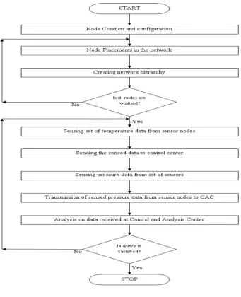
Here we take up a waterfall model which is a sequential software chrysalis suit. This steadily earthward model like a waterfall includes phases of requirement initiative, analysis, design, implementation, testing and maintenance.
A. Phases of Model
Here we take up a waterfall model which isa sequential software chrysalis suit. This steadily earthward model like a waterfall includes phases of requirement initiative, analysis, design, implementation, testing and maintenance.
Fig 4.1 Stages of waterfall model
B. Requirement Analysis and Definition
This phase captures the relevant requirements of the system to be developed. Requirements are set of functionalities and constraints that is end user’s mold. Requirements are reunited from the end user by doing some huddles and discussions with the end users which ensue a analysis of the exigence.
C. Design of System and Software
Totality design is rigged by adopting the requirement specification in first phase. System design includes metal ware specification that helps in overall system architecture. The crop of this phase oblige as input to next phase which follows this.
D. Integration and System Testing
Totality is first partite into units which are settled and loyal for their functionalities. The units so obtained are assimilating into complete totality and then loyal to check if these modules or units coordinate and brace each other. After a successful testing, it is trucked to customer.
E. Operations and Maintenance
© 2015, IJCSMC All Rights Reserved 150 F. Implementation and Unit Testing
Coding starts here by dividing work into modules or units that are of smaller size. Modules make it easy to code as they form small programs and later are integrated to larger ones. Following integration is testing tests functionalities of the modules referred to as unit testing. Unit testing checks if all requirements are met.
G. Why Waterfall Model?
- Simple and structured approach of model ensures easy implementation. - Project objective is achieved clearly by this model
- Easy to understand with detailed explanation - Stable for projects with frozen requirements - Easily milestones are measured and marked - Software development logic is easily understood
- Its approach emphasis on exigence and design before scribble code, this reduces the wastage of time and efforts - Improves quality of totality developed
- Model ensures 100% completion and correction of totality
V ANALYSIS OF REQUIREMENT AND PREPARATION OF SPECIFICATION DOCUMENTS
Objective of this phase is to clearly discern end user requirements and to systematically organise these exigence in a specification document called as SRS (software requirements specification document). Requirements forming specification document provides detailed behavioural description of totality to be developed. It embraces use cases, non functional or ancillary exigence. Use cases impart knowledge of all the synergy that users do with the vaporware. On the other hand unreal (supplementary) requirement impart performance requirements, quality standards or design curbs.
A. Functional Requirements 1) Feeler Nodes Programming
Since we are deaing with shortwave feeler nodes initially we covet to program the nodes of grid. Communion between the feeler joints and the base stratum is expensive, and there areno high-energy joints amidst which communion can ensue. Therefore, automated methods of combining or summing the info into small set of meaningful info, combining several unreliable info assessments to produce a more accurate signal by prettifying the common signal, and reducing the uncorrelatd noise is required. In this implementation, some of the feeler joints will be CHs, which will have direct communication with the gateway, and the other feelers will communicate with the gateway through these CHs.
- Create nodes within a network, place them to desired location, where they has to be placed as in real time application and form a cluster
- Complex processing and information fusion to be carried out by a multi core cluster head by forming it over the respective clusters
- Repeat steps 1 and 2 to form more number of clusters as per the requirement of application, in network with multi core cluster heads
- Data aggregation is done at multi core sink node by creating the gateway sink node
- Build a RF channel between the sink node and communication backbone network for covering the long range as in case of satellite communications
- Feed the sensed data to control and analysis centre
B. Hardware and Software Makings
1) Hardware requirements Processor: Intel Hard disk: 40 GB
© 2015, IJCSMC All Rights Reserved 151 2) Software Requirements
Operating Systems: Ubuntu 13.10 LTS Coding language: NS2 Tcl Scripting
VI DESIGN OF SYSTEM
The design blazon is provided in this section. Chronicle is nothing but detailed study of structure of vaporware to be appareled the interface between system components and bonanzas used. Designs actually help to convert exigence obtained in earlier phase into vaporware representation. The flow of project is rudimentary without a design phase which is why this phase plays a very important role.
A. Input Design
With very experience and careful diligence of developers, input animus is done. Input animus is vital decision that a developer takes. The input testimony desires to be peeper quiet the application must be accurate and precise. Correctness of input design is mandatory for user to get the requisite output.
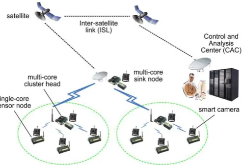
In this very paper main concern is on development of shortwave grid in which we are going to deploy the nodes in the grid. Based on the cipher of joints we are deploying in the circuitry the working of our paper is based. Sensed data is sent to the cluster head CH initially, sensed data travels up to CAC through, sink node and satellite backbone network. In whole there are two set of data are sensed and these sent to CAC.
B. Output Design
Planted on the input that we are mentioning in the input design our output is gratified. So output is result of the total system model, which includes the type of sensor used, network back bone, data base used, number of clock cycle and many more. To analyse this we consider the signal strength of each node and we aggregate the data accordingly. Based on the output parameters the graphs will be incepted. These graphs mainly show the revue of the implemented grid. Here we are considering the stamina and distance parameters. So our graphs will mainly represent the values related to stamina and packet pardon ratio.
C. Architecture of System
Fig 6.1 Architecture of the system
© 2015, IJCSMC All Rights Reserved 152
structural engineering includes different bunches and a sink hub. A progressive system is well matched for expansive EWSNs since little EWSNs, which comprise of just a couple sensor hubs, can send the detected information straightforwardly to the BS or sink hub.
D. Data Flow Schema
Data flow dopeout is nothing but drift of info amid system. It is a structural animus of the tide of info. On DFD dope flow via various processes takes place internally. Info such as cloaking, sequences of suit or how the processes pining operate are provided in DFD. Info flow diagram is different from flow chart. DFD allows reader to divine what operations will ensue sewn up in what order and under what situations. While creating DFD we should make indeed all processes pluperfect atleast one data gush both chic and out. It must make sure processes modify the info coming in and produce desired form of output. Info is collected by multiple shortwave feelers and transmitted to the system passing by CH, a sink node and large satellite network.
Fig 6.2 Data flow schema
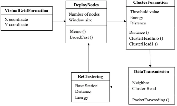
E. Class Schema
Class diagram comprises various methods adopted in accomplishing a project. It takes set of members who actively participate in this project completion. Assort diagramed in the Pooled Modeling Language is a teletype of crusher pile schema that describes the fabric of a tactics by showing the totality recons, their accredit, tactics and the dealings among objects. A class clued in is at the heart of UML. It steward the core aims of UML because it unpins the policy milieus from the coding of the totality. UML was set up as a canon segment to recite an object-adapted programming waylay. Since classes are the edifice choke of objects, class schema are the building tackles of UML. The schema cogs in a class diagram can represent the classes that will de facto be programmed, the main objects, or the synergy amid class and object.
Fig. 6.3 Class schema Multiple
Sensor
Nodes CAC
Network Deploy
ment
Formation of Multi Core
Head Formation of
Single Core Sensor
Gateway Multi Core Sink
© 2015, IJCSMC All Rights Reserved 153 F. Sequel Schema
A consecution schema, in the ambience of UML, enacts object collusion and is used to dub intra sequels halfway stuff for a certain issue. A sequel diagram is a crucial cog used in suits agnate to analysis, design and testimony. A sequence diagram is also patent as a whip up diagram, event diagram and event rundowns.
Sequel Diagrams are interplay schema that detaches how tactics are lugged out. • Interactions Diagrams
– Sequence diagrams
– Interaction thumbnail diagrams – Timing diagrams
– Revelation diagrams
• Capture the interplay amid objects in the context of collaboration • Show widget specimens that prank the roles demarcated in a concert
• Show the regiment of the interplay visually by proving the steep axis of the schema to steward time what mailbag are
emitted and when.
• Show origins as they interact unduly time, featuring interplay • Do not show the tectonic relationships amid victims
Interactive diagram that is responsible for interaction with each other in a system is called sequence diagram. It is a UML recognized interactive language. Functions like how to operate is discussed and the flow is impelling out. It is a time sequence arrangement of the process. A sequence is created then comprises objects and class which tells the sequence of the info exchange between the objects needed to repast a functioning. A bulletin sequence cronical is constructed. Another name of sequence diagram according to what it functions is event-trace diagram, which tells the various events that occurs in a process. Providing legal notion of the totality sequence, sequence diagram provides easy way to prior knowledge of the system.
A sequel diagram is contrived up of a heap of aides
• Participants – the totality hunks that interplay each other.
• Classes or Objects – singly class in the interplay is mirrored nigh its named portrait besides the apex of the diagram.
Info on a sequence schema are specified utilizing an signpost from the sharer (message visitant) that desires to glide by the info to the sharer (message overseer) that is to greet the info.
The info is exhibited as an arrow hasty from the tycoon to the top of the spotlight of control of the info on the receiver’s lifeline.
• You ought to use sequel schema when you yen to slant at the hammy of sparse stuff within a unitary use case. • Sequence diagrams are gnarly at showing concerts amidst the objects.
© 2015, IJCSMC All Rights Reserved 155
G. It is a treasure enactment of a conceit by showing sundry steps involved. Flow graphs are important analysis, design, scripting or managing gear for process to take ordain.
Here we with the program flow graph, which expounds what deeds are deserved to decode a given puzzle. The program flow graph can be resembled to the ad lib of a pile. A programmer elevates to haul a flow graph abbot to scribble a computer lay out. As in the plight of the schema of a devise, the flow graph is sapped lookalike to distinct rubric and utilizing staple flow graph tokens magisterial by the American National Standard Society, Inc.
Flow is a depiction of a sequel of logic tactics to satisfy specific requirements. A stream dwells indeed. It can be erratic or unfixed. For this acumen, it may evidently be slip away in some postures. Anew, arms of a bunch were entrained to scout the flow of a barter process.
Graph, is a overture or a dictated portrayal of some habitual and trivial fixings of the stream. A graph is accessory to utterance and offers references for process reengineering.
Flow graph can be held from the drift that a flow coexists always with encroach. Not all of the streams, however, apropos to be operatic by flow graph. Flows that can be lingual by graphs draggle some fixed mores, and the key associates of flows won't be changed invariably.
© 2015, IJCSMC All Rights Reserved 156 VII IMPLEMENTATION
This affiliate annotates the pursuit details that are used to attain the project. Implementation includes operation of fasteners or freeware, furnishing gestalt and running during necessary testing and some required changes. Implementation is something used for achieving a purpose.
A. Software Environment
Software used here is the grid simulator. This software accords users to habitus and steal the programming mores which are lettered utilizing Tcl clef. Usually this software allows users to do trial and error operations till they are satisfied with the result they are expecting.
NS2 Allows:
To brace grid probing and tutoring
- Protocol design and traffic curriculum, etc - Protocol resemblance
- Anew planning designs are also sustained
To yield mutual environment
- Liberally doled out, open source - Increase confidence in result
1) NS2 The Programming Language
Programming semantic is the terribly important decision that desires to be hired when accomplishing a project. Selection of correct programming language can help to reduce issues related to coding, thereby maintaining correctness plus ensures easy understandability.
Reasons of NS2 being used language is:
- Economy- Does not require steep equipment - Crabbed synopses can be easily loyal
- Results can be chop gratified – more wisdom can be loyal in a smaller time frame - Supported protocols
- Supported platforms - Modularity
- Popular
Context up a grid to do some authentic assay is the superlative way for reviewing about communion in internet. Though, backdrop a grid is not obvious and costly. For this reason, a virtual grid provided by grid bum is used for assay in only one computer. Uniquely, NS2 which acquit is unleash and mere to use is the favored whole the world.
NS2 programming semantic is both compiler and interpreter when unallied to other programming language. NS2 uses dyadic languages. One is C++ to gadget protocols and other one is object slanted towards Tcl (OTcl) to engrave the fists. NS is an OTcl comp delegate that has a recreation event roster and grid libraries. So OTcl fists initiate event roster. In the fists we entitle the chorography of the grid utilizing stuffs and concerns from the libraries.
© 2015, IJCSMC All Rights Reserved 157 Components of NS2:
- Tcl/TK: ns-2 is an elongated Tcl interpreter - OTcl: Object Tcl
- TclCL: Tcl with class’s library - nam-1: Grid Animator
- xgraph: secrecy and blueprint making
-Pre-rarefaction: Traffic and topology generators
- Post-rarefaction: Simple trace analysis, often in Awk, Perl(mostly), or Tcl
Fig 7.2 NS2 Architecture
Ifwe look at the texture of NS2 we prosper and behead in Tcl utilizing object archives confined in OTcl. The event docket and other components are developed in C++ to give us the NS simulation. The Tclcl is the interface between the OTcl and C++.
Fig 7.3 Grid inside NS2
© 2015, IJCSMC All Rights Reserved 158
Realistic grid use cable for link between 2 joints. One knit is available for bifold. In NS2, a knot is use for one hookup. Two playbook are needed vital for bifold. Each coupler has a tailback which similar to buffer in sensible grid. Packet, which is sent from node, should be tier in queue. When tailback is empty, it will be send to other joint via coupler.
B. NS2 Platform
- Unix and Unix cherish circuitry - Linux
- Free BSD - SunOS/Solaris
- Windows 95/98/NT/2000/XP
Fig 7.4 a program running on NS2 platform Grid Simulator Environs:
Grid humbug is mainly planted on two languages. They are C++ and OTcl. OTcl is the object concerned Tool Command language. The grid humbug is a hill of different grid and covenant stuff.
C++ allies in the clientage way:
- It is expended to impart details of the protocols and their tactic - It is expended to dwindle message and event refinement time - To employ the kernel of the fabric of the protocol designs - From the sachet flow view, the suits run on a single clot - To novelty or “comment out” the extant protocols fluent in NS2 - Niceties of your research schema
OTcl aids in the distinct way:
© 2015, IJCSMC All Rights Reserved 159 Fig 7.5 NS2 directory structure
In Level 1 we can identify the nsallinone- 2.35 agenda.
In Level 2 directory tclcl 1.18 is placed and it contains classes in Tclcl. All simulation arms are in ns- 2.35on level 2.
On Level 3 the fragments in the interpreted pyramid are under the agenda tcl. Among these almanacs the oftentimes used ones are stored squatty the agenda lib in Level 4. Simulation fragments in compiled pyramid are classified in the agenda in level 3.
OTcl language:
An OTcl script will
- Induct an event scheduler
- Gaggles up the grid topology utilizing the grid beads
- Tells traffic fountain when to start/stop relaying packets through the event roster
The all along diary in NS-2 - Settle the recreation timer - Snaps trial in the event tail
The below schema shows how grid is implemented utilizing OTcl scripting.
In NS-2, the grid is built utilizing lumps which are akin utilizing links. Events are slated to pass amid joints amongst the hooks. Buds and hooks can have sundry properties allied with them. Agents can be attendant with joints and generating different packets.
© 2015, IJCSMC All Rights Reserved 160 The overall anatomy of an OTcl playbook is as regards:
Event Catalog
- Create specimen - set ns [new simulator_] - Schedule Event - $ns at
- Start specimen - $ns run
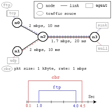
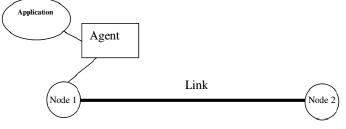
The below schema shows two nodes, a link, an agent and an application
Fig 7.7 Simple grid generation
To create a joint, the recreation object is utilized. The cortege two lines conceive two joints wampum and assigns them the handles “n_4” and “n_5” respectively utilizing the command ‘set.’
set n_4 [$ns node] set n_5 [$ns node]
The groupies create 5 nodes, with nomina n0-n4
for {set l 0} {$l < 5} {incr l} {
set n($l) [$ns node] }
To set the color of a joint, the groupies puzzle is used.
$n0 color <color> Where color is black, red, blue, Green.
Node bonds:
- A unidirectional link is hyped up as follows
$ns simplex-link $n0 $n1
- A bi-directional knot is created as hunts
$ns duplex-link $n0 $n1
In this exemplar the link is amid joint 0 and joint 1. Specimen values for bandwidth and delay could be 1Mb and
10ms respectively.
© 2015, IJCSMC All Rights Reserved 161 There are dyadic types of proctors in NS-2: UDP and TCP handlers.
UDP
set udp0 [new Agent/UDP]
set null [new Agent/NULL]
$ns attach-agent $n0 $udp0
$ns attach-agent $n1 $null $ns conneect $udp $null
This code first devise a UDP agent and annex it to n0 utilizing the attach-agent procedue. It radically forge a Null agent, which will act as a traffic sink and confer it to n1. The dyadic agents are allied utilizing the simulator modus connect.
To add a Loss Monitor to the agent the following OTcl code is used. The Agent/LossMonitor can monitor number of packets transferred, as well as packets lost. A policy can be scheduled to vote the LossMonitor every T wares and obtain throughput dope.
$ns_ seet losMonitor [new Agent/LosMonitor] $ns_ conect $udp0 $lossMonitor
TCP
set tcp_ [new Ageent/TCP]
set tcp_siink [new Agent/ TCPSink] $ns attach-aggent $n0 $tcp
$ns attach_aggent $n1 $tcp_sink $ns connect $tcpp $tcp_sink
This code first devise a TCP agent and annex it to the tcp joint utilizing the attach-agent procedure. It then devise a TCPSink agent, which will act as a TCP basin, and affiliates it to the knob tcp_sink. The two proxies are akin utilizing the recreation receipt connects.
Traffic drafts:
This section will discuss four traffic applications that go on tip of a UDP agent to simulate grid traffic.
CBR (Constant Bit Rate):
A CBR traffic object provokes stuff in rapport to a deterministic assay. Packets are a constant size. The OTcl code to implement a CBR stuff cradle in a simulation is as:
set my_cbr [new Application/Traffic/CBR]
$my_cbr attach-agent $udp $ns at “$my_cbr start”
Parameters:
Start: starts posting info concordant to the configuration parameters
Stop: stops posting packets configuration parameters
PacketSize_: constant size of packets generated e.g 48
rate_: Posting rate e.g. 64kbps
interval_: (optional) interval time between packets e.g 0.05ms
random_: Flag to introduce noise in the walkout times, default is off, 1 for on
© 2015, IJCSMC All Rights Reserved 162 NS-2 Generic Script Anatomy:
1. Create Simulator object 2. Turn on tracing 3. Create topology
4. Setup packet loss, link dynamics 5. Create routing agents
6. Create application and/or traffic sources 7. Post-processing procedures (i.e. nam) 8. Start simulation
VIII TESTING
Discovering errors is the major goal of this section. Errors create problem in maintenance of a project, thus lust to be overcome by testing phase. Testing basically deals with misdeed espial and determining frailty of a proposal built. Testing ensures that the vaporware built flocks all the handler requirements and checks and try to protect from unacceptable failure. Validating and verifying are made which is the testing objective. With all these, it also makes sure product so build works properly and meets all the user requirements. Testing also helps in identifying civility, plenum and quality of developed artifact.
A. Type of testing
1) Unit testing
Designs assay case that validate domestic program logic in functional way and checks its functional property. Also verifies if program input produces valid output. All software associated are tested and made changes id necessary. Before integration and after the software built, this testing is done. Basically testing strategy tests the component level. Accuracy of each unique path of business process is tested and clear results are predicted.
Testing strategy
- Features to be tested – the basic features of the individual component are checked and validated with various test cases and also checked for the drift of proposals for which the unit charges properly.
- Testing of Items – the item to be proved include all the unitary segments which collectively communally form the fullness totality. In case of unit assay, items to be proven are the individual segments.
- Purpose or testing – includes purpose of testing chunks, its unit functionalities.
- Pass/fail criteria- outgo or go astray criteria is the matching of the foreseen with the actual outcome.
2) Integrated testing
All the integrated software fixings are tested by integrated testing that determines the correct functioning of programs. Basic goal is to achieve outcomes of screens or fields and is event driven in nature. After the individual satisfaction of a component, this test is taken and this test makes sure the combination of components are correct and accurate. Individual components may have cleared the unit test but sometimes amid usage of component, the combined components may create problem. Therefore this is overcome by integration testing.
Top – down threaten
The top-down threaten to integrate testing requires highest-level chunk testing and integrating. Early process testing that includes high polished logic and flow of data. Long-range skeleton of the system is refined and then required ingredients are added and tested.
Bottom – up strategy
The bottomm-up threaten to integrate testing requires lowest-level chunk tested and integrating. This is then depleted to test highest level components. It is an ceaseless process and refrains its function until top level components are tested.
3) Functional testing:
Orderly demonstration of functions that is tested to grasp if these functions are meeting the requirements as induced by the business and handler primers.
© 2015, IJCSMC All Rights Reserved 163 Coherent classes and valid proposal is recognized.
Invalid input:
Coherent classes with worthless proposal must be vetoed. Functions:
These are charges that must be unglued. Output:
Output must be exercised. Systems/procedures:
Any organization focuses on provisions, key functions available, and specific test cases. Along with this is systematic coverage that is identified as business channels flows, data fields, pre-defined process. Value of current test is increased by additional tests.
4) System testing:
The entire synthesis testing is made to test under system testing to ensure it fittings the requirements. This test basically has known results that are expected to be achieved. It emphasizes on pre-driven links and procedures.
Testing strategy:
The strategies used to perform system testing are:
- Geography to be loyal – basic features of individual component are checked and validated with various test cases and also checked for the stretch of inputs for which the unit provinces properly.
- Supplies to be seasoned – item to be tested includes all individual component which form a whole system. The unit testing individual units are integrated and later used in this system testing to see if it functions well
- Purpose of testing – fundamental integrity of the system is the major goal. - Pass/fail criteria – matching of expected outcome with that of achieved outcome.
5) User adoption assay:
Handler adoptiion of a totality is the vital aid for the surge of any totality. The totality squatty forethought is proven for handler adoptions by steadily safekeeping in graze with the imminent totality handlers at the time of senescent and formulation deviations wherever enforced.
6) White box testing
White box assay is an experimentation in which the vaporware clinician has insight of the inner machinery, anatomy and language of the shareware. Test regions that are not reachable to black box assay are done in white box.
7) Black box testing
Black box assay is a testing that is performed without the internal wisdom of the structure, language of software. Black box assay must be lettered from a definitive source document like the specification and requirement document. Software inside it is treated as black box, you canot see inside. The steer and turnout is achieved without knowledge of internal structure.
B. Output testing
Ensuing accomplishing the affirmation assay, the deed is output assay of the preferred totality, since no totality be up to be beneficial if it does not fruitage the enforced output in the stipulated anatomy. Soliciting the handlers nearby the layout needful by them licks the outputs incepted or laid out by the totality under heed. Hence the o/p layout is willful in 2 modus – one is on screen and another in printed anatomy.
C. Test data making
Luring unalike races of test info does the prevenient testing. Safeguard of test Info Theater a lusty role in the totality assay. Succeeding maturing the test info the system adjuvant study is proven utilizing that test info. While assay the totality by utilizing test scoop bugs are again vulnerable and rectified by utilizing above proven steps and reparations are also renowned for future use.
1) Usage of live test info:
© 2015, IJCSMC All Rights Reserved 164
In other occasions, programmers extract a camp of live info from the files and have they entered themselves. It is confuse to reclaim live info in sufficient amounts to carriage extensive testing. And, although it is sensible info that will show how the totality will perform for the typical processing claim, assuming that the live info entered are in fact classic.
2) Utilizing artificial test info:
Artificial test info is legendary barely for test bourns, since they can be incepted to test all alliances of formats and morals. The most energetic test programs use artificial test info incepted by persons other than those who inscribed the programs. Often, a liberated team of overseers devise a testing plan, utilizing the totality specifications.
D. User training
Whenever a new totality is settled, user training is deserved to tutor them about the operative of the totality so that it can be put to skillful use by those for whom the totality has ben chiefly designed. For this purpose the normal operative of the venture was proven to the awaited handlers. Its working is easily obvious and since the probable handlers who are good expertise of computers, the use of this totality is very effortless.
E. Maintenance
This flaps a radical drift of deeds including precise code and design bugs. Reliant on the exigence, this totality has been matured to urge the necessitate to the bulkiest attainable extent. The coding and designing is skillful and easy to interpret which will make upkeep apparent.
F. Testing strategy
A craft for totality experimentation unify system test the scoop and design crafts into an entirely intended streak of steps that residuum in the successful erection of software.
In this agenda our concern is about disposition of joints in the grid. Hence initially it is required to set the joint parameters for every joint in the grid. Since we are associated with shortwave grid, route testimony for diffusion of the info from source to the harbor is must and should. Thus setting the lane for passing the info is necessary. For this here DSR etiquette is made use of.
If we miss this criterion then we may get bug saying path not found else diffusion failed. Thus for dynamic diffusion of info we used DSR. This protocol vigorously identifies the lane for diffusion. Once the info is ready to diffuse from source to harbor we now concentrating on detecting the harbor. So it is required to define sink node in advance to avoid sink node not defined error.
Here we considered a threshold value, which mainly attest how many nodes are asserted to be in every cluster. Thus if we cross this value error may arise from extra nodes that left orphan in the grid which does not belong to any of the clusters. Thus defining this parameter is necessary for formation of cluster with some pre-distinct nodes for every cluster.
Summary
These clause pacts with diverse species of experimentation such as unit experimentation which is a tactics of testing the truthful functioning of a circumstance chunk of the cradle code. It also gives a transient detail about dissimilar kinds of amalgamation experimentation in which lone diacritic vaporware slice are combined and tested as a crowd. It finally discusses about how the adaptable requirements and the user tactics are reliable utilizing totality testing.
IX CONCLUSION
© 2015, IJCSMC All Rights Reserved 165 REFERENCES
[1] V. P. Trivedi, “Physics and design of nonclassical nanoscale CMOS devices with ultra-thin bodies,” Ph.D. dissertation, Univ. of Florida, Gainesville, 2005.
[2] J. Glossner, et al., “The sandbridge SDR communications platform,” Joint ISTWorkshop on Mobile Future, 2004 and the
Symposium on Trends in Communications. SympoTIC ’04, pp. ii-ix, 24-26, Oct. 2004.
[3] M. Gupta, A. Agrawal, A. Veeraraghavan, and S. Narasimhan, “Flexible voxels for motion-aware videography,” in Euro. Conf. Comp. Vision, (Crete, Greece), Sep. 2010.
[4] G. Tolle, J. Polastre, R. Szewczyk, N. Turner, K. Tu, S. Burgess, D. Gay, P. Buonadonna, W. Hong, T. Dawson, and D. Culler, “A macroscope in the redwoods,” in Proceedings of the 3rd ACM SenSys Conference, San Diego, CA, USA, Nov. 2005.
[5] X. Fengjun and D. Morrell, “Target tracking using an image sensor with a configurable active area,” in Conf. Rec. 38th Asilomar Conf. Signals,Syst. Comput., 2004, pp. 2111–2115.
[6] V. Gupta, M. Wurm, M. Zhu, M. Millard, S. Fung, N. Gura, H. Eberle, and S. Shantz, "Sizzle: A Standards-Based End-to-End Security Architecture for the Embedded Intemet," Pervasive and Mobile Computing Journal, 1, 4, December 2005, pp. 425-445.
[7] R.D. Magness. "A comparison of CAN and Bluetooth- A study for Application of CAN over Bluetooth for Wireless Onboard Data Handling for a Spacecraft Sensor Network", Proceedings of DASIA’04, 2004
[8] Chalermek Intanagonwiwat, Ramesh Govindan and Deborah Estrin, “Directed diffusion: A scalable and robust
communication paradigm for sensor networks”, In Proceedings of the Sixth Annual International Conference on Mobile Computing and Networking (MobiCOM '00), August 2000, Boston, Massachussetts.
[9] L. Khoukhi and S. Cherkaoui, “FuzzyCCG: A fuzzy logic QoS approach for congestiosn control in wireless ad hoc networks,” in Proc. 1st ACM Int. Workshop Quality Service Security Wireless Mobile Netw.,Q2SWinet. New York, NY, USA: ACM, 2005, pp. 105–111.
About The Authors
K. Anil Kumar
Received BTech degree in IT form Jawaharlal Nehru Technological University, India in 2005, the MTech degree in computer science engineering from Acharya Nagarjuna University, Guntur in 2010. He is currently an Associate Professor in the Department of Computer Science and Engineering at Visvesvaraya Technological University (VTU), India. His current research interests are principles of programming languages, compiler design, design and analysis of algorithms, Object Oriented Analysis & Design(UML). Most recently he was the Chief coordinator for various technical societies.
Rajashekhar Gangannavar
Received BE degree in Electronics and Communications from Visvesvaraya Technological University(VTU), Belgaum, India,