Design and Experimental Verification of Adaptive Speed Region
Control for Hybrid Excitation Claw-Pole Synchronous Machine
Yang Zhang1, Quanzhen Huang1, *, Mingming Huang1, Duane Decker2, and Yuhao Qing1
Abstract—With combining the advantages of the hybrid excited synchronous machine and claw pole machine, hybrid excitation claw-pole synchronous machine (HECPSM) exhibits merits of controllable flux operation and independent flux paths. One novel wide range adaptive speed region control strategy is proposed in this paper, based on the analysis of the field control capability of HECPSM and the space vector control. Independent control methods of maximum torque per ampere (MTPA), space vector and minimum copper loss (MCL) control were employed for the proposed machine during three different speed regions in order to obtain satisfied performance in the whole speed range. The correctness and effectiveness of the proposed adaptive speed region control strategy and drive system design were verified by simulation and experimental results, which demonstrated that the proposed control strategy maximized the range of speed regulation while exhibiting the high efficiency.
1. INTRODUCTION
As one novel emerging branch of permanent magnet synchronous machine (PMSM), hybrid excitation synchronous machine (HESM) has drawn extensive attention in past decades since it incorporates the merits of PMSM with the possibility of controllable flux by auxiliary excitation windings [1]. Compared with those traditional PMSM and reluctance machine for the application of industrial fields [2, 3], HESM is a promising candidate due to the feature of wide range speed regulation operation by adjusting the excitation current and d-axis current, especially for electric vehicles (EVs), hybrid EVs and servo systems [4–6]. In recent years, several different potential solutions of HESMs exhibiting the claw pole topology [7–9], namely, hybrid excitation claw-pole synchronous machine (HECPSM), have become a key research subject since they have the advantages of HESM and simple claw-pole structure.
Several PMSM and HESM control methods have been developed to realize wide range operation for HECPSM due to the similarities of machine structure and performance in [10–13]. A hybrid excitation brushless DC motor fuzzy control scheme was presented in [14], which regulated armature and excitation current by using a fuzzy controller. A common coordinate system for HESM based dynamic vector control model was proposed in [15], and then a copper loss minimization vector control method for non-salient pole HESM was tested in [16] based on id = 0 control. A fuzzy control with particle
swarm optimization algorithm was proposed and simulated to improve the efficiency and stability of the HECPSM in [17]. A simplified control method for HESM was proposed in [18], and its coil current and direction were controlled by stator winding current and the back EMF. In addition, a maximum torque/copper loss control method for HECPSM was presented in [19], and a simplified subsection control strategy and no excitation current control mode were carried out and compared in [20], respectively. All these research works have positive reference to reveal the electromagnetic property of HECPSM. However, as one embranchment of HESM, HECPSM has already been proved
Received 26 September 2018, Accepted 12 November 2018, Scheduled 28 November 2018
* Corresponding author: Quanzhen Huang (hngcxy [email protected]).
1 School of Electrical Information Engineering, Henan University of Engineering, Zhengzhou 451191, China. 2 School of FOCUS
a multi-variable nonlinear high order system with strong coupling [21], and its the electromagnetic torque was related to d-axis current, q-axis current and excitation current together. The influence of power supply voltage was not considered in the process of flux-weakening control, which means that the flux-weakening of d-axis current was not utilized. Once the excitation current could not provide adequate flux-weakening effect, it seemed extremely difficult for the machine to fulfill the speed regulation without considering d-axis current. For those control methods above mentioned, optimal comprehensive performance could not be maintained through the flux-weakening control operation due to the static flux-weakening coefficient. Once the machine works in different operation states, it could not be taken into account both the efficiency and the speed range at the same time. Hence, a reasonable allocation strategy of excitation and armature current should be integrated consideration to achieve optimal static and dynamic characteristics with the existence of an additional controllable excitation current.
This paper is organized as follows. The topology and its mathematical model of the proposed HECPSM are presented in Section 2. Then, the proposed adaptive region control strategy for HECPSM is described and deduced in Section 3, which includes three parts, namely, maximum torque per ampere (MTPA) control, space vector control and flux weakening control methods in low-, middle- and high speed regions, respectively. The adaptive speed region control system simulation model for the HECPSM is established, simulated and analyzed in Section 4. Several experimental verifications under different operating states for the HECPSM are developed in Section 5, respectively.
2. TOPOLOGY AND MATHEMATIC MODEL OF HECPSM
2.1. Machine Topology
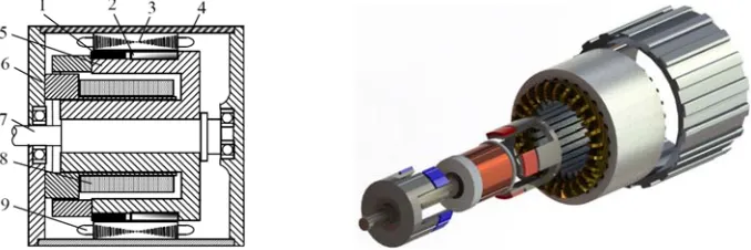
Figure 1 shows the structure of the proposed HECPSM, which is composed of dual stators and a claw-pole rotor. The armature winding and excitation winding are emplaced in outer stator and inner stator, respectively. The surface of claw pole on rotor is divided into two sections: one is a PM pole, and the other is a solid iron pole, which are interlocked with each other, as shown in Fig. 1(b). PMs create a nearly constant flux, while the field winding currents generate a variable flux; both form the resultant flux in the air gap. The magnetic field generated by the excitation current enters into the air gap mostly through the core because the magnetic resistance of PM is much larger than that of the core. Hence, when the motor works in flux-weakening or flux-enhancing, there is no risk of permanent demagnetization for the rotor PM.
It can also be seen from Fig. 1(b) that the magnetic field of the HECPSM produced by the excitation current has a slight degree of coupling on the magnetic field produced by the armature current and PMs, which means that the air-gap magnetic field of HECPSM can be regarded as approximated linear superimposition. The air-gap magnetic field can be adjusted effectively by changing the size and direction of excitation current and the d-axis current.
1. permanent magnet 2. iron pole 3. stator core 4.enclosure 5. claw pole 6. end closure 7. shaft 8. exciting winding 9. armature winding.
(b) (a)
2.2. HECPSM Mathematic Model
Hence, neglecting the influence of the temperature, magnetic saturation, and hysteresis loss [22], several basic equations of the HECPSM, including voltage, flux linkage and electromagnetic torque, can be expressed as Voltage equation: ud uq uf = ⎡
⎣ Rsω+eLsLd d R−sω+eLsLqq ωsMeMsfsf
sMsf 0 Rf+sLf
⎤ ⎦ id iq if + ⎡
⎣ ωeψ0pm
0 ⎤
⎦ (1)
where ud, uq are the d- and q-axis armature voltage components, respectively; uf is the excitation
voltage,Ld,Lqare thed- andq-axis inductance, respectively;RsandRf are the armature resistance and
excitation winding resistance, respectively; Msf is the mutual inductance between armature windings
and excitation windings; ωe is the electrical angular velocity; id, iq are the d- and q-axis current
components, respectively;if is the excitation current; ψpm is the permanent magnet flux linkage.
Flux linkage equation:
ψd ψq =
Ld 0 Msf
0 Lq 0
id iq if + ψpm 0 (2)
whereψd,ψq are the d- and q-axis flux linkages.
Electromagnetic torque equation:
Te=
3
2piq[ψpm+id(Ld−Lq) +Msfif] (3)
3. ADAPTIVE CONTROL STRATEGIES IN THREE DIFFERENT SPEED REGIONS
For an HECPSM control system, two typical operations should be fully considered [23], including a large starting torque by the flux-enhancing control below the rated speed and a wide adjustable speed range for high-speed cruise by flux-weakening control above the rated speed. Hence, according to different operations, the proposed control strategy for the whole speed range can be divided into three speed regions: low speed, middle speed and high speed.
3.1. Maximum Torque Per Ampere (MTPA) Control in Low Speed Region (nr≤nN)
Available maximum output torque in low speed region is important to the drive system of HECPSM, which means that a quick response can be realized timely [24]. When the operation speed of the proposed HECPSM is less than or equal to the base speed nb, excitation current for speed adjusting is adopted
according to its load torque. With the purpose of improving the operation reliability of HECPSM, a maximum torque current ratio control method based onid= 0 is adopted, and the torque equation can
be obtained by
Teref =
3
2p[ψpm+Msfifref]iqref (4) where,Teref is the reference value of electromagnetic torque;ifref andiqref are the referenceq-axis current
component and excitation current component, respectively. WhenTeref is small, it satisfies
Teref ≤TN =
3
2pψpmIqN (5)
whereTN is load torque, IqN is the base value of q-axis current.
In this case, no excitation current is needed for speed regulating, andTeref can be changed by only
adjusting the value of iqref, thus, the reference current ofiqref can be expressed as
iqref =
2Teref
3pψpm
WhenTeref is larger thanTN,
Teref > TN =
3
2pψpmIqN (7)
The flux-enhancing control is adopted, and the reference currentifref is given by
ifref=
2Teref −3pψpmIqN
3pMsfIqN
(8) Hence,Teref can be further rewritten as
Teref =
3
2pψpmIqN + 3
2pMsfifrefIqN (9)
In summary, when Teref ≤TN, the reference currents can be expressed as
⎧ ⎪ ⎪ ⎨ ⎪ ⎪ ⎩
ifref = 0
idref = 0
iqref=
2T eref
3pψpm
(10)
WhenTeref > TN, the reference currents are given by
⎧ ⎪ ⎪ ⎨ ⎪ ⎪ ⎩
ifref =
2Teref−3pψpmIqN
3pMsfIqN idref= 0
iqref =IqN
(11)
3.2. Traditional Vector Control in Middle Speed Region (nN ≤nr≤nBdec)
Once the machine speed nr exceeds the base speed nN, the HECPSM enters middle speed operation
region, and its back-EMF approaches the DC-bus voltage Udc. If the speed is to be further increased,
the flux weakening control must be carried out. The regulations of the armature current and excitation current are restricted by the voltage limit ring, similar to PMSM flux weakening control method in constant power region. For HECPSM, the flux weakening base speednBdecis one key parameter. When id =if = 0, vector control strategy is adopted, and it is equivalent to the traditional PMSM control,
which means thatnr is linear with the electrodynamic force of Eq.
When the operation is stable, the voltage vector magnitude meets
u2s =u2d+u2q ≤Ulim2 (12)
whereUlimis the maximum phase voltage magnitude, and its value depends onUdc.
It can be seen from Eq. (12), the value of us depends on uq, while uq is determined by theq-axis
component of the back-EMF Eq. Hence, a flux weakening control method based on maintaining the
back-EMF invariable is presented according to the above analysis, namely
Eq =Ebase (13)
whereEbase is the back-EMF under no-load operation whennr reaches nb. Ebase is expressed as
Ebase=pnBdecψpmπ/30 (14)
Hence,Eq can be rewritten as
Eq = pπn30r(ψpm+idLd+ifMsf) (15)
Whenid=if = 0, it is acknowledged thatnr appears linearly proportional toEq.
Therefore, the maximum speednmaxunder no-load and no-excitation current also appears to have
linear relationship with Udc when traditional vector control method is used. On the other hand, it
should be noted that flux weakening base speednb is restricted by nmax, and nmaxcan be obtained by
obtained by least square curve fitting according to the experimental data combinations of bus voltage and no-load speed, which can be expressed as
nmax=kvUdc+N0
nb =kbnmax
(16) where for the experimental prototype, the maximum speed to voltage ratio coefficient takes kv = 5.69,
offset value N0=−13.
To ensure the utilization rate of DC bus voltage and the motor efficiency in flux weakening operating state, the flux weakening base speed coefficient kb is set at range of 0.8 ∼ 0.95, here, kb = 0.85. So,
when the DC bus voltage value sets Udc = 300 V,nb = 1270 rpm. The current distribution strategy in
this region is relatively simple. When keepingidref = 0 andifref = 0, traditional PMSM control strategy
is suitable for HECPSM. Therefore, the reference value of each current can be expressed by ⎧
⎨ ⎩
ifref = 0, idref = 0
iqref =iTref ≤ IqN ·nN
nr
(17)
3.3. Minimum Copper Loss (MCL) Control in High Speed Region (nBdec≤nr)
Flux weakening base speednBdecis the demarcation point between middle and high speed regions. When
the machine speednr is larger thannBdec, the machine breaks the boarder of middle speed region and
comes into the high speed region. The amplitude values of air gap magnetic field and back-EMF are inversely proportional to the machine flux-weakening current. The larger the flux-weakening current is, the smaller the values of air gap magnetic field and back-EMF are, and the larger the q-axis current is required under the same load. Therefore, in order to minimize the copper loss of the machine, the excitation current should be adjusted appropriately to make the back EMF as close as possible to the terminal voltage. However, in fact, theq-axis current is determined by the load, and its current reference value is given by the speed controller, which means that it varies with the load and speed. Hence, the reference value of torque current cannot be taken into account when designing flux-weakening speed regulation of machine, and the value can be adjusted adaptively by the speed controller.
Thus, combining the expressions from Eq. (13) to Eq. (15), the following can be obtained (Ldidref+Msfifref) = ψpm
(nb−nr) nr
(18) It can be seen from Eq. (18) that voltage limit equation is different from that of traditional PMSM, and its control accuracy depends on the ratio ofnb/nr.
The copper loss equation in high speed region can be obtained by using copper loss minimization principle, and it can be expressed as
Pcu-ref =
3 2i
2
drefRs+i2frefRf (19)
wherePcu-ref is the reference value of machine copper loss.
In order to simplify the computation, the value of iqref is directly determined by the reference
electromagnetic torque Teref. Thus, it does not include the copper loss produced byq-axis component
currentiqref in Eq. (19), and iqref is given by
iqref =kiTeref (20)
whereki is the q-axis current to torque ratio coefficient.
Combining Eq. (19) and Eq. (20), the Lagrange multiplier is adopted to get reference current values based on copper loss minimization control method, and they are defined as
L(idref, ifref, λ) =Pcu ref+λ
(Ldidref+Msfifref)−ψpm
(nb−nr) nr
To solve partial derivative ofidref,ifref and λfor Eq. (21), respectively ⎧ ⎪ ⎪ ⎪ ⎪ ⎪ ⎪ ⎨ ⎪ ⎪ ⎪ ⎪ ⎪ ⎪ ⎩ ∂L ∂idref
= 3idrefRs+λLD ∂L
∂ifref
= 2ifrefRf +λMsf ∂L
∂λ = (Ldidref+Msfifref)−
ψpm(nb−nr) nr
(22)
Assuming ∂i∂L
dref = 0, ∂L ∂ifref = 0,
∂L
∂λ = 0, the values of idref and ifref are as follows
⎧ ⎪ ⎪ ⎨ ⎪ ⎪ ⎩
idref=− Ld
3Rsλ ifref =−Msf
2Rfλ
(23)
whereλ= 6RsRfψpm(nr−nb) nr(2RfL2
d+3RsMsf2 )
.
In summary, speed region current allocation method can be used to obtain flux weakening control for the HECPSM. Firstly, the realization of flux-weakening control is based on copper loss minimization idea, which regulates iqref, idref and ifref together. The corresponding reference values for each current
component are given as
⎧ ⎪ ⎪ ⎪ ⎪ ⎨ ⎪ ⎪ ⎪ ⎪ ⎩
iqref =kiTeref
idref=− Ld
3Rsλ ifref =−Msf
2Rfλ
(24)
Secondly, the flux weakening control is implemented by only using the excitation current, namely
idref=0, and the corresponding reference values for each current component are given as
⎧ ⎪ ⎪ ⎪ ⎨ ⎪ ⎪ ⎪ ⎩
iqref =kiTeref
idref= 0
ifref = ψpm
Msf
nb nr −
1
(25)
4. MODELING AND SIMULATIONS
To investigate the effectiveness of the proposed adaptive speed region control strategy, HECPSM simulation model was established by using MATLAB/SIMULINK. Fig. 2 shows the control system model of HECPSM, which includes HECPSM module, reference current calculator, transforms of inverse Clarke, Park and Ipark, Speed PID, Current Distributor,IdPID,IqPID, SVPWM,If PWM, Armature
Driver, andIf Driver. Compared with the traditional PMSM control system, HECPSM control system
has additional three functional modules of If PWM, If Driver and Current Distributor.
Current distributor divides the entire operation region of HESPSM into three regions: low, middle and high speed regions, according to the machine speed, respectively, as shown in Fig. 3. Different control methods are adopted to the three regions to investigate the machine performance. The key function of current distributor coordinates the allocation of the armature current and excitation current to realize a reasonable distribution of the current reference values for the machine operations among three speed ranges, hence to ensure the stable, reliable, efficient operation for the HECPSM.
The major parameters of the studied HECPSM are tabulated in Table 1.
Figure 2. Control system model of HECPSM.
Figure 3. HECPSM current distribution module.
Table 1. Main specifications of the proposed HECPSM.
Item (symbol) Value Unit Item (symbol) Value Unit
Rated power: PN 700 W Udc 300 V
Rated torque: TN 13 N·m Rs 2.7 Ω
Rated speed: nN 200 rpm Rf 33.0 Ω
Rated current: IN 5 A Lq 27 mH
Pole-pair number: p 4 - Msf 76 mH
Notes: If N+andIf N−rated flux-enhancing and flux-weakening excitation current, respectively.
1650 rpm, 2350 rpm and 4610 rpm with the three control strategies above mentioned, respectively. It should be pointed out that the operation speed is significantly extended with the combination control strategy ofd-axis current and excitation current. Fig. 4(b) shows the back-EMF waveforms of studied HECPSM under three different control strategies. The back-EMF values with no-field weakening current regulation and the combination ofd-axis current and excitation current grow fastest and slowest among the three ones. All of the back-EMF values are finally stabilized at 165 V. The electromagnetic torque value under the control strategy ofidandif co-action is larger than that of other two methods, especially
when the machine enters stable operation region, which is shown in Fig. 4(c). Similarly, when HECPSM works in stable region, the current value ofiqunder the control strategy ofidandif co-action is obviously
(b) (a)
(d) (c)
Figure 4. Simulation waveforms of the proposed HECPSM.
5. EXPERIMENTAL VERIFICATIONS
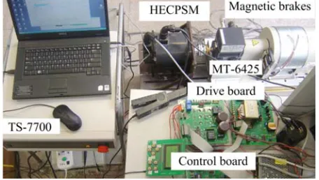
In order to verify the correctness of simulations results with the proposed speed region control strategy, HECPSM testing platform was established, and its controller was based on TMS320F2812 + AT89C55WD, as shown in Fig. 5. It contains five parts, HECPSM prototype, torque testing, magnetic brake, driver board and control board. TS-7700 Torque Station with MT-6425 torque detectors was used to test the motor torque characteristics. Rated DC bus voltage for HECPSM prototype was 300 V.
Figure 5. Experiment system of HECPSM.
Several experiments were implemented with different speed region control strategies. Fig. 6 shows the HECPSM starting current waveform with 1 Nm load. The given speed of HECPSM is 2800 rpm, which is faster than that of flux weakening base speed of 1270 rpm. With the purpose of improving the starting torque of the motor, a positive rated excitation current was applied half second ahead to the motor to enhance the magnetic field before starting the armature current due to the large inductance of the excitation winding. With the increase of the excitation current, the motor speed decreases gradually. When the speed reaches the basic speed nb, the flux weakening control for speed adjusting begins, and if and id continually increase toward negative part with the speed increasing.
500mA/div' vertical' 500mS/div' horizontal 2A/div' vertical'
500mS/div' horizontal f
i A
i
Figure 6. Test waveforms of starting current.
Figure 7. Steady-state current waveforms in flux weakening operations.
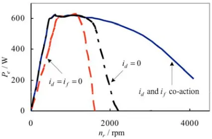
Figure 8. Maximum output power at different speeds.
which means that the harmonic is smaller.
Figure 8 shows the experimental results of the measured power-speed curves for three different control strategies ofid=if = 0,if control (id= 0), idand if co-action control. For the constant power
When the speed exceeds 1300 rpm, the output power decreases sharply, and there is almost no output torque and power when the speed reaches 1600 rpm. By adoptingid= 0 control strategy, the machine
constant power region was extended to 1600 rpm, and its maximum operation speed reaches 2200 rpm. Compared with theid=if = 0 as well asif control, the loading capacity increases in the flux-enhancing
condition, and the range of speed regulation is broadened in the flux-weakening condition when id and if co-action control strategy is used. With the excitation current regulation effect, the constant power
region was extended to 450∼1800 rpm. Although the constant power cannot be maintained, the output power decreased slowly. When the speed is up to 4000 rpm, it still stays at 200 W output power. The experimental results show that the load capacity of the studied HECPSM in the low speed and high speed operating region is effectively improved through the adjustment of the excitation current.
6. CONCLUSION
In this paper, a new type of HECPSM and its adaptive speed region control system were designed and established. According to the magnetic field adjusting property of HECPSM, one novel adaptive speed region control strategy for HECPSM was presented, which divided the whole operation region into three different speed regions. The operating performance of the HECPSM was investigated in the entire operating region. During the process of flux-weakening regulation in high speed region, the decoupling control was effectively realized by maintaining the constant back-EMF and adjusting thed-axis current and excitation current. As a result, the control algorithm of HECPSM was simplified. The experimental results demonstrate that the electromagnetic torque stays at 29.8 Nm in low-speed region by adjusting the excitation, and the maximum speed increases about 148% in high speed range with the proposed control method. Both simulated and experimental results show that the range of speed regulation is broadened as well as high efficiency, which verifies the validity of the proposed control strategy.
ACKNOWLEDGMENT
This work was supported by Scientific and Technological Program of Henan Science and Technology Agency (16A470004), the Technological Innovation Talents Projects of Henan Universities (17HASTIT020), the Fundamental Scientific and Technological Research Funds of Henan Science and Technology Agency (182102210252), and the Henan Province Youth Backbone Teacher Project (2016GGJS153).
REFERENCES
1. Spooner, E., S. W. Khatab, and N. G. Nicolaou, “Hybrid excitation of AC and DC machine,”
Proceedings of the International Conference on Electrical Machines and Drives, 1989 IEE Electrical Machines and Drives Conference, 48–52, 1989.
2. Chan, C. C., K. T. Chau, and J. Z. Jiang, “Novel permanent magnet motor drives for electric vehicles,” IEEE Trans. Ind. Electr., Vol. 43, No. 2, 331–339, Apr. 1996.
3. Peniak, A., J. Makarovic, P. Rafajdus, V. Vavrus, P. Makys, K. Buhr, and R. Fajtl, “Design and optimization of switched reluctance motor for electrical vehicles,” Electr. Eng., Vol. 99, No. 4, 1393–1401, Jul. 2017
4. Fuchs, E. F. and M. H. Myat, “Speed and torque range increases of electric drives through compensation of flux weakening,” 2010 Power Electronics, Electrical Drives, Automation and Motion Conference, 1569–1574, 2010.
5. Amara, Y., L. Vido, M. Gabsi, E. Hoang, and B. Hamid, “Hybrid excitation synchronous machines: energy-efficient solution for vehicles propulsion,”IEEE Trans. Veh. Technol., Vol. 58, No. 5, 2137– 2149, Nov. 2009.
7. Lawler, J. S., J. Bailey, and J. McKeever, “Minimum current magnitude control of surface PM synchronous machines during constant power operation,”IEEE Power Electr. Lett., Vol. 3, No. 2, 53–56, Jul. 2005.
8. Liu, C. C., J. G. Zhu, Y. H. Wang, Y. G. Guo, and G. Lei, “Comparison of claw-pole machines with different rotor structures,”IEEE Trans. Magn., Vol. 51, No. 11, 8110904, Jun. 2015.
9. Deodhar, R. P., A. Pride, and J. J. Bremner, “Design method and experimental verification of a novel technique for torque ripple reduction in stator claw-pole PM machines,” IEEE Trans. Ind. Appl., Vol. 51, No. 5, 3743–3750, May 2015.
10. Balagurov, B. A., “Electric generators with permanent magnets,” Elektroatomizdat, 1988.
11. Chen, J. J. and K. P. Chin, “Minimum copper loss flux weakening control of surface mounted permanent magnet synchronous motors,” IEEE Trans. Ind. Electr., Vol. 18, No. 4, 929–936, Jul. 2003.
12. Chan, C. C., R. Zhang, and K. T. Chau, “Optimal efficiency control of PM hybrid motor drives for electrical vehicles,” 1997 Power Electronics Specialists Conference, 363–368, 1997.
13. Gabriele, B., F. G. Capponi, G. D. Donato, and F. Caricchi, “Closed-loop flux-weakening control of hybrid-excitation synchronous machine drives,”IEEE Trans. Ind. Appl., Vol. 53, No. 2, 1116–1126, Dec. 2017.
14. Chen, J. J., “Automatic flux-weakening control of permanent magnet synchronous motors using a reduced-order controller,” IEEE Trans. Ind. Electr., Vol. 15, No. 5, 881–890, Sep. 2000
15. Shinnaka, S., “New dynamic mathematical model and new dynamic vector simulators of hybrid-field synchronous motors,” 2005 Electric Machines and Drives Conference, 882–889, 2005.
16. Shinnaka, S., “New optimal current control methods for energy-efficient and wide speed-range operation of hybrid-field synchronous motor,”IEEE Trans. Ind. Electr., Vol. 54, No. 5, 2443–2450, Jul. 2007.
17. Huang, M. M., H. Y. Lin, Y. K. Huang, P. Jin, and Y. J. Guo, “Fuzzy control flux weakening of hybrid excitation synchronous motor based on particle swarm optimization algorithm,” IEEE Trans. Magn., Vol. 48, No. 11, 2989–2992, Oct. 2012.
18. Zhang, Q. F. and S. M. Cui, “Hybrid switched reluctance motor applied in electric vehicle,” 2007 IEEE Vehicle Power and Propulsion, 359–363, 2007.
19. Wang, Y. and Z. Deng, “Hybrid excitation topologies and control strategies of stator permanent magnet machines for DC power system,” IEEE Trans. Ind. Electr., Vol. 59, No. 12, 4601–1615, Jan. 2012.
20. Yang, C. F., H. Y. Lin, J. Guo, and Z. Q. Zhu, “Design and analysis of a novel hybrid excitation synchronous machine with asymmetrically stagger permanent magnet,” IEEE Trans. Magn., Vol. 44, No. 11, 4353–4356, Dec. 2008.
21. Kaehler, C. and G. Henneberger, “Transient 3-D FEM computation of eddy-current losses in the rotor of a claw-pole alternator,”IEEE Trans. Magn., Vol. 40, No. 2, 1362–1365, Apr. 2004. 22. Mohammadi, A. S., J. P. Trov˜ao, and R. D. Maxime, “Hybridisation ratio for hybrid excitation
synchronous motors in electric vehicles with enhanced performance,” IET Electr. Syst. Transp., Vol. 8, No. 1, 12–19, Feb. 2018.
23. Zhang, Z. R., Y. Liu, B. Tian, and W. J. Wang, “Investigation and implementation of a new hybrid excitation synchronous machine drive system,”IET Electr. Power Appl., Vol. 11, No. 4, 487–494, Apr. 2017.