© 2016, IJCSMC All Rights Reserved 93
Available Online atwww.ijcsmc.com
International Journal of Computer Science and Mobile Computing
A Monthly Journal of Computer Science and Information Technology
ISSN 2320–088X
IMPACT FACTOR: 5.258
IJCSMC, Vol. 5, Issue. 9, September 2016, pg.93 – 102
An Efficient System for Encrypted Image by
Using Hybrid DWT-DCT Compression Algorithm
Muslim Mohsin Khudhair
Department of Computer Information Systems, College of Computer Science & Information Technology, University of Basrah, Basrah, IRAQ
E-mail: [email protected]
Abstract— There has been lot of development in the field of multimedia and network technologies. With the development of multimedia and network technologies, the security of multimedia system becomes most important part in the internet when the data is transmitted over the network. If encryption is not performed then there may be possibility of stealing the information. Image compression is also essential where images need to be stored, transmitted or viewed quickly and efficiently. Therefore, there is need of system where encryption is done prior to the image compression. This paper proposed an image encryption method that is operated with Arnold transform method and image compression algorithm using Daubechies wavelet transforms and discrete cosine transform that can be used efficiently to compress the encrypted image.
Keywords— Encryption, Compression, Daubechies, Permutation, DWT, DCT
I. INTRODUCTION
In recent years, compression of encrypted data has attracted considerable research interest. The traditional way of securely and efficiently transmitting redundant data is to first compress the data to reduce the redundancy, and then to encrypt the compressed data to mask its meaning. At the receiver side, the decompression and decryption operations are orderly performed to recover the original data [1]. However, in some application scenarios, a sender needs to transmit some data to a receiver and hopes to keep the information confidential to a network operator who provides the channel resource for the transmission. That means the sender should encrypt the original data and the network provider may tend to compress the encrypted data without any knowledge of the cryptographic key and the original data. At receiver side, a decoder integrating decompression and decryption functions will be used to reconstruct the original data. Hence, image security/protection from unauthorized access becomes very important [2, 3]. Image Encryption refers to converting an image to such a format, so that it becomes unreadable to unauthorized access and can be transmitted securely over the internet. Image Decryption means to convert the unreadable format of an image to an original image. An image compression system consists of processes leading to compact representation of an image, so as to reduce total storage/transmission requirements [4].
© 2016, IJCSMC All Rights Reserved 94 Hybrid compression-decompression
I Ienc
Idec
Irec Icom
II. COMPRESSION AND DECOMPRESSION OF ENCRYPTED IMAGE
In the proposed work, image encryption is performed with Arnold transformation method and compression-decompression by hybrid Discrete Wavelet Transformation (DWT) and Discrete Cosine Transformation (DCT). At the final, the decryption process is achieved.
As shown in Fig. 1, the input image is considered as (I), encryption over (I) is implemented using Arnold transformation method. The result obtained after encryption is considered as (Ienc) and then Daubechies Wavelet Transformation followed by a
Discrete Cosine Transformation (DCT) technique is applied for compression followed by decompression process. The output after decompression has been stored as image (Idec). Then the image (Idec) is decrypted after decompression. The resultant image
(Irec) is evaluated using various performance parameters like MSE (Mean Square Error), PSNR (Peak Signal to Noise Ratio), CR
(Compression Ratio) and compared with the results of other systems [5, 6].
A. Image Encryption
The permutation techniques are very useful in the encryption process, because the advantages of using the permutation in cryptography (simple implementation speed, and universality for most image formats). The permutations will not change the coefficients values but their locations [7]. A permutation (rearrangement) can be described by assigning successive number to the objects to be permuted and then giving the order of the objects after the permutation is applied [8].
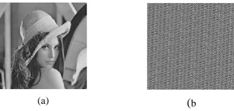
Arnold transform is commonly known as cat face transform. Apply Arnold transform in digital image, so it can change the layout of gray values by change the coordinates of pixels. Seen the digital image as a NN matrix, then can achieve image pixels scrambling by formula [9]:
) 1 ( mod
2 1
1 1
N Y
X Y
X
n n
Where (X,Y) is the location coordinates of the original image pixels, and (Xn,Yn)is the location coordinates of image pixel
that after transform [10]. Fig. 2shows the encryption image after applied Arnold transform over original image.
Encryption Compression Decompression
Decryption Arnold transformation
(
b)
(a)
Fig. 2 General flowchart of proposed system for encryption-compression image.
© 2016, IJCSMC All Rights Reserved 95
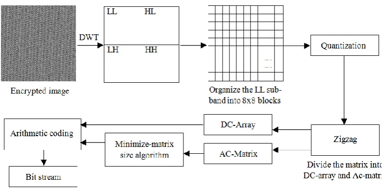
B. Hybrid DWT-DCT compression algorithm
The main objective of the presented hybrid DWT-DCT algorithm for image compression is to exploit the properties of both the DWT and the DCT (as illustrated in Fig. 3). The input image is first decomposed using DWT and then DCT is used to further enhance the compression performance.
1) Discrete Wavelet Transform
Discrete Wavelet transform (DWT) is the first phase in the proposed image compression algorithm, to produces four sub-bands (See Fig. 3). The top-left corner is called LL, represents low-frequency coefficients, and the top-right called HL consists of residual vertical frequencies. The bottom-left corner LH, and bottom-right corner HH are represents residual horizontal and residual vertical frequencies respectively. The high-frequency components (LH1, HL1 and HH1) are zero or insignificant. This reflects thefact that much of the important information is contained in the LL sub-band. For this reason all the high frequency domains are discarded in this research (i.e. set all values to zero) [11, 12]. In particular, the Daubechies wavelet transform has the ability to reconstruct approximately the original image. This property allows higher compression ratios; this is because high frequencies from the first level can be ignored without loss of accuracy [13, 14].
2) Discrete Cosine Transform
The LL sub-band partitioned into non-overlapped 88 blocks, each block is transformed by using two-dimensional DCT to produce de-correlated coefficients. Each
8
8
frequency domain consists of: DC-value at the first location, while other coefficients are called AC coefficients [15, 16]. The main reason for using DCT to split the LL sub-band into two different matrices is to produce a low frequency matrix (DC-Matrix) and a high-frequency matrix (AC-Matrix). After applying the two-dimensional DCT on each 88 block, each block quantized by the Quantization Matrix (QM) using dot-division-matrix with truncates the results. This process removes insignificant coefficients and increases the number of the zeros in the each block [17, 18]. QM computes as follows: even j i QM if j i Block odd j i QM if j i Block j i QM )) , ( ( 1 ) , ( )) , ( ( ), , ( ) ,
(
(2)
Where Block is represented block size and i, j=1,2,3…., Block.
Scale j I QM j i
QM(, ) ( , )*
(3)
In the above Equation (3), the factor (Scale) it is used to increase/decrease the values of the QM. Thus, image details is reduced in case of the factor Scale >1. There is no limited range for this factor, because this is depends on the DCT coefficients.
© 2016, IJCSMC All Rights Reserved 96
Each quantized
8
8
block is converted into one-dimensional array (i.e. the array contains 64 coefficients) by zigzag scan [14].Whereas, the first value transferred into new array called DC-Array, while others are 63 coefficients are stored to new matrix LLAC. Finally, the DC-Array is compressed by using Arithmetic coding. The Arithmetic coding is one of the importantmethods used in data compression method, especially this method used in JPEG2000. Arithmetic coding depends on (Low) and (High) equations to generate streams of bits [18].
Minimize-Matrix-Size Algorithm uses for codingLLAC Matrix. This algorithm applied on each three coefficients, to produce
single data. This means reduce each three columns to single coded array which is called Minimized-Array. However, the bit size for each data in the Minimized-Array increased. Fig. 4 shows converting three columns into one dimensional array [4, 19]. In above Fig. 4 (a) K1, K2 and K3 represents key for conversion. The following equation illustrates converting three data, to single data.
) (
) (
)
( 1 i 2 i 3 i
i K A K B K C
D (4)
Where i=1,2,3…,n.
The key values generated through random number generator and uses in coding and decoding. For example, assume we have the following array: [3 -9 0], Maximum value in the array=|-9|=M= 9, and Base Value=0.1; Key1= 0.8147, Key2=0.9058, and Key3=0.1270. The key generated once for all matrix data, after calculation, all coded data (Di) arranged together to be one-dimensional array (i.e. Minimized-Array). Before apply the Minimize-Matrix-Size algorithm, the algorithm computes the probability of the data for AC-matrix. These probabilities are called Limited-Data, which is used later in decompression stage [14]. The Limited-Data stored as additional information with compressed data. Fig. 5 describes Limited-Data computed from original matrix.
The Minimized-array contains positive and negative data, and each data size reached to 32-bit, these data can be compress by a coding method, but the index size reaches to 50% of compressed data size. The index data are used in decompression stage, therefore, the index data breakup into parts for easy compress. Each data partitioned into parts: 4-bit (i.e. each data in index may be breakup into six 4-bit data), and this process increase the probability of redundant data.
The final step of the compression algorithm is arithmetic coding, which is one of the important methods used in data compression; its takes a stream of data and convert it to a single floating point value. These values lie in the range less than one and greater than zero that, when decoded, return the exact stream of data. The arithmetic coding needs to compute the probability of all data and assign a range for each data (low and high) in order to generate streams of bits [18, 20].
© 2016, IJCSMC All Rights Reserved 97
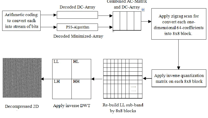
C. Decompression algorithm
The decompression algorithm represents reverse steps for the proposed image compression. Firstly, applied arithmetic decoding for decompress DC-array, Nonzero-array and Zero-array. Thereafter, nonzero-array and zero-array are combined together for reconstructing minimized-array. Secondly, using Parallel Sequential Search Algorithm (PSS-Algorithm), moreover, this algorithm represents inverse Minimize-Matrix-Size Algorithm for reconstructing AC-Matrix. PSS-Algorithm, estimates (Ai, Bi and Ci) by using (Di) with Key. Whereas, Ai, Bi and Ci are represents estimated columns for decompress AC-Matrix [17, 20, 21]. PSS-Algorithm can be illustrates in the following steps:
Step 1: PSS-Algorithm starts to pick first (P) data from the Limited-Data, and then these (P) data are connected with each other look like a network as shown in Fig. 6. In Fig. 6 (Column-1) data connected as a network with (Column-2) data, also (Column-2) is networking with (Column3). In another words, the searching algorithm computes all options in parallel. For example: A=[1 -1 0] , B=[-1 -2 0] and C=[3 --1 5], and P=3, according to Equation (4) (A),(B) and (C) computes 27 times. This means, all options computes in parallel and one option will be matched with the (Di), and (Ai), (Bi) and (Ci) in (Column-1), (Column-2) and (Column-3) represented decompressed data.
Initially, PSS algorithm starts with P=10 data from (Limited-Data(1…10.)) that used by the algorithm, these data are estimates three columns (A, B and C), as mentioned in Fig. 6 (a). Thereafter, the algorithm starts searching for original data (Ai, Bi and Ci) which is depends on compressed column (Di) and Key-values. The first iteration for the algorithm starts with matching selected (Di) with 10 outputs from PSS-algorithm (i.e. P=10, three columns = P3= 1000 data). In another words, Equation (4) executed 1000 times in parallel for finding original values for columns (A,B and C) as mentioned in Fig. 6 (b). If result unmatched, in this case the second option will be taken form (Limited-Data(11…20.)) (i.e. selecting another 10 data from Limited-Data transferred to Array1), while (Array2) and (Array3) are remains in same old options, if the processing still did not find the result, in this case (Array2=Array1) (i.e. transferred data from Array1 to Array2), then new processing starts. This process will continue until finding all original columns (Ai, Bi and Ci) in AC-Matrix.
© 2016, IJCSMC All Rights Reserved 98
(b)
data matched through PSS-AlgorithmStep 2: In this step decompressed AC-Matrix composed with each DC-value (i.e. DC-values from DC-array), then followed by zigzag scan to convert each 64-coefficients to 88 blocks. These blocks combined with each other to build LL sub-bands. Subsequently, applied inverse quantization (i.e. dot-multiplication), followed by inverse DCT on each 88 block. Finally, applied inverse DWT for obtaining 2D image. The decompression algorithm steps are showed in Fig. 7.
D. Image Decryption
At the receiver side, the original image can be reproduced by the inverse permutation (Arnold transform) with reverse order of this process as shown in Fig. 8.
Fig. 6
© 2016, IJCSMC All Rights Reserved 99 III.RESULTS AND DISCUSSIONS
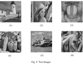
The current technique is applied on six grayscale images labelled image 1 to image 6 as shown in Fig. 9. Each of these images has size of (256×256 pixels) with 8-bit grey levels. It was implemented with (MATLAB 2012) package. The implementation was done on a PC (DELL laptop) with 2.1 GHz core 2 due processor and 2GB main memory running with windows 7 operating system.
The proposed work is analyzed by using various parameters like MSE (Mean Square Error), PSNR (Peak Signal to Noise Ratio) and CR (Compression Ratio) [22].
The mean square error (MSE) is used as metric to measure the distortion between original and reconstructed image [23]. The equation that evaluating the MSE is:
) 5 ( ,
)] , ( ) , ( [ *
1
1
2
1
M
y N
x
y x Irec y x I N
M MSE
where:
I : is the original image. Irec: is the reconstructed image.
(1) (2) (3)
(4) (5) (6)
Fig. 9 Test Images (b) (a)
© 2016, IJCSMC All Rights Reserved 100 M: the height of the image.
N: the width of the image.
x and y: row and column numbers.
The peak signal to noise ratio (PSNR) , in decibels (dB), can be evaluated as follows [24]:
) 6 ( ,
] / ) [( log .
10 10 P 2 MSE
PSNR ix
where Pix is maximum possible pixel value, e.g. 255 in an 8-bit grey-level image.
Compression Ratio (CR) refers to ratio of the size of an original image to the size of reconstructed image. It is defined as follows [22]:
) 7 (
rec
I I
CR
In our work, we evaluate different systems as described below:
System1 uses our propose work.
System2 uses standalone DCT in compression-decompression stage to encrypted image.
System3 uses standalone DWT in compression-decompression stage to encrypted image.
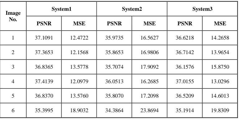
To test performance our system compared with other systems, we use different criteria such as MSE, PSNRandCR. The values of PSNR and MSE are compared in different systems, as shown in Table 1.
Fig 10 shows the PSNR values of six encrypted images for average compression ratio of 96% by System1, System2 and System3.
Image No.
System1 System2 System3
PSNR MSE PSNR MSE PSNR MSE
1 37.1091 12.4722 35.9735 16.5627 36.6218 14.2658
2 37.3653 12.1568 35.8653 16.9806 36.7142 13.9654
3 36.8365 13.5778 35.7074 17.9092 36.1576 15.8750
4 37.4139 12.0979 36.0513 16.2685 37.0155 13.0296
5 36.8370 13.5760 35.8070 17.2098 36.5209 14.6013
6 35.3995 18.9032 34.3864 23.8694 35.1914 19.8309
TABLE 1
© 2016, IJCSMC All Rights Reserved 101
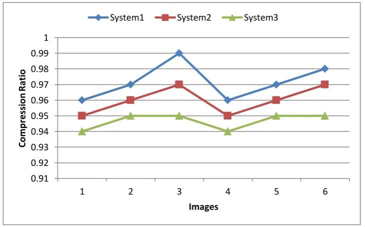
Similarly, Fig. 10 shows the compression ratio of six encrypted images for average PSNR of 32 db, when compressed by System1, System2 and System3.
Fig. 10 PSNR of images for System1, System2 and System3.
Fig. 11 CR of images for System1, System2 and System3. 0.91
0.92 0.93 0.94 0.95 0.96 0.97 0.98 0.99 1
1 2 3 4 5 6
C
o
m
p
res
si
o
n
R
at
io
Images
System1 System2 System3
32 33 34 35 36 37 38
1 2 3 4 5 6
P
SN
R
(d
b
)
Images
© 2016, IJCSMC All Rights Reserved 102 IV.CONCLUSIONS AND FUTURE WORKS
In this paper, an efficient image encryption and compression system is designed using image transformation. An From the experimental results it is evident that, the proposed system technique gives better performance compared to other traditional systems techniques. In another meaning, the value of PSNR, CR are high and the value of MSE is low that means our technique is effective. Also the results demonstrate that for test images, the loss of information is less hence the quality is better. In future, the technique can be extended by applying different transforms on color image. High performance compression algorithms may be developed and implemented using neural networks and soft computing.
R
EFERENCES[1] H. Zhu, C. Zhao, and X. Zhang, "A Novel Image Encryption–Compression Scheme Using Hyper-Chaos and Chinese Remainder Theorem," Signal Processing: Image Communication, vol. 28, Issue 6, pp. 2992–3006, July 2013.
[2] M. Johnsonand D. Schonberg," On Compressing Encrypted Data," IEEE Transactions On Signal Processing, Vol. 52, No. 10, pp. 670–680, Oct. 2004.
[3] X. Zhang, " Lossy Compression and Iterative Reconstruction for Encrypted Image," IEEE Transactions On Information Forensics And Security, Vol. 6, No. 1, pp. 53–58, March 2011.
[4] R. C. Gonzalez and R.E. Woods, Digital Image processing, 3rd ed, Pearson Prentice Hall, 2008.
[5] W. Liu, L. Dong, and Q. Yao, "Efficient Compression of Encrypted Grayscale Images," IEEE Transactions On Image Processing, Vol. 19, No. 4, pp. 1097–1102, April 2010.
[6] J. Zhou, and Y.Y. Tang, " Designing an Efficient Image Encryption-Then-Compression System via Prediction Error Clustering and Random Permutation," IEEE Transactions On Informations Forensics And Security, Vol. 9, No. 1, pp. 39– 50, Jan. 2014.
[7] M. M. Khudhair, " An Efficient Image Encryption Technique by Using Cascaded Combined Permutation," International Journal of Computer Science and Information Security (IJCSIS), Vol.14, No. 6, pp. 576-588, 2016.
[8] S. Li, C. Li, G. Chen, N. G. Bourbakis, and K. T. Lo, "A General Quantitative Cryptanalysis of Permutation-only Multimedia Ciphers Against Plaintext Attacks," Signal Processing: Image Communication, Vol. 23, pp. 212–223, March 2008.
[9] B. Wang, J. Ding, Q. Wen, X. Liao, and C. Liu, " An Image Watermarking Algorithm Based On DWT DCT and SVD,"
IEEE International Conference, Network Infrastructure and Digital Content, pp. 1034–1038, Dec. 2009.
[10] G. Chen, Y. Mao, and C. K. Chui, " A Symmetric Image Incryption Scheme Based on 3D Chaotic Cat Maps," Chaos, Solitons and Fractals, Vol. 21, Issue 3, pp. 749–761, July 2004.
[11] K. S. Thyagarajan, Still Image and Video Compression with Matlab, John Wiley & Sons, Inc., Hoboken, New Jersey, 2011. [12] M.C. Stamm and K. J. R. Liu, " Wavelet-Based Image Compression Anti-Forensics," In Proceedings of IEEE 17th
international conference on image processing, Hong Kong, pp. 1737–1740, Sep. 2010.
[13] M. Antonini, M. Barlaud, and I. Daubechies, "Image Coding Using Wavelet Transform," IEEE Transactions on Image Processing, Vol. I , No. 2, pp. 205–220, April 1992.
[14] T. Acharya, and P. S. Tsai, JPEG2000 Standard for Image Compression: Concepts, Algorithms and VLSI Architecture, New York, John Wiley & Sons, 2005.
[15] K. R. Rao, and P. Yip, Discrete Cosine Transform: Algorithms, Advantages, Applications, San Diego, Academic Press, 1990.
[16] D. Zhao, W. Gao, and Y. K. Chan, "Morphological Representation of DCT Coefficients for Image Compression," IEEE
Transactions on Circuits and Systems FOR Video Technology, Vol. 12, No. 9, pp. 819–823, Sep. 2002.
[17] F. Huang, J. Huang, and Y. Q. Shi, " Detecting Double JPEG Compression With the Same Quantization Matrix," IEEE Transactions on Information Forensics and Security, Vol. 5, No. 4, pp. 848–856, Des. 2010.
[18] K. Sayood, Introduction to Data Compression, 4th ed, Academic Press, Morgan Kaufman Publishers, 2012.
[19] S. Singh, V. Kumar, and H. K. Verma, "DWT–DCT Hybrid Scheme for Medical Image Compression," Journal of Medical Engineering & Technology, Vol. 31, No. 2, pp. 109–122, April 2007.
[20] M.M. Siddeq, and G. Al-Khafaji, " Applied Minimized Matrix Size Algorithm on the Transformed Images by DCT and DWT used for Image Compression," International Journal of Computer Applications, Vol. 70, No.15, pp. 33–40, May 2013.
[21] P. Y. Chen, and J. Y. Chang, " An Adaptive Quantization Scheme for 2-D DWT Coefficients," International Journal of Applied Science and Engineering, Vol. 11, No.1, pp. 85–100, 2013.
[22] J. Singh, and P. Kaur, " Image Encryption and Compression System Using Haar, Daubechies and Coiflet Wavelets," International Journal of Computer Science Engineering and Information Technology Research, Vol. 5, Issue 5, pp. 17–26, Oct. 2015.
[23] Y. K. Chen, F. C. Cheng, and P. Tsai, "A Gray-Level Clustering Reduction Algorithm with the Least PSNR," Expert Systems with Applications 38, pp. 10183–10187, 2011.