Article
Mapping and Navigation for Indoor Robots under
ROS: An Experimental Analysis
Bruno M. F. da Silva1,2 , Rodrigo S. Xavier1,2and Luiz M. G. Gonçalves1,3*
1 Natalnet Associate Laboratories, Federal University of Rio Grande do Norte, Campus Universitário,
59078-970, Natal, Brazil;
2 School of Sciences and Technology, Federal University of Rio Grande do Norte, Campus Universitário,
59078-970, Natal, Brazil; [email protected], [email protected]
3 Department of Computer Engineering and Automation, Federal University of Rio Grande do Norte,
Campus Universitário, 59078-970, Natal, Brazil [email protected]
1
2
3
4
5
6
7
8
9
10
11
12
* Correspondence: [email protected]; Tel.: +55-84-3215-3771
Abstract: Since it was proposed,the Robot OperatingSystem(ROS) has fosteredsolutions for variousproblemsinroboticsintheformofROSpackages.OneoftheseproblemsisSimultaneous LocalizationandMapping(SLAM),aproblemsolvedbycomputingtherobotposeandamapofits environmentofoperationatthesametime. Theincreasinglyavailabilityofrobotkitsreadytobe programmedandalsoofRGB-DsensorsoftenposethequestionofwhichSLAMpackageshould beusedgiventheapplicationrequirements. When theSLAMsubsystemmustdeliverestimates forrobotnavigation,asisthecaseofapplicationsinvolvingautonomousnavigation,thisquestion isevenmorerelevant.ThisworkpresentsanexperimentalanalysisofGMappingandRTAB-Map, twoROScompatibleSLAMpackages,regardingtheirSLAMaccuracy,qualityofproducedmaps anduseofproducedmapsinnavigationtasks. Ouranalysis aimsgroundrobotsequippedwith RGB-Dsensorsforindoorenvironmentsandissupportedbyexperimentsconductedondatasets fromsimulation,benchmarksandfromourownrobot.
Keywords: ROS;SLAM;RGB-Dsensors; experimentalanalysis
13
1. Introduction 14
With technological advances in sensing devices and computing the problem known as 15
Simultaneous Localization and Mapping (SLAM) [1–4] has been one of the most worked problems by 16
the Robotics research community in the last decade, which has produced several contributions [5–9]. 17
To solve the SLAM problem, a map of the surroundings of a robot should be incrementally constructed 18
at the same time that the robot pose (localization and orientation) is continuously estimated with 19
respect to this map. Since the navigation of the robot in an environment involves knowing its own 20
location and those of its goals, determining the best solutions for SLAM is considered an important 21
step towards enabling mobile robots to operate without human intervention. 22
The interest for SLAM has increased due in large part to the Robot Operating System (ROS) [10], 23
which has been proposed to facilitate the development of software for robotics and has become the 24
de factostandard robotics middleware. Facilities like offering inter process/inter machine message 25
passing mechanisms and hardware abstraction for handling data from robot sensors and controllers 26
explains why ROS has been widely adopted in robot research and industry [11]. ROS is open source as 27
well, which makes its development reach more visibility. 28
Nevertheless, estimates for the pose of a robot and the mapping of its environment of operation, 29
alone, are not sufficient for allowing the robot navigation. Besides offering SLAM estimates with the 30
lowest possible errors, a robot must plan a trajectory from its location to goal locations using a suitable 31
map representation, such as occupancy grid [1] and then execute the necessary commands to traverse 32
the planned route. 33
The broad adoption of ROS by the community has contributed substantially to the development 34
of novel approaches on both SLAM [5–9,12–17] and robot navigation [18]. The solutions are available 35
as ROS packages, a high level of abstraction software ready to be used on any ROS compatible robot. 36
It is often the case that roboticists and mainly non roboticists are posed with the choice of which 37
SLAM algorithm should be employed on a given application in view of their requirements. Choices 38
like this have become common because of the increasingly availability of programmable robot kits like 39
the Turtlebot1and RGB-D cameras, which are a class of cameras that has enough accuracy for indoor, 40
small scale applications and include, for example, the Microsoft Kinect, Intel RealSense, ZED stereo 41
camera [19] and the recently launched SVPRO 3D VR. Methods for rapidly and easy calibrating and 42
using these cameras have also become available [20]. 43
Considering the vast availability of ROS packages for SLAM, our work aims to to provide a 44
preliminary guidance in order to assist beginners and experienced roboticists on the selection of an 45
adequate ROS compatible SLAM package. We aim to support the development of applications for 46
indoor environments using ground, mobile robots equipped with a RGB-D camera solution. For 47
this, we experimentally analyze the GMapping [12] and RTAB-Map [9] ROS packages taking into 48
consideration the SLAM accuracy of the algorithms, the quality of the grid maps produced as outputs 49
and how well these grid maps are used in navigation tasks. In our analysis, we focus on practical 50
aspects of the algorithms and relate their performance with their inner workings and configurable 51
parameters. To support our analysis, we conduct experiments on datasets from simulation, SLAM 52
benchmarks [21] and on real robot sensory data collected at the facilities of our university. So, the main 53
contribution of this work can be understood as being twofold. The first one is to analyze the main ROS 54
packages that deal with simultaneous localization and mapping and the second contribution relies on 55
the production pf our own dataset that can be used for this kind of evaluation, for existing or further 56
algorithms. 57
The remaining of this paper is organized as follows. Section2lists works related to SLAM and 58
ROS implementation of SLAM algorithms, along with other experimental evaluation of ROS SLAM 59
packages. Section3briefly describes the analyzed SLAM algorithms, whereas Section4provides the 60
details on how the evaluation was carried out. Section5explains our analysis in light of the results of 61
the performed experiments. Finally, we conclude the work with Section6. 62
2. Related Works 63
Since its proposition, 10 years ago, the wide adoption of ROS has boosted research and 64
development of robotics applications. Researches related to ROS include, to name a few, using 65
robots as a service [22–24], easing development of applications using robots [25], leveraging robotics 66
for education [26], developing robots for telepresence [27] and enabling knowledge transfer between 67
robots [28]. 68
Variations of SLAM are used in the above applications and it is considered nowadays, actually, as 69
a well-studied problem. Its theoretical background, foundations and sensor agnostic formulations are 70
available in tutorial papers [2,3,29] and text books [1,4]. In general, SLAM algorithms must be able to 71
associate sensor data gathered from distinct time steps and also current sensor data with current map 72
data. This last ability is known in the literature asloop closing[2,3], and is of uttermost importance for 73
any robotic platform to operate. 74
Algorithms relying on sensor modalities such as lasers [30], monocular cameras [31,32], stereo 75
cameras [33,34] and RGB-D cameras [35] have been designed and validated for indoor, outdoor, 76
structured and non-structured scenarios. Nonetheless, SLAM still has various open issues [36], mainly 77
because a general purpose solution that works with all sensors and all types of environments is not 78
available, yet. 79
As a consequence, a considerable number of ROS compatible SLAM systems is present in the 80
robotics literature [5–9,12–17]. Each of these solutions is designed based on its own mathematical 81
formulation that allows it to work in a specific combination of application requirements, such as 82
number and type of sensors, degrees of freedom (DoF) of the robot movement and characteristics of 83
the operation environment. In line with this and according to the used sensor type, we can divide ROS 84
SLAM systems in two main categories: lidar and vision based. 85
Among the lidar based ROS systems, we can cite GMapping [12], tinySLAM [13], Karto SLAM 86
[5], Lago SLAM [6], Hector SLAM [14] and Google Cartographer [8]. In practice, lidar based SLAM 87
algorithms work by fusing laser scans with robot odometry [5,6,8,12,13] or with IMU [14]. The 88
underlying formulation of these approaches assumes a planar lidar mounted on a robot moving on 89
a 2D plane, which limits the estimated robot poses to 3 DoF (2D position and an orientation angle). 90
Albeit, an algorithm as the Hector SLAM is able to estimate 6 DoF poses (3D position and three rotation 91
angles around theX,YandZaxis) if an IMU is available. GMapping and tinySLAM solve SLAM 92
calculating the probability density function of the robot pose and perceived map given laser scans and 93
robot odometry. The computation is implemented with a particle filter [1], which maintains a set of 94
particles that are representations of robot pose and environment map. These particles are continuously 95
sampled during the process. Lago SLAM, Karto SLAM and Google Cartographer estimate the same 96
probability density function, but solves an optimization problem on graphs in which the vertices are 97
robot poses and the edges are rigid transformations relating pairs of robot poses [29]. The Hector 98
SLAM follows an alternative approach which optimizes the robot pose that best fits the laser scan 99
endpoints within the map using gradient descent for error minimization. 100
RGB-D SLAM [7], LSD SLAM [15], ORB SLAM [16], ORB SLAM 2 [17] and RTAB-Map [9] can be 101
cited as relevant works on vision based ROS systems. Systems from this class are based on a real-time 102
3D reconstruction framework known as visual odometry [37], which in turn was originated from the 103
projective geometry theory [38]. To compute 6 DoF robot poses and environment maps, the algorithms 104
use images from a single camera [15–17], stereo camera [9,17] or from RGB-D camera [7,9,17]. Camera 105
poses are then estimated from image keypoints such as SIFT [39], SURF [40] or ORB [41]. As more 106
recently proposed, they can also be estimated directly from image intensity [15,42]. Together with 107
loop closing (detecting when a previously mapped location is being revisited) and the optimization 108
back-end [9,16,17,43], visual odometry is an important component in vision based SLAM. Hence it is 109
worth mentioning that there are also visual odometry systems compatible with ROS [42,44,45]. 110
A clear advantage of lidar based approaches is the fact that ROS packages of this class produce a 111
2D representation of the environment known as occupancy grid [1], which in general is not available 112
from the visual SLAM counterpart. Occupancy grid is essential for robot navigation, since path 113
planning algorithms use it as one of the input data along with the starting and final positions. Because 114
of the prohibitive costs of lidars, especially for low cost applications, one solution is to emulate a 115
laser scanner with an RGB-D sensor. GMapping, Hector SLAM and RTAB-Map are examples of ROS 116
systems that support an RGB-D sensor emulating a laser scanner, although with varied rates of success 117
[46]. 118
Empirical comparisons of ROS SLAM systems have been proposed in the robotics literature 119
[46–49]. In general, these works aim to provide guidance for roboticists that seek for the best SLAM 120
solution according to different application requirements. For example, Santos et al. [47] evaluate lidar 121
based SLAM algorithms for robot search and rescue competition. Monocular visual SLAM solutions 122
are evaluated in the work of Buyval et al. [48] whereas the work of Ibragimov and Afanasyev [49] 123
experiments with monocular, stereo and RGB-D algorithms. 124
In our previous work [46], we experimentally evaluatetd some ROS SLAM algorithms that can 125
Firstly, we focus our analysis on the best two algorithms: GMapping, a lidar based solution that can be 127
employed with a RGB-D sensor and the RTAB-Map, which is a visual solution supporting various 128
configurations. Secondly, the SLAM accuracy of the selected systems is assessed on a commonly used 129
benchmark [21]. Thirdly, the two solutions are evaluated on both simulation datasets, from Gazebo 130
[50] and on our own real data. In comparison to the data used in our previous work, the operation 131
environment of the experiments in this work is larger in size, distance travelled and has different data 132
capturing conditions. Lastly, since the two selected algorithms produce occupancy grids, we evaluate 133
the resulting grids and whether the quality of produced grids are suited for robot navigation. 134
3. Robot Mapping with ROS 135
ROS [10,51] is a middleware for robotics that offers hardware abstraction and inter-process 136
communication mechanisms. Modules from robot software which are commonly used in different 137
applications can be reused thanks to its underlying architecture. 138
More specifically, each running process in the ROS is called a node. Each node is able to 139
communicate with another node by a publish/subscribe message passing scheme: nodes that subscribe 140
on a topic receive the corresponding message whenever any node on the system publishes a message 141
on that topic. This mechanism allows the design of robot software composed of independent, 142
asynchronous and distributed programs that talk to each other, as is the case of software involved in 143
autonomous mapping for robotics. Also, ROS keeps all transformations between the reference frames 144
involved in the distributed system in a tree structure called transformation tree (tf tree). 145
For an algorithm to compute a solution for SLAM, it must estimate the robot pose xt, 146
parameterized by a 2D or 3D position and one or three rotation angles, according to the DoF of 147
the robot movement. It must also estimate a mapmt, which is generally given as an occupancy grid 148
but may also be represented by a 2D or 3D point cloud. This is performed by processing sensor 149
measurementsztand odometry readingsut, with all of these quantities indexed by a time stept. 150
In a ROS system solving the SLAM problem, a node computes the current robot pose and the 151
map by subscribing to topics related to the required sensor measurementsztand odometry readings 152
ut. Each time a new sensor measurement or odometry reading is published by the respective sensor 153
nodes, the subscribed node gets notified and thus it receives a message consisting of sensor data or 154
odometry displacement. These messages are in turn processed by the algorithm, producing the most 155
recent estimate for the robot localizationxtand mapmtof its environment. 156
The ROS subsystem responsible for robot navigation [18] takes as input the map produced by 157
SLAM, the robot location and a goal location. Then, a planned trajectory is forwarded to the ROS nodes 158
that are responsible for the robot controllers, which then drive the robot towards its goal location. For 159
this to be possible, the map must be a in a suitable representation for ground robot navigation called 160
occupancy grid [1]. An occupancy grid is a planar 2D grid formed by a set of square cells. Each cell 161
of the grid has a probability value informing if the cell is navigable or not by a robot. Additionally, 162
reactive nodes perceive the environment using data from the available sensors in order to detect 163
dynamic objects that are not present in the grid maps. In doing so, routes can be re-planned whenever 164
is the case that dynamic objects appear in front of the robot while it is moving to its goal location. 165
3.1. GMapping 166
GMapping [12] is a planar (2D) SLAM algorithm that relies on the robot odometry and on 167
measurements that come from range sensors (e.g. sonars and lasers) to estimate both the robot pose 168
and the map in which the robot is operating, which is represented as an occupancy grid. 169
Following the well known Bayesian approach [1] to fuse pose transitions and sensor measurements 170
in a probabilistic framework, the algorithm solves SLAM by utilizing a Rao-Blackwellized Particle 171
Filter. Equation1shows the sought posterior probabilityp(xt,mt|zt,ut)after being factorized by a 172
p(xt,mt|zt,ut) =p(xt|zt,ut)p(mt|xt,zt) (1)
In Equation1, the posterior probability of a robot posextand mapmtgiven sensor measurements 174
ztand odometryutis shown as a product of two other probabilities: the probabilityp(xt|zt,ut)of 175
having posextgiven measurementsztand odometryuttimes the probabilityp(mt|xt,zt)of having a 176
mapmtgiven robot posextand measurementszt. 177
In a particle filter, hypothesis for the robot pose and the map of its environment are kept in a set 178
of particles. Each particle<xi,mi,wi >of the set{<x1,m1,w1>, ...,<xN,mN,wN >}has a history 179
of past robot posesxi, a map computed from this historymiand a weightwi. The particle weight is 180
a probability value that informs how likely the particle represents the pose history and map given 181
odometry and sensor measurements. 182
The challenge is then how to sample each particle<xi,mi,wi >in a way that truly represents the 183
robot belief about its pose and computed map. For this, GMapping relies on robot odometry and scan 184
matching (registration between consecutive laser scans) to estimate the parameters of a probability 185
density function from which the particle set will be generated in each iteration of the filter. In doing so, 186
the number of particlesNneeded for accurate SLAM estimation is drastically reduced, which in turn 187
also reduces the computational cost involved in the process. The particle depletion problem [12], a 188
situation inherent to particle filters in which particles with a high weight can be discarded, is avoided 189
by the algorithm. To comply with this, particles are resampled only if an estimated number of effective 190
particlesNe f f is below a prespecified threshold. 191
3.1.1. GMapping ROS Implementation 192
The GMapping ROS implementation is composed of a single ROS node calledslam_gmapping. 193
This node subscribes to ascantopic with sensor data andtftopic with odometry data. Whenever the 194
node receives a message from these topics, it publishes messages in the topicsmap(which publishes 195
the updated occupancy grid) and updates the transformation from themapreference frame to the 196
odom(odometry) reference frame in the robottf_tree. Table1lists the relevant topics published or 197
subscribed by theslam_gmappingROS node. 198
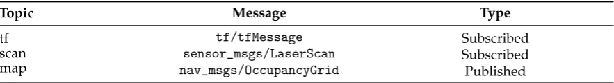
Table 1.List of relevant published/subscribed topics for the GMapping ROS package.
Topic Message Type
tf tf/tfMessage Subscribed
scan sensor_msgs/LaserScan Subscribed
map nav_msgs/OccupancyGrid Published
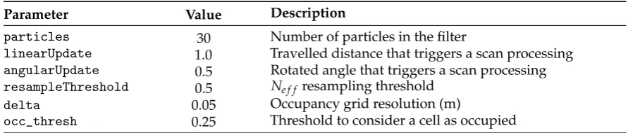
ROS allows online parameter tuning of the algorithms. For GMapping, a not exhaustive list from 199
the available parameters2is given on Table2, along with the values used in our experiments. 200
Table 2.List of relevant parameters for the GMapping ROS package.
Parameter Value Description
particles 30 Number of particles in the filter
linearUpdate 1.0 Travelled distance that triggers a scan processing
angularUpdate 0.5 Rotated angle that triggers a scan processing
resampleThreshold 0.5 Ne f f resampling threshold
delta 0.05 Occupancy grid resolution (m)
occ_thresh 0.25 Threshold to consider a cell as occupied
3.2. RTAB-Map 201
RTAB-Map (Real Time Appearance Based Mapping) [9] is a ROS compatible visual SLAM 202
algorithm that works with a stereo or RGB-D camera. The robot pose estimated by RTAB-Map 203
has 6 DoF, which makes it suitable for non-planar (e.g. drones) robots. Originally designed as visual 204
loop closing algorithm based on a memory management mechanism [52], the ROS package has evolved 205
to incorporate various functionalities related to SLAM. With these functionalities, RTAB-Map can 206
combine visual SLAM with input data from other sensors such as IMU, lidar, robot odometry and an 207
emulated laser scanner (from RGB-D data). 208
The visual processing algorithm of RTAB-Map is a feature based implementation of a visual 209
odometry [37] front-end with a pose graph optimization [29] back-end. This architecture has been 210
used in a number of visual SLAM algorithms [7,16,17,32]. 211
Visual odometry work as follows. In each input image, features (configurable as 212
GoodFeaturesToTrack [GFTT] [53], SURF [40], BRIEF [54], etc.) are extracted and matched against those 213
in the previous image. For this, RTAB-Map can use optical flow or matching by distance minimization 214
between descriptor vectors. Then, the global 3D coordinates associated with the tracked features are 215
used as input in a perspective-n-point algorithm [37], which allows to estimate the camera pose in the 216
reference frame of the 3D coordinates. Whenever the number of keypoint matches falls below a fixed 217
threshold, an image is detected as a keyframe and a node is added to a graph of keyframe poses. The 218
estimated camera pose is continuously optimized by bundle adjustment [38] along with the camera 219
pose of the last keyframes and the 3D coordinates of keypoints visible in these keyframes. Camera 220
pose estimation is robust to dynamic scenes, since a feature prediction scheme is employed on the 221
process. 222
A visual memory formed by quantized keypoint descriptors (bag of words) [52] is managed by the 223
algorithm to allow detection of revisited places. For this to be executed with real-time performance, the 224
memory is partitioned in short term memory (STM), working memory (WM) and long term memory 225
(LTM). The STM is composed by the last keyframes and bag of words descriptor associated with each 226
of them; the WM is formed by recent keyframes excluding those of the STM; finally, the LTM is formed 227
by keyframes that correspond to locations not recently visited. Each memory partition has a fixed 228
size. The algorithm manages which keyframes should be moved in and out the STM, WM and LTM 229
according to loop detection. 230
To detect loop closures, the bag of words of the current image is compared to those of the nodes 231
in WM. If the algorithm detects a loop closure, a graph optimization routine is triggered, optimizing 232
the node with the current camera position and those kept in the WM. 233
RTAB-Map is flexible and configurable in the sense that it allows the integration of robot odometry 234
and laser odometry to replace visual odometry. If it is the case that a lidar is available, scan matching 235
transformation is estimated between pairs of point clouds by the ICP algorithm [55] or between the 236
scan and the map. 237
As the representation for the produced map, the algorithm outputs dense 3D point clouds of the 238
3.2.1. RTAB-Map ROS Implementation 240
RTAB-Map is implemented on ROS with a main node calledrtabmap. The main node handles 241
node creation and visual memory management. Odometry is computed by the nodesrgbd_odometry, 242
stereo_odometryoricp_odometry, depending on the category of desired odometry computation. 243
The configured odometry also imposes which topics (Table3) will be required by the main node. The 244
main node publishes the current map in the topicgrid_map(occupancy grid map) or in the topic 245
cloud_map(dense point cloud). In addition, the estimated pose is set as the relative transformation 246
from themapreference frame to theodomreference frame in thetf_treeof the robot. 247
Table 3.List of relevant published/subscribed topics for the RTAB-Mapping ROS package.
Topic Message Type
odom nav_msgs/Odometry Subscribed
rgb/image sensor_msgs/Image Subscribed
rgb/camera_info sensor_msgs/CameraInfo Subscribed
depth/image sensor_msgs/Image Subscribed
scan sensor_msgs/Image Subscribed
grid_map nav_msgs/OccupancyGrid Published
cloud_map sensor_msgs/PointCloud2 Published
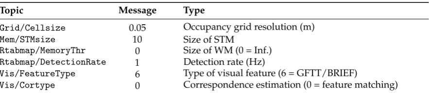
We configure RTAB-Map to use visual odometry only. Given its flexible nature, RTAB-Map has a 248
considerable list of adjustable parameters3. Table4shows a list of relevant parameters and the values 249
used in the experiments according to our description of the algorithm. 250
Table 4.List of relevant parameters for the RTAB-Mapping ROS package.
Topic Message Type
Grid/Cellsize 0.05 Occupancy grid resolution (m)
Mem/STMsize 10 Size of STM
Rtabmap/MemoryThr 0 Size of WM (0 = Inf.)
Rtabmap/DetectionRate 1 Detection rate (Hz)
Vis/FeatureType 6 Type of visual feature (6 = GFTT/BRIEF)
Vis/Cortype 0 Correspondence estimation (0 = feature matching)
4. Analysis Methodology 251
In this section, we explain the methodology employed to analyze the selected ROS packages for 252
the task of indoor mapping and navigation. A description of the used materials and datasets utilized 253
in the experiments is given along with the reasons that motivate each of them. Also, we describe the 254
metrics used to evaluate the selected algorithms quantitatively and qualitatively. Finally, we list which 255
functionalities we find important for the task of robotic mapping and navigation and the experiments 256
carried out to assess whether and how each algorithm implements these features. 257
4.1. Datasets 258
Among many other tools, ROS provides the functionality to record multiple streams of data in a 259
file format called ROS bag. A ROS bag is a synchronized collection of sensor data (odometry, color and 260
depth images, etc.) that can be played as if the recorded data streams were being collected online. 261
In the following, we list each category of ROS bag used in the experiments. 262
4.1.1. Gazebo Simulation Datasets 263
A common procedure in robotics is to evaluate algorithms in simulators before employing robotic 264
platforms to operate in real world scenarios. Taking advantage of the simulation tools available on 265
ROS, we evaluate the selected algorithms on 3D virtual environments generated by computer graphics. 266
This evaluation can make explicit certain properties related to the mapping process that we would not 267
have access otherwise (e.g. the exact distance travelled by a robot). 268
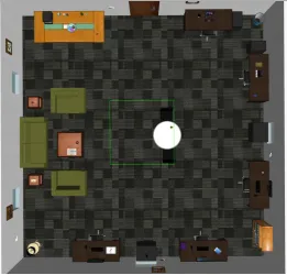
Figure 1. Top view of the virtual environment in Gazebo simulator from which we generated two datasets.
Hence, we use the Gazebo simulator [50] and a publicly available virtual environment [56] to 269
analyze the selected mapping algorithms. 270
Two different datasets were generated in the virtual environment shown on Figure1. The selected 271
virtual environment is a single room mimicking an office, in which there are textured 3D objects such 272
as couches, desks, bookshelves, etc. 273
A simulated model of the Turtlebot 2 robot was teleoperated to travel the virtual environment 274
performing a short trajectory, which generated the dataset sim_shortand a long trajectory, which 275
generated the dataset:sim_long. 276
4.1.2. TUM RGB-D Datasets 277
The well known TUM RGB-D datasets [21] offers RGB-D data synchronized with ground truth 278
along with assessment tools in a complete benchmark package. It allows a quantitative evaluation of 279
RGB-D SLAM algorithms, since statistics of error metrics can be calculated when using the benchmark. 280
We select the four following sequences from the available datasets:fr2/pioneer_360,fr2/pioneer_slam, 281
fr2/pioneer_slam2andfr2/pioneer_slam3. The version of these datasets in ROS bag format has data 282
streams of a Pioneer mobile robot equipped with a Kinect RGB-D camera and a SICK laser scanner. 283
The data was captured with the robot being tele-operated to navigate an open warehouse having 284
some scattered objects. For this reason, these datasets are compatible with RTAB-Map and with the 285
GMapping algorithm, which assumes a robot performing only 2D planar motions as is the case of the 286
discussed image sequences. However, it should be noted that the ROS bag files are not compatible 287
with RTAB-Map because the recorded transformation tree is incomplete. As a consequence, we had to 288
technical issue does not change the algorithm and is mentioned here to possibly guide users having 290
this same problem. 291
4.1.3. ROS Bags Collected at Natalnet-UFRN 292
We are interested in analyzing the result of the GMapping and RTAB-Map ROS packages for 293
datasets collected at facilities of the Natalnet Laboratory from Federal University of Rio Grande do 294
Norte (UFRN). 295
For this, we operate a Turtlebot 2 equipped with a Kinect RGB-D camera with a joystick. The 296
robot moves around the facilities recording in a ROS bag file data streams with registered color/depth 297
images (RGB-D data), robot odometry, an emulated laser scan (computed from depth data) and the 298
robottf_tree 299
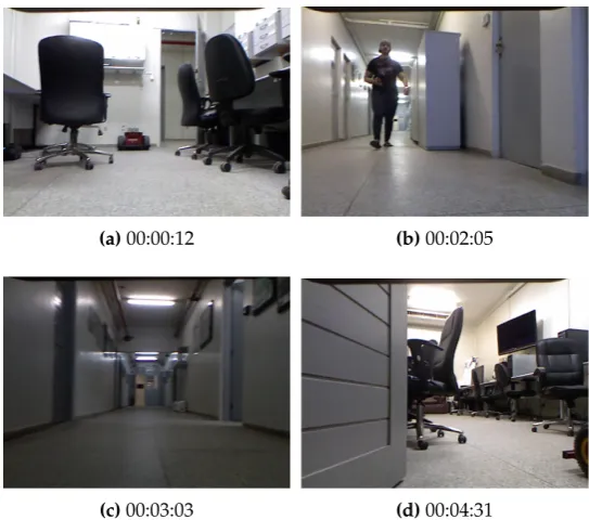
(a)00:00:12 (b)00:02:05
(c)00:03:03 (d)00:04:31
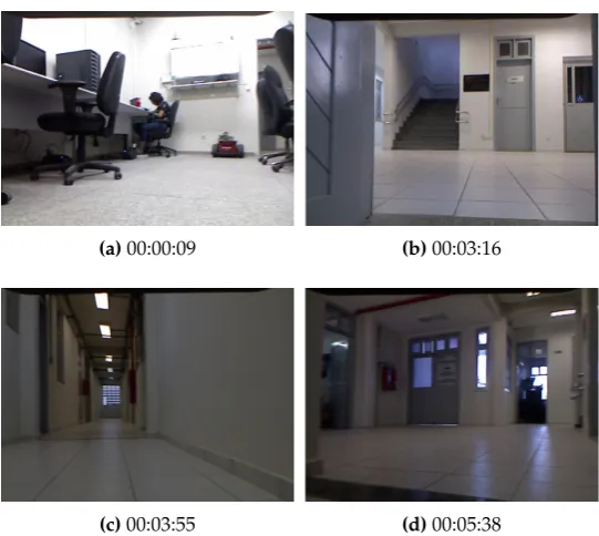
(a)00:00:09 (b)00:03:16
(c)00:03:55 (d)00:05:38
Figure 3.Images from theDCA_completedataset. Also indicated is the correspondent timestamp in which each image was captured.
Two datasets were collected:Natalnet-DCA_corridorandNatalnet-DCA_complete. Images depicting 300
the mapped environment are shown in Figure2and Figure3respectively. In both datasets, the robot 301
starts from our research laboratory and travels throughout the department corridors, finishing its 302
trajectory at our laboratory. 303
During the data collection process, the scenes captured have different illuminations conditions, 304
mixed amount of texture and also persons walking in front of the robot. All these conditions impose 305
difficulties that the mapping algorithms must overcome. 306
4.2. SLAM Performance 307
From Gazebo simulation and TUM RGB-D datasets, a quantitative evaluation of the accuracy of 308
SLAM algorithms can be carried out. This is possible because the estimated data can be compared 309
against a ground truth. 310
Accordingly, the maximum and root mean squared (RMSE) Absolute Trajectory Error (ATE), a 311
standard metric for SLAM accuracy [21], are computed for each dataset of these simulations and TUM 312
RGB-D categories. The ATE metric measures the misalignment between the ground truth trajectory 313
and the robot trajectory computed by a SLAM algorithm. 314
4.3. Mapping Performance 315
Both GMapping and RTAB-Map produces as output a map that is suitable for robot navigation 316
known as an occupancy grid [1]. We evaluate qualitatively the quality of the maps produced by each 317
algorithm by visually inspecting if the results are consistent with the static portion of the environment. 318
4.4. Reuse of Grid Maps in Localization Only Mode 319
Our evaluation of the selected ROS algorithms for SLAM also involves how the produced grid 320
maps can be employed in robot navigation. Hence, we conduct an experiment assessing whether 321
the computed grid maps can be loaded by the robot to be reused in another mapping session. There 322
are two configurations for this scenario: 1. a SLAM algorithm loads a previously computed map, 323
a previously computed map in localization only mode i.e. the robot uses its sensors to localize itself 325
within the map with mapping capability disabled. 326
The advantage of the first configuration is the capability to extend the original map to include 327
non explored areas although with the risk of overwriting the map with wrong estimates. The second 328
configuration offers the possibility of robots with different sensors than those used on the map 329
construction to localize themselves within the map but they are only allowed to navigate in the original 330
mapped area. 331
4.5. System Configuration 332
The experiments were carried out using a laptop computer with an Intel Core i7-7500U 2.70Ghz 333
processor and 8 GB of RAM running Ubuntu 16.04 with ROS Kinectic. This computer was used to run 334
the ROS nodes responsible to collect the ROS bags of our datasets, process the operations commands 335
for the robot, execute the mapping algorithms and show the current state of the mapping process. 336
5. Experimental Analysis 337
This section shows results of the experiments carried out to evaluate GMapping and RTAB-Map 338
SLAM algorithms. An analysis of the algorithms is drawn based on their performance in relation to 339
SLAM accuracy, quality of the produced maps and aspects important to how the produced maps are 340
reused in navigation. We make available video sessions4of the system in execution, offering another 341
resource to follow our analysis. 342
5.1. SLAM Accuracy in Simulation 343
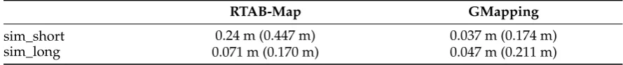
The SLAM accuracy of GMapping and RTAB-Map represented by the RMSE of the ATE for the 344
datasets from Gazebo simulation are shown on Table5. 345
Table 5. Absolute Trajectory Error (ATE) of the SLAM algorithms on datasets from simulation (maximum error is shown enclosed in parentheses).
RTAB-Map GMapping
sim_short 0.24 m (0.447 m) 0.037 m (0.174 m)
sim_long 0.071 m (0.170 m) 0.047 m (0.211 m)
In these datasets, GMapping presents a lower RMSE than RTAB-Map in bothsim_shortand 346
sim_longdatasets. We verified that this reflects the fact that GMapping uses an error free odometry: 347
Gazebo does not add noise to the actual synthetic robot trajectory when simulating this data. Also, since 348
RTAB-Map relies on appearance data rather than geometry data (as does GMapping), the computer 349
generated texture and lighting directly influence its performance. RTAB-Map has a better SLAM 350
performance onsim_longthan it has onsim_shortbecause the robot navigates closer to objects that it 351
does insim_short. 352
If configured to run the experiments with robot odometry instead of visual odometry, the results 353
are very similar to those of GMapping. 354
5.2. SLAM Accuracy in Real Datasets 355
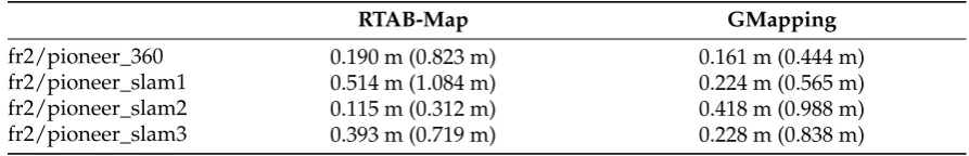
Table6shows the SLAM accuracy of the selected algorithms for the TUM RGB-D datasets. 356
Table 6.Absolute Trajectory Error (ATE) of the SLAM algorithms on TUM RGB-D datasets (maximum error is shown enclosed in parentheses).
RTAB-Map GMapping
fr2/pioneer_360 0.190 m (0.823 m) 0.161 m (0.444 m)
fr2/pioneer_slam1 0.514 m (1.084 m) 0.224 m (0.565 m) fr2/pioneer_slam2 0.115 m (0.312 m) 0.418 m (0.988 m) fr2/pioneer_slam3 0.393 m (0.719 m) 0.228 m (0.838 m)
The results show that GMapping has a marginally lower RMSE ATE for the datasets 357
fr2/pioneer_360and fr2/pioneer_slam3 than RTAB-Map. It has a significantly lower RMSE for the 358
datasetfr2/pioneer_slam1. These results clearly show the advantage of lidar based SLAM, since in 359
the selected TUM datasets of these experiments GMapping uses a SICK laser as its sensor instead of 360
the emulated scan from RGB-D data. However, RTAB-Map has lower error than GMapping for the 361
datasetfr2/pioneer_slam2. This can be explained by the fact that in most part of the mapping session, 362
RTAB-Map is not able to compute visual odometry estimates. This in turn biases the ATE metric since 363
the error is being computed for an incomplete trajectory. In the other hand, the same result shows that 364
RTAB-Map is able to recover its pose (compute a valid robot pose after being considered lost). 365
5.3. Mapping Quality: Simulation Datasets 366
Occupancy grid maps produced by GMapping and RTAB-Map after processing the simulated 367
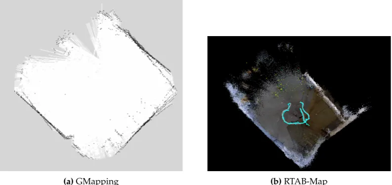
datasets can be viewed in Figure4(sim_short) sequence and Figure5(sim_large) sequence. 368
(a)GMapping (b)RTAB-Map
(a)GMapping (b)RTAB-Map
Figure 5.Results on thesim_longsimulation dataset.
Comparing the computed grids with the top view of the mapped environment (Figure1), it can be 369
seen that GMapping reconstructs a correct representation of the environment, while the grid produced 370
by RTAB-Map has visible misalignments. 371
Because RTAB-Map does not use odometry, the computed grid by this algorithm shows more 372
proeminent misalignments than those present in the results of GMapping, which is using error free 373
odometry estimates. 374
The unmapped portion of the grids (center of the map) are present because the robot trajectory 375
did not performed sensor measurements in these areas. 376
5.4. Mapping Quality: TUM Datasets 377
The occupancy grid maps computed by GMapping for each dataset of the TUM set are shown 378
on Figure9. Occupancy grid maps cannot be computed by RTAB-Map for the TUM datasets because 379
these experiments were run on the standalone version of RTAB-Map (as explained in Section4.1.2). 380
Instead, as the result of RTAB-Map we compute top view projections of the point clouds. 381
(a)GMapping (b)RTAB-Map
(a)GMapping (b)RTAB-Map
Figure 7.Results on the TUMfr2/pioneer_slam1dataset.
(a)GMapping (b)RTAB-Map
Figure 8.Results on the TUMfr2/pioneer_slam2dataset.
(a)GMapping (b)RTAB-Map
Figure 9.Results on the TUMfr2/pioneer_slam3dataset.
GMapping computes occupancy grid in the form of a large squared area predominantly composed 382
these images. Note however that the maps were computed processing laser data instead of the RGB-D 384
data from Kinect. Nevertheless, duplicated walls (i.e. accumulated error) can be seen in the maps of 385
fr2/pioneer_slam2andfr2/pioneer_slam3datasets. 386
RTAB-Map computes 3D point clouds coherent with the mapped environment albeit some maps 387
are clearly incomplete. During the mapping process, RTAB-Map estimates incorrect robot poses 388
that are later corrected (fr2/pioneer_360efr2/pioneer_slam). It is able to detect a large loop closure 389
(fr2/pioneer_slam2) as well. As already discussed on Section5.2, the robot does not compute odometry 390
estimates for a long period of time because it visits an area without any visual features within the 391
range of the camera. Duplicated walls are present on the maps offr2/pioneer_slam1and non orthogonal 392
walls on the maps offr2/pioneer_360andfr2/pioneer_slam2. 393
5.5. Mapping Quality: Datasets Collected at UFRN 394
The computed occupancy grids by GMapping and RTAB-Map for the data collected at our 395
university are shown on Figure10(DCA_corridordataset). 396
(a)GMapping
(b)RTAB-Map
(a)GMapping
(b)RTAB-Map
Figure 11.Results on theDCA_completedataset.
When mapping the datasetDCA_corridor, GMapping estimates the main corridor in a non 397
perpendicular way in relation to the laboratory from which the robot starts the mapping session. The 398
walls of the corridor are coherent with the true structure of the environment. Importantly, moving 399
persons appearing in the images are not added to the grid map. This is correct, since the grid should 400
capture the static structure of the environment. The robot arrives back in the laboratory, resulting in 401
duplicated estimates of the room. 402
For the larger dataset DCA_complete, the same non perpendicular alignment between the 403
laboratory and the corridor is estimated. During the session, the robot enters an area of the department 404
in which there is a fork joining two secondary corridors (left corridor and right corridor). It then 405
proceeds with the mapping through the left corridor, completes a loop around the building and arrives 406
in the same location of the fork. However, this time the robot enters the area with the fork arriving from 407
the right corridor, when it is clearly seen that it has accumulated large mapping errors (a duplicate of 408
the main corridor and laboratory is estimated on the map). 409
If used with the configuration stated in Section3.2.1, RTAB-Map computes SLAM estimates of 410
very bad quality. This happens because of the low availability of visual features on the mapped area, 411
which are not sufficient for visual odometry and consequently for the pose optimized pose graph. For 412
this reason, we configured RTAB-Map to estimate odometry using both robot odometry and emulated 413
laser scan from the RGB-D camera. 414
RTAB-Map computes an estimate of the map onDCA_corridorthat is coherent with the mapped 415
structure, despite some duplicated walls along the main corridor. Even with these errors, the main 416
portion of the corridor is accurately mapped, which is relevant for route planning and navigation in 417
general. Unlike GMapping, the perpendicular relation between the laboratory and the corridor is 418
represented on the grid. Between 3:11s and 3:15s of the video sequence, we can see that loop closures 419
are correctly detected by the algorithm, which in turn triggers a map optimization. 420
The complete area of the mapped building is correctly reconstructed by RTAB-Map after 421
processing the datasetDCA_complete. However, this result is only available at the end of the dataset, 422
with those in the visual memory captured at the beginning. This loop closure detection triggers 424
an optimization that corrects the accumulated error by the algorithm. Before arriving back at the 425
laboratory, the error can be seen by incorrect duplicates of the main corridor, although with a lesser 426
magnitude than those of GMapping. 427
5.6. Reuse of Maps by the Algorithms 428
Our evaluation of GMapping of RTAB-Map also involves the reuse of grid maps produced by 429
these algorithms, as explained in Section4.4. To evaluate this capability, we reused the grid map 430
computed with the best quality (Figure11.b). GMapping does not have a localization only mode as 431
does RTAB-Map. 432
Hence, we loaded the map on RTAB-Map and then, supply an approximate estimate of the initial 433
robot pose within the grid map using RVIZ, a ROS tool that offers the possibility to insert the pose via 434
a drag and drop interface. 435
We then navigate the robot through waypoint locations within the map, for which we use RVIZ 436
to indicate goal locations for robot navigation. A total of five waypoints is given to the robot. The ROS 437
navigation system is not able to compute a valid path for the first waypoint, since it was indicated 438
on a small area with various scattered (and dynamic) objects. For the rest of the waypoints, the robot 439
performed navigation without problems, avoiding moving persons that passed in front of it. 440
Although GMapping does not offer localization only mode, the ROS package for Adaptive Monte 441
Carlo Localization (AMCL) [57], which works similarly in principle to GMapping, can also be used for 442
this task. We performed the same experiment with a prebuilt map for navigation and confirmed the 443
applicability of AMCL. 444
5.7. Discussion 445
When autonomously mapping an environment, it is interesting for the robots to have a number 446
of capabilities. We draw the following considerations based on the results of our experiments and 447
used setup (indoor planar robot with a RGB-D camera). The discussion further assumes that a decent 448
processing power is available for both algorithms. 449
Regarding SLAM, the algorithms should compute correct pose estimates, detect previously visited 450
places and minimize accumulated error. 451
The results of our experiments show that both GMapping and RTAB-Map have low error estimates, 452
as evidenced by the RMSE ATE metric. However, GMapping meets these requirements only partially, 453
since it is not able minimize the accumulated error if it grows substantially (as happens in the 454
experiments with our datasets). RTAB-Map recovers robot pose when revisiting places even in 455
cases where visual odometry is not computed for a long period of time. 456
In relation to the maps produced by SLAM algorithms, the results of experiments and our previous 457
experiences [46] emphasize that the maps computed by SLAM can be useful for robot navigation if 458
this subsystem offers them in the form of a occupancy grid map, as is the case of GMapping and 459
RTAB-Map. The estimated grids must capture the static structure of the mapped environment, since 460
dynamic objects can be avoided by the reactive behavior of path planning algorithms. In this aspect, 461
RTAB-Map performs better than GMapping in scenarios where the robot is equipped with a low cost 462
RGB-D camera as is the case of our experiments. 463
It is important to note that these findings are not obvious from simulation experiments, since the 464
simulated data are not corrupted with actual noise as those found in the experiments with real robots. 465
6. Conclusion 466
This work proposed an experimental analysis of two widely used ROS compatible SLAM 467
packages: GMapping and RTAB-Map. The experiments were carried out by executing SLAM and 468
navigation sessions on datasets from Gazebo simulation, TUM RGB-D benchmarks [21] and using 469
with the inner workings and main parameters of the respective ROS implementation. Specifically, we 471
found that RTAB-Map is a more complete solution for ground robots equipped with a RGB-D sensor, 472
mainly because of capabilities like accuracy, quality of produced maps and configuration flexibility, 473
which allows it to reuse maps in localization only mode. 474
Besides the detailed analysis performed, our dataset is also another contribution to the community 475
that can use it in further works. This dataset will be made available as soon as another report will be 476
written or it can be asked by requesting to us. So we believe that the analysis reported on this work 477
should shed light for researchers involved with ROS application design in choosing a SLAM package 478
that computes estimates suitable for ground robots equipped with a RGB-D sensor to autonomously 479
navigate an environment. 480
Author Contributions:Conceptualization, B.S. and R.X.; methodology, B.S.; software, R.X.; investigation, B.S. 481
and R.X.; resources, B.S. and L.G.; data curation, R.X.; writing—original draft preparation, B.S. and R.X.; 482
writing—review and editing, B.S. and L.G.; supervision, B.S. and L.G.; project administration, B.S. and L.G.; 483
funding acquisition, B.S. and L.G. 484
Funding:We thank to Brazilian sponsoring agencies for research CNPq and Capes (under grant number 001) for 485
the financial support. 486
Conflicts of Interest:The authors declare no conflict of interest. 487
References 488
1. Thrun, S.; Burgard, W.; Fox, D.Probabilistic Robotics (Intelligent Robotics and Autonomous Agents); The MIT 489
Press, 2005. 490
2. Durrant-Whyte, H.; Bailey, T. Simultaneous localization and mapping: part I.IEEE Robotics and Automation
491
Magazine2006,13, 99–110. doi:10.1109/MRA.2006.1638022. 492
3. Bailey, T.; Durrant-Whyte, H. Simultaneous localization and mapping (SLAM): part II.IEEE Robotics and
493
Automation Magazine2006,13, 108–117. doi:10.1109/MRA.2006.1678144. 494
4. Siciliano, B.; Khatib, O.Springer Handbook of Robotics; Springer-Verlag: Berlin, Heidelberg, 2007. 495
5. Vincent, R.; Limketkai, B.; Eriksen, M. Comparison of indoor robot localization techniques in the 496
absence of GPS. Proceedings of SPIE - The International Society for Optical Engineering2010, pp. 1–8. 497
doi:10.1117/12.849593. 498
6. Carlone, L.; Aragues, R.; Castellanos, J.; Bona, B. A Linear Approximation for Graph-based Simultaneous 499
Localization and Mapping. Robotics: Science and Systems (RSS), 2012. doi:10.15607/RSS.2011.VII.006. 500
7. Endres, F.; Hess, J.; Sturm, J.; Cremers, D.; Burgard, W. 3-D Mapping With an RGB-D Camera. IEEE
501
Transactions on Robotics2014,30, 177–187. doi:10.1109/TRO.2013.2279412. 502
8. Hess, W.; Kohler, D.; Rapp, H.; Andor, D. Real-time loop closure in 2D LIDAR SLAM. 503
2016 IEEE International Conference on Robotics and Automation (ICRA), 2016, pp. 1271–1278. 504
doi:10.1109/ICRA.2016.7487258. 505
9. Labbé, M.; Michaud, F. RTAB-Map as an open-source lidar and visual simultaneous localization and 506
mapping library for large-scale and long-term online operation. Journal of Field Robotics2019,36, 416–446. 507
doi:10.1002/rob.21831. 508
10. Quigley, M.; Conley, K.; Gerkey, B.; Faust, J.; Foote, T.; Leibs, J.; Wheeler, R.; Ng, A.Y. ROS: an open-source 509
Robot Operating System. ICRA Workshop on Open Source Software, 2009, p. 5. 510
11. Brian Gerkey. ROS, the Robot Operating System, Is Growing Faster Than Ever, Celebrates 8 511
Years. https://spectrum.ieee.org/automaton/robotics/robotics-software/ros-robot-operating-system-512
celebrates-8-years, 2015. 513
12. Grisetti, G.; Stachniss, C.; Burgard, W. Improved Techniques for Grid Mapping With Rao-Blackwellized 514
Particle Filters.IEEE Transactions on Robotics2007,23, 34–46. doi:10.1109/TRO.2006.889486. 515
13. Steux, B.; Hamzaoui, O.E. tinySLAM: A SLAM algorithm in less than 200 lines C-language program. 516
Proceedings IEEE International Conference on Control Automation Robotics and Vision,pages (ICARCV). 517
14. Kohlbrecher, S.; von Stryk, O.; Meyer, J.; Klingauf, U. A flexible and scalable SLAM system with full 3D 519
motion estimation. 2011 IEEE International Symposium on Safety, Security, and Rescue Robotics, 2011, pp. 520
155–160. doi:10.1109/SSRR.2011.6106777. 521
15. Engel, J.; Schöps, T.; Cremers, D. LSD-SLAM: Large-Scale Direct Monocular SLAM. Computer Vision – 522
ECCV 2014; Fleet, D.; Pajdla, T.; Schiele, B.; Tuytelaars, T., Eds.; Springer International Publishing: Cham, 523
2014; pp. 834–849. 524
16. Mur-Artal, R.; Montiel, J.M.M.; Tardós, J.D. ORB-SLAM: a Versatile and Accurate Monocular SLAM 525
System. IEEE Transactions on Robotics2015,31, 1147–1163. doi:10.1109/TRO.2015.2463671. 526
17. Mur-Artal, R.; Tardós, J.D. ORB-SLAM2: An Open-Source SLAM System for Monocular, Stereo, and 527
RGB-D Cameras. IEEE Transactions on Robotics2017,33, 1255–1262. doi:10.1109/TRO.2017.2705103. 528
18. Marder-Eppstein, E.; Berger, E.; Foote, T.; Gerkey, B.; Konolige, K. The Office Marathon: Robust navigation 529
in an indoor office environment. 2010 IEEE International Conference on Robotics and Automation (ICRA), 530
2010, pp. 300–307. doi:10.1109/ROBOT.2010.5509725. 531
19. Ortiz, L.; Cabrera, V.; Goncalves, L. Depth Data Error Modeling of the ZED 3D Vision Sensor from 532
Stereolabs. ELCVIA Electronic Letters on Computer Vision and Image Analysis2018,17, 1–15. 533
20. Cabrera, E.V.; Ortiz, L.E.; Silva, B.M.F.d.; Clua, E.W.G.; Gonçalves, L.M.G. A Versatile Method for Depth 534
Data Error Estimation in RGB-D Sensors. Sensors2018,18. doi:10.3390/s18093122. 535
21. Sturm, J.; Engelhard, N.; Endres, F.; Burgard, W.; Cremers, D. A benchmark for the evaluation of RGB-D 536
SLAM systems. 2012 IEEE/RSJ International Conference on Intelligent Robots and Systems, 2012, pp. 537
573–580. doi:10.1109/IROS.2012.6385773. 538
22. Arumugam, R.; Enti, V.R.; Bingbing, L.; Xiaojun, W.; Baskaran, K.; Kong, F.F.; Kumar, A.S.; Meng, K.D.; Kit, 539
G.W. DAvinCi: A cloud computing framework for service robots. 2010 IEEE International Conference on 540
Robotics and Automation, 2010, pp. 3084–3089. doi:10.1109/ROBOT.2010.5509469. 541
23. Koubaa, A. ROS As a Service: Web Services for Robot Operating System. Journal of Software Engineering for
542
Robotics2015,1, 1. 543
24. Costa, L.F.; Gonçalves, L.M.G. RoboServ: A ROS Based Approach towards Providing Heterogeneous 544
Robots as a Service. 2016 XIII Latin American Robotics Symposium and IV Brazilian Robotics Symposium 545
(LARS/SBR), 2016, pp. 169–174. doi:10.1109/LARS-SBR.2016.35. 546
25. Crick, C.; Jay, G.; Osentoski, S.; Pitzer, B.; Jenkins, O.C. Rosbridge: ROS for Non-ROS Users. International 547
Symposium on Robotics Research (ISRR), 2011. 548
26. Alisher, K.; Alexander, K.; Alexandr, B. Control of the Mobile Robots with ROS in Robotics Courses. 549
Procedia Engineering2015,100, 1475 – 1484. doi:http://dx.doi.org/10.1016/j.proeng.2015.01.519. 550
27. Rezeck, P.A.F.; Vieira, M.A.M.; Chaimowicz, L.; Campos, M.F.M. On the Development of a Robotic 551
System for Telepresence. 2013 Latin American Robotics Symposium and Competition, 2013, pp. 8–13. 552
doi:10.1109/LARS.2013.49. 553
28. Costa, L.F.S.; Nascimento, T.P.; Maia, R.d.S.; Gonçalves, L.M.G. N-learning: An Approach for Learning and 554
Teaching Skills in Multirobot Teams.Robotica2019, p. 1–21. doi:10.1017/S0263574719000468. 555
29. Grisetti, G.; Kummerle, R.; Stachniss, C.; Burgard, W. A Tutorial on Graph-Based SLAM.IEEE Intelligent
556
Transportation Systems Magazine2010,2, 31–43. doi:10.1109/MITS.2010.939925. 557
30. Montemerlo, M.; Thrun, S.; Koller, D.; Wegbreit, B. FastSLAM: A Factored Solution to the Simultaneous 558
Localization and Mapping Problem. Eighteenth National Conference on Artificial Intelligence; American 559
Association for Artificial Intelligence: Menlo Park, CA, USA, 2002; pp. 593–598. 560
31. Davison, A.J. Real-Time Simultaneous Localisation and Mapping with a Single Camera. IEEE International 561
Conference on Computer Vision (ICCV). IEEE, 2003, p. 1403. 562
32. Klein, G.; Murray, D. Parallel Tracking and Mapping for Small AR Workspaces. IEEE 563
International Symposium on Mixed and Augmented Reality (ISMAR). IEEE, 2007, pp. 1–10. 564
doi:http://dx.doi.org/10.1109/ISMAR.2007.4538852. 565
33. Se, S.; Lowe, D.; Little, J. Mobile Robot Localization and Mapping with Uncertainty using 566
Scale-Invariant Visual Landmarks. The International Journal of Robotics Research 2002, 21, 735–758, 567
[https://doi.org/10.1177/027836402761412467]. doi:10.1177/027836402761412467. 568
34. Geiger, A.; Ziegler, J.; Stiller, C. StereoScan: Dense 3d reconstruction in real-time. 2011 IEEE Intelligent 569
35. Endres, F.; Hess, J.; Engelhard, N.; Sturm, J.; Cremers, D.; Burgard, W. An Evaluation of the RGB-D SLAM 571
System. IEEE International Conference on Robotics and Automation (ICRA). IEEE, 2012, pp. 1691–1696. 572
36. Cadena, C.; Carlone, L.; Carrillo, H.; Latif, Y.; Scaramuzza, D.; Neira, J.; Reid, I.; Leonard, J.J. Past, 573
Present, and Future of Simultaneous Localization and Mapping: Toward the Robust-Perception Age. IEEE
574
Transactions on Robotics2016,32, 1309–1332. doi:10.1109/TRO.2016.2624754. 575
37. Scaramuzza, D.; Fraundorfer, F. Visual Odometry [Tutorial]. IEEE Robotics Automation Magazine2011, 576
18, 80–92. doi:10.1109/MRA.2011.943233. 577
38. Hartley, R.; Zisserman, A.Multiple View Geometry in Computer Vision, 2 ed.; Cambridge University Press: 578
New York, NY, USA, 2003. 579
39. Lowe, D.G. Distinctive Image Features from Scale-Invariant Keypoints. International Journal of Computer
580
Vision2004,60, 91–110. doi:http://dx.doi.org/10.1023/B:VISI.0000029664.99615.94. 581
40. Bay, H.; Ess, A.; Tuytelaars, T.; Gool, L.V. Speeded-Up Robust Features (SURF).Computer Vision and Image
582
Understanding2008,110, 346–359. doi:http://dx.doi.org/10.1016/j.cviu.2007.09.014. 583
41. Rublee, E.; Rabaud, V.; Konolige, K.; Bradski, G. ORB: An efficient alternative to SIFT or 584
SURF. IEEE International Conference on Computer Vision (ICCV). IEEE, 2011, pp. 2564–2571. 585
doi:10.1109/ICCV.2011.6126544. 586
42. Forster, C.; Pizzoli, M.; Scaramuzza, D. SVO: Fast semi-direct monocular visual odometry. 587
2014 IEEE International Conference on Robotics and Automation (ICRA), 2014, pp. 15–22. 588
doi:10.1109/ICRA.2014.6906584. 589
43. Gálvez-López, D.; Tardós, J.D. Bags of Binary Words for Fast Place Recognition in Image Sequences.IEEE
590
Transactions on Robotics2012,28, 1188–1197. doi:10.1109/TRO.2012.2197158. 591
44. Huang, A.S.; Bachrach, A.; Henry, P.; Krainin, M.; Fox, D.; Roy, N. Visual odometry and mapping for 592
autonomous flight using an RGB-D camera. In Proc. of the Intl. Sym. of Robot. Research (ISRR), 2011. 593
45. Dryanovski, I.; Valenti, R.G.; Xiao, J. Fast visual odometry and mapping from RGB-D 594
data. 2013 IEEE International Conference on Robotics and Automation, 2013, pp. 2305–2310. 595
doi:10.1109/ICRA.2013.6630889. 596
46. Silva, B.M.F.; Xavier, R.S.; do Nascimento, T.P.; Gonçalves, L.M.G. Experimental evaluation of ROS 597
compatible SLAM algorithms for RGB-D sensors. 2017 Latin American Robotics Symposium (LARS) and 598
2017 Brazilian Symposium on Robotics (SBR), 2017, pp. 1–6. doi:10.1109/SBR-LARS-R.2017.8215331. 599
47. Santos, J.M.; Portugal, D.; Rocha, R.P. An evaluation of 2D SLAM techniques available in Robot Operating 600
System. 2013 IEEE International Symposium on Safety, Security, and Rescue Robotics (SSRR), 2013, pp. 601
1–6. doi:10.1109/SSRR.2013.6719348. 602
48. Alexander Buyval, Ilya Afanasyev, E.M. Comparative analysis of ROS-based monocular SLAM methods 603
for indoor navigation. 2016 International Conference on Machine Vision (ICMV), 2016, Vol. 10341. 604
doi:10.1117/12.2268809. 605
49. Ibragimov, I.Z.; Afanasyev, I.M. Comparison of ROS-based visual SLAM methods in homogeneous indoor 606
environment. 2017 14th Workshop on Positioning, Navigation and Communications (WPNC), 2017, pp. 607
1–6. doi:10.1109/WPNC.2017.8250081. 608
50. Koenig, N.; Howard, A. Design and use paradigms for Gazebo, an open-source multi-robot simulator. 2004 609
IEEE/RSJ International Conference on Intelligent Robots and Systems (IROS) (IEEE Cat. No.04CH37566), 610
2004, Vol. 3, pp. 2149–2154 vol.3. doi:10.1109/IROS.2004.1389727. 611
51. Quigley, M.; Gerkey, B.; Smart, W.D. Programming Robots with ROS: A Practical Introduction to the Robot
612
Operating System, 1st ed.; O’Reilly Media, Inc., 2015. 613
52. Labbé, M.; Michaud, F. Appearance-Based Loop Closure Detection for Online Large-Scale and Long-Term 614
Operation. IEEE Transactions on Robotics2013,29, 734–745. doi:10.1109/TRO.2013.2242375. 615
53. Shi, J.; Tomasi, C. Good Features to Track. IEEE Conference on Computer Vision and Pattern Recognition 616
(CVPR). IEEE, 1994, pp. 593–600. 617
54. Calonder, M.; Lepetit, V.; Strecha, C.; Fua, P. BRIEF: Binary Robust Independent Elementary Features. 618
Computer Vision – ECCV 2010; Daniilidis, K.; Maragos, P.; Paragios, N., Eds.; Springer Berlin Heidelberg: 619
Berlin, Heidelberg, 2010; pp. 778–792. 620
55. Segal, A.; Hähnel, D.; Thrun, S. Generalized-ICP. Robotics: Science and Systems (RSS), 2009. 621
56. Rasouli, A.; Tsotsos, J.K. The Effect of Color Space Selection on Detectability and Discriminability of 623
Colored Objects. CoRR2017,abs/1702.05421,[1702.05421]. 624
57. Fox, D.; Burgard, W.; Dellaert, F.; Thrun, S. Monte Carlo Localization: Efficient Position Estimation 625
for Mobile Robots. Proceedings of the Sixteenth National Conference on Artificial Intelligence and the 626
Eleventh Innovative Applications of Artificial Intelligence Conference Innovative Applications of Artificial 627
Intelligence; American Association for Artificial Intelligence: Menlo Park, CA, USA, 1999; AAAI ’99/IAAI 628
’99, pp. 343–349. 629
630