Article
1
Motion Intention Estimation for Active Power-Assist
2
Lower Limb Exoskeleton Robot (APAL)
3
Mantian Li 1, 2, Jing Deng 1, Fusheng Zha 1, 2,*, Shiyin Qiu 1, and Xin Wang 2
4
1 State Key Laboratory of Robotics and System, Harbin Institute of Technology (HIT), Harbin 150001, China;
5
Emails: [email protected] (M.L.); [email protected] (J.D.); [email protected] (F.Z.); [email protected] (S.Q.).
6
2 Shenzhen Academy of Aerospace Technology, Shenzhen 518000, China; Email: [email protected]
7
(X.W.).
8
* Corresponding author: [email protected]; Tel.: +86-0451-86414174
9
10
11
Abstract: The active power-assist function greatly expands the potential applications of exoskeleton
12
robots, yet the motion intention estimation (MIE) for active power-assist strategy is quite problematic.
13
Through the analysis of the conduction path and the different stage manifestations of motion
14
intention in human body, we confirmed that the joint torque of human body meets the basic
15
requirements of MIE for the active power-assist that we suggest, namely: (i) it reflects the direction
16
and intensity of the wearer’s efforts; (ii) it precedes the human limb motion; (iii) it generates real-time
17
and continuous output. Thus, an online calculation method of human joint torque was proposed. The
18
sensing system integrated in exoskeleton robots was designed to perceive motion data and foot
19
contact force of a human body. A special inverse dynamics with a parameterized model of the human
20
body was proposed. Contrast experiments were carried out with the motion capture system, which
21
results’ accuracy and similarity were evaluated via the root mean square error and correlation
22
coefficient. The comparative analysis of two synchronous results shows good accuracy of the
23
proposed MIE method, which lays the foundation for the realization of active power-assist.
24
Keywords: motion intention estimation; active power-assist; exoskeleton robot; inverse dynamics.
25
26
1. Introduction
27
The active power-assist function can greatly expands the potential applications of exoskeleton
28
robots by expanding physical capability of human body, such as enabling amyotrophic patients to
29
regain walking ability, helping the elderly to climb stairs, and enhancing soldiers to exceed their
30
physical limits, i.e., run faster and jump higher. The motion of a human body is complicated and has
31
strong randomness, and the recognition of the human motion intentions is always confusing. To
32
realize active power-assist, the exoskeleton needs to prejudge the wearer’s intention and actively
33
assist the limb motion of the human body, which poses new challenges to the motion intention
34
estimation (MIE) technology.
35
MIE can be seen as a particular way for the robot to obtain the operators’ instructions. The
36
conventional machine reads the operator's instructions through a human-machine interface such as
37
a keyboard or buttons. Assistive exoskeleton for paraplegic patients such as ReWalk [1], EKSO [2],
38
i.e. also use buttons on the cane to input some simple and discrete upper-level instructions, such as
39
stand up, sit down, walk along, etc., while the lower-level instructions such as joints’ movement are
40
taken over by the exoskeleton. This kind of simple approach is accessible for handicapped person,
41
but it limits the wearer’s flexibility and is hard to adapt to the complex environment.
42
Supporting arbitrary motion of the wear is our first concern on MIE method. Coordination with
43
wearer’s joints movement instead of replacing them is more likely for an exoskeleton robot to support
44
random movement of the wearer. The technology of directly manipulating a robot through the
45
human limb movement has been elaborated and brought significant benefits to the teleoperation and
46
minimally invasive surgery [3]. There are several ways to extract motion intentions. The sensitivity
47
amplification control (SAC) method [4] proposed at the UC Berkeley and implemented in BLEEX
48
exoskeleton is widely studied. The dynamic feedforward compensation [5] makes the BLEEX
49
transparent to external force, which, thus, spontaneously follows the human body. The
human-50
machine movement deviation (HMMD)-based MIE is used in the upper limb ULERD [6] and
load-51
carrying PRMI [7] exoskeletons. The attitude deviations are detected and transferred into joints
52
velocity or torque command for the exoskeleton to catch up. The human-machine contact force
53
(HMCF)-based MIE seems better [8, 9], because it is less likely to cause asynchronies and motion
54
interference. Man-machine interaction force indicates the direction and speed of the human body,
55
which reduces the task for the exoskeleton to tracking of the human body with impedance control or
56
other strategies. The above SAC, HMMD, and HMCF are MIE methods for follow-up strategies
57
whose significant drawback is that the exoskeleton will not actively overtake the wearer’s efforts to
58
drag his/her limbs towards the desired direction.
59
Actively assisting the human body is our second concern on MIE. The exoskeleton robot should
60
not just follow, but estimate the wearer's needs and take the initiative to assist. The Hybrid Assistive
61
Limb (HAL) built by Cyberdyne Inc., Tsukuba, Japan, is a typical active power-assist type [10]. They
62
use muscle activity to represent the wearer’s motion intention, and major breakthrough was made.
63
The muscle activity was estimated from electromyography (EMG) signals and convert into the
64
wearer’s joints torque, then the HAL generate power assist torque by amplifying the wearer’s own
65
joint torque. Many other exoskeletons with EMG method also confirm that the muscle activity based
66
MIE is suitable for realizing active power-assist function [11-13]. There are also other methods for
67
estimating the muscle activity, e.g., the muscle stiffness method [14]. However, it is not easy to
68
calculate joint torque from EMG signals, because there are many imprecise physical models between
69
the EMG signals and the joint torques, such as the muscle force versus EMG signal, moment arm of
70
the muscle versus angle of the joint, and the redundancy induced by the multiple muscles driving
71
the same joint, etc. [15]. All this results in increasing complexity and uncertainty in actual
72
implementation.
73
The above brief survey of MIEs for different type of exoskeletons indicates that human motion
74
intention can be tracked in multiple different ways. The original keyboard-and-buttons-based MIE
75
limit user’s flexibility. The SAC, HMMD and HMCF methods extract human intention form the
76
wearer’s limb motion, man-machine attitude deviations and interaction force, which can support
77
arbitrary motion of human body, but are limited to follow-up strategy. The active power-assist
78
function was successfully realized with the muscle-activity-based MIE, yet the complexity and
79
uncertainty limit its application.
80
This paper discusses the MIE method for the active power-assist lower limb (APAL) exoskeleton
81
robot. We first analyzed the manifestations of human motion intention in different stage, then,
82
critically choose the joint torque to be the motion intention, and briefly explained its effectiveness for
83
the active power-assist function. The rest main problem is the accurate estimation of the wearer’s
84
joint torque. A parameterized model of the human body is established and inverse dynamics
85
specially solved. A sensor system integrated in the exoskeleton structure is designed to detect
86
movement and posture of the human body, and a pair of special shoes are developed to measure the
87
wearer’s foot contact force. With all these sensor signals, joint torque of the human lower limbs was
88
calculated on line. Contrast experiments were carried out with a motion capture system to evaluate
89
the accuracy of the newly proposed sensor system and algorithm.
90
2. Materials and Methods
91
2.1. Definition of motion intention
92
The motion intentions arising from the brain are converted into nerve impulses by the central
93
nervous system and control the coordinate motion of muscle groups. The nerve impulses transfer
94
along the nerve fibers to the muscle cells, causing the muscle contraction, thereby pulling the adjacent
95
bones to generate joint torques, and driving the limbs to form the body movement. Finally, the limbs
96
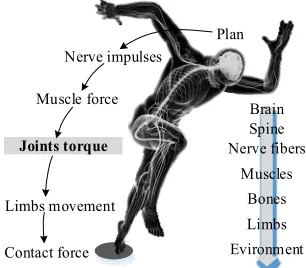
interact with environment to generate contact forces [16], as shown in Figure 1. It can be seen that the
motion intention has different forms at different stages from its generation to the manifestation. The
98
motion intention can be represented from different aspects by EEG, nerve impulse, EMG, muscle
99
force, joint torque, limb motion, limb posture, and contact forces. However, not any of these signals
100
that can be extracted satisfies the conditions, which are required for the accurate interpretation of the
101
motion intention and further realization of the active power-assist strategy. The appropriate MIE
102
should have the following features:
103
1) Reflects the direction and intensity of the wearer’s efforts;
104
2) Precedes the human limb motion;
105
3) Generates real-time and continuous output.
106
Correct direction helps prevent counteraction, while liner response to the effort intensity is
107
essential for soft contact and cooperative movement. Precede the human limb motions to actively
108
pull the human body to achieve the power-assist. Real-time and continuity features enable the
109
controller to generate real-time instructions.
110
The intention for active power-assist is no longer an upper-level command, such as stand up or
111
sit down, but a series of real-time and specific control instructions to each dynamic joints. Similarly,
112
a cab passenger intention to travel from the foot of the mountain to the top implies no straightforward
113
realization of the “drive up the hill” macro-command. Instead, the cab driver (or self-driving car
114
system) must control the car direction, throttle and brake on each ramp, and make all the required
115
turns.
116
Plan
Brain Spine Nerve fibers
Muscles
Limbs Nerve impulses
Muscle force
Bones Joints torque
Limbs movement
Evironment Contact force
117
Figure 1. The transfer link and manifestation of motion intention
118
In the entire conduction chain of the motion intention, the limb movement and contact force are
119
more accessible but less informative than the joints’ torque. For example, when a person under study
120
generates a muscle torque to stretch the knee joint, the knee will extend with acceleration, or contract
121
with deceleration, or just stay still to maintain a half squat posture. From the detected movement of
122
the knee joint, the observer cannot judge the direction of the person’s motion intention, in contrast to
123
the joint torque, which exactly fits the above four requirements. Firstly, the sign of the joint torque
124
represents the effort’s direction. Secondly, the magnitude of the joint torque linearly reflects the effort
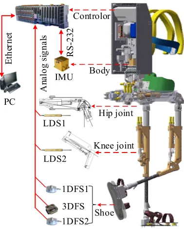
125
intensity. Thirdly, it is well-known that force causes the acceleration of an object, and its trajectory is
126
obtained by the double integration of the acceleration, so the joint torque is always ahead of the limb
127
trajectory. Finally, the joint torque continuously reflects the wearer’s motion intention in the real time
128
scale. Medical data show that the nerve impulse from the central nervous system reaches the muscle
129
contraction in about 10ms [17]. Meanwhile, the bandwidth of the human lower limb is less than 5Hz
130
[18], which implies the system delay of 250ms. It is 25 times higher than that of the nerve impulse
131
reaching the joint torque. Therefore, the latter delay is negligible, while the joint torque is chosen to
132
represent the wearer’s motion intention, insofar as it meets the above requirements of active
power-133
assist.
134
2.2. The active power-assist mechanism
135
Assuming that the exoskeleton robot acquires the data on its wearer’s joint torque in real-time,
136
and exerts a fully equivalent torque on the human body, the wearer will need little effort to move
his/her limbs. This is the origin of the proposed active power-assist method. It provides the muscular
138
torque proportional compensation (MTPC), which allows the human body to maintain its posture
139
and state of motion through the exoskeleton robot. This method (hereinafter referred to as MTPC
140
method) has the following mathematical description:
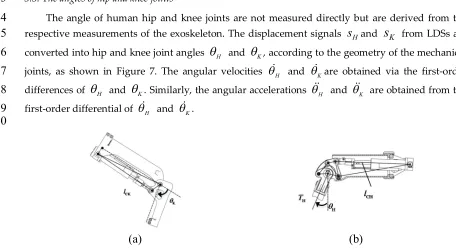
141
=
=
0
1
H E
E
,(
)
(1)where
is the required torque for the human body,
H is the muscular torque generated by142
human muscles,
E is the auxiliary torque from the exoskeleton, and
is the assistive factor.143
Noteworthy is that no exoskeleton is expected to completely replace muscles of the human body,
144
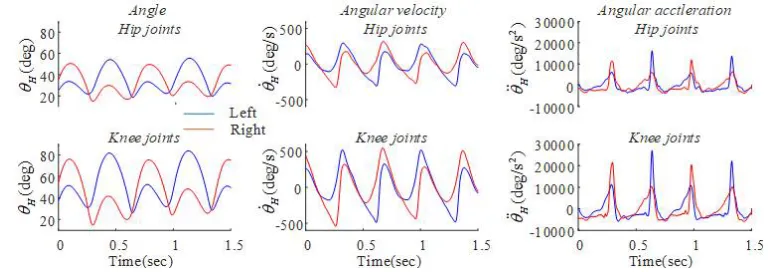
because human skin cannot bear excessive loads. Therefore, the assistive factor is selected in the range
145
from 0 to 0.25 [19]. Here, we briefly attest the active power-assist strategy in the aspect of the
146
reduction of power and torque amplitude.
147
Assume that P is the total power required by the joint for completing a particular action. When
148
the exoskeleton assists the human body to perform the same action, the total power should remain
149
unchanged. This yields
150
=
H E=
H EP
P
P
(2)where
P
H is human muscle power,P
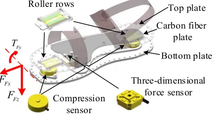
E is the exoskeleton power, and
is joint angular velocity.151
Substitution of Equation 2 into Equation 1 yields
152
|
|=|1- | | |
| |
|
|=|1- | | |
| |
H
H
P
P
P
(3)It can be seen that the MTPC method can reduce both the amplitude of the joint torque and the
153
power consumption of the human body, which theoretically realizes the active power-assist
154
functionality. Moreover, there is no need for this method to distinguish the forms of motion, such as
155
forward or backward ones, accelerating or decelerating, walking, running, jumping, or other. This is
156
a general method, which seems to very lucrative for the support of arbitrary movements of the human
157
body.
158
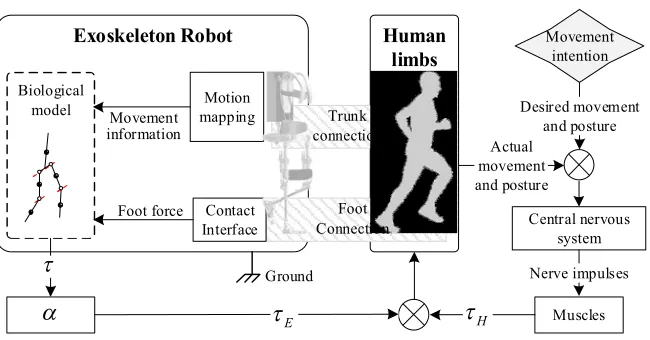
The architecture of active power-assist loop is shown in Figure 2. In such a human-machine
159
coupled system, there are two controllers, one is the human brain, and the other is the CPU of the
160
exoskeleton robot. The role of the human brain is to sense the actual movement of the body through
161
the cochlea/inner ear, vision, touch, and so on, and to emit the nerve impulses to drive the body
162
toward the desired state; the role of the exoskeleton robot is to assist the human body. Therefore, a
163
kinematics relationship with the human body is firstly established based on the man-machine
164
coupling mechanism, then the motion data and interaction force of the wearer will be measured by
165
the integrated sensing system in the structure. These signals are substituted into a kinetic equation of
166
the human dynamic model to calculate the required torque
(which is defined as the motion167
intention). Next, the value of
is multiplied by the assistive factor and exerted to the respective168
joint, in order to reduce the joint torque contribution of the human body.
Exoskeleton Robot Human limbs
Desired movement and posture Actual
movement and posture
Central nervous system
Muscles Nerve impulses Trunk
connection Biological
model
Ground
Movement intention
H
E
Foot force Foot Connection Contact
Interface Motion mapping Movement
information
170
Figure 2. Architecture of active power-assist loop
171
This architecture has several notable features:
172
1) The wearer has an absolute control, since the exoskeleton interaction with the human body is
173
reduced to the auxiliary torque with a preset assistive factor, which does not force the wearer to move
174
at a set speed or trajectory;
175
2) The time delay of the MIE algorithm is very short. As soon as human muscles contract and
176
exert the acceleration to body limbs, the exoskeleton detects the change immediately and issues
177
control commands after one sampling period (1ms for APAL);
178
3) It provides a spontaneous active assist mechanism for exoskeleton robots without any
179
additional constraints;
180
4) There is no need for the power-assist exoskeleton robot to distinguish any motion patterns of
181
the human body, which means it can support arbitrary motions of its wearer.
182
2.3. The muscular torque assessment
183
Human joint torque is difficult to measure, but it can be assessed indirectly by analyzing other
184
signals. Within framework of the Newtonian mechanics, the motion of a multi-rigid-body system can
185
be deduced from the external forces acting on it and vice versa. This notion holds for the human body
186
motion. The inverse dynamics approach (IDA) has been widely used in clinical data analysis (CGA)
187
[20]. The trajectories of each joint and ground reaction forces (GRF) are obtained by the motion
188
capture system with a three-dimensional force plate [21]. Then, the torque of each joint can be
189
calculated using an inverse dynamic model of a human body (also referred to as the Helen Hayes
190
model). However, the available motion capture systems are quite cumbersome and not portable, so
191
the integrated and simplified sensing system for the exoskeleton robot was designed and
192
implemented in this study.
193
2.3.1. Simplified human dynamic model
194
IDA is based on the parametric model of a human body. We use a simplified model to study the
195
motion only in the sagittal plane. A human body is simulated by a 5-bar dynamic model, which treats
196
the pelvis and upper body parts (including the trunk, arm, and head) as a single component B. Right
197
and left thighs are reduced to component T, while the respective (right and left) shank and foot are
198
combined into a single component S. The body coordinate system is fixed to component B, and its
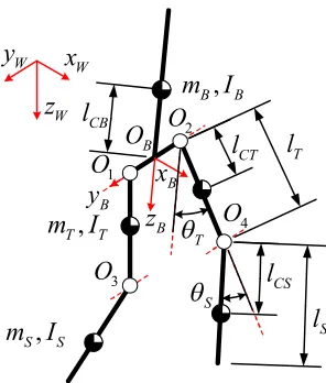
199
origin is set at the midpoint between two hip joints, as shown in Figure 3.
,
B B
m I
,
T T
m I
,
S S
m I
B
x
B
z
B
y
CB
l
CT
l
CS
l
T
l
S
l
W
x
W
z
W
y
B
O
1
O
2
O
3
O
4
O
T
S
201
Figure 3. Parametric model of a human body used in this study
202
where
m
B,m
T , andm
Sare the masses of components B, T, and S, respectively;I
B,I
TandI
S203
are the rotational inertia at their mass center on the coordinate axis
y
B;l
T andl
S are length of204
thigh and shank, respectively;
l
CB,l
CT, andl
CS are distances from the mass centers of B, T, and S,205
respectively, to the coordinate origin
O
B, hip joint, and knee joint, respectively. There are many206
relevant discussions on the calculation of body dimensions and inertial parameters [22]. In this study,
207
a male subject of 75kg weight and 1.75m height is used as an example. The respective parameters are
208
listed in Table 1.
209
Table 1. Parameters of the simplified human dynamic model.
210
T
m
(kg)S
m
(kg)T
I
(
kg mm
2)S
I
(
kg mm
2)T
l
(mm)
S
l
(mm)
CT
l
(mm)
CS
l
(mm)9.69 5.21 5
1.39 10 5
1.03 10 424 422 187 217
2.3.2. Inverse dynamics
211
Human walking process includes several states, which can be reduced to (i) single support, (ii)
212
double support, and (iii) double off-the-ground position. Given a variety of restraints on the feet at
213
different states, the dynamic models are also different. Commonly, it is necessary to introduce a
finite-214
state-machine (FSM) to select the dynamic equations corresponding to the respective states.
215
However, such switching of dynamic equations can provide discontinuous and biased outputs,
216
leading to the motion control instability. Moreover, slight sensing errors made in some non-relevant
217
joints may cause drastic fluctuations to the multi-body inverse dynamics. For example, the angle
218
fluctuations of the supporting ankle may cause a high acceleration of the trunk, and noise signals will
219
submerge the curves of joint torques. To solve the above problems, we transform the integral inverse
220
dynamics of the whole body into that of two separate legs, thereby shortening the kinematic chain
221
and reducing some local disturbances. Then, according to the linear superposition principle of force
222
acting on the rigid-body system, the inverse dynamics of a single leg is further factorized into the
223
mass-induced joint torques and foot contact force (FCF)-induced joint torques.
H
x
H
z
x
CT,
z
CT
x
CS,
z
CS
Wx
W
z
W
y
W
O
TS
(a)
T
S
Fy
Fx
F
Fz
F
2 T
2 S
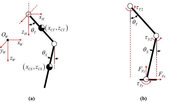
(b)
Figure 4. Simplified dynamic model of a single leg. (a) Model to determine joint torque induced by mass forces; (b) Model to calculate joint torque induced by foot contact forces.
In the calculations of mass-induced joint torques, the foot contact force is neglected, and the leg
225
is considered to be suspended to component B by the hip joint, where the coordinate origin is set, as
226
shown in Figure 4(a). This is a two-bar dynamic model with floating pedestals. The Lagrange method
227
is used to solve the inverse dynamics via Equation 4. More details on the calculation of kinetic energy
228
K and potential energy P are given in Appendix A.
229
1
1
d
(
)
(
)
d
d
(
)
(
)
d
TT T
S
S S
K
P
K
P
t
K
P
K
P
t
(4)
In the estimation of FCF-induced joint torques, the foot end touches the ground while the upper
230
end of the leg supports the entire trunk. Ignoring the mass, we can calculate the joint torque via the
231
static equilibrium equation, as shown in Figure 4(b). FCF values, including
F
Fx,F
Fzand
Fy , are232
measured, and the force balance equations are solved to derive the hip
T2 and knee
S2 joint233
torques
234
2
2
(
cos
cos
)
(
sin
sin
)
cos
sin
T Fx T T S S Fz T T S S Fy
S Fx S S Fz S S Fy
F
l
l
F
l
l
F l
F l
(5)
Finally, the mass- and FCF-induced joint torques are summed to obtain the total joint torque of
235
the hip and knee.
236
1 2
1 2
=
=
T T T
S S S
(6)3. Sensor system design
237
The sensor system is designed to measure all signals required for solving IDA equation. The
238
motion capture system is instrumental in the analysis of human body motion, yet its subject has to
239
stay in a limited area. Once the camera or force plate ranges are exceeded, or the marker points on
240
the subject are covered, the outputs will be invalid. We cannot rely on the motion capture system to
241
provide motion data for controlling the exoskeleton. Instead, we have to design a new sensing system
242
to meet the requirement of portability and simplicity.
According to Equations 4 and 5, the required data include the trunk (component B) posture,
244
acceleration of hip joints, and foot contact forces (FCF). To avoid misalignment of the sensor and
245
wearer’s discomfort, no direct measurements from a human body are used. Instead, the entire sensor
246
system is integrated into the exoskeleton structure to measure the motion information of the
247
exoskeleton, and then, according to the man-machine motion mapping, the human body motion data
248
are derived. The motion mapping is ensured by the structural design, which description can be found
249
elsewhere [23] and is omitted here for brevity. The composition of the sensor system is described
250
below.
251
3.1. Overall hardware architecture
252
The central controller is B&R PLC (Programmable Logic Controller by B&R Industrial
253
Automation GmbH, Austria) in the back frame. The data of inertial measurement unit (IMU) are read
254
through the RS-232 bus with a sample rate of 100Hz. The linear displacement sensors (LDS) placed
255
in hip and knee joints, as well as 1D and 3D force sensors in the sole, are connected to AD converter
256
with a sample rate of 1kHz. All data acquired by PLC are sent to PC in the real-time scale via EtherNet
257
bus.
258
IMU
Hip joint
Knee joint
Shoe PC
A
na
lo
g
si
g
n
a
ls
R
S
-2
3
2
LDS1
LDS2
1DFS1
3DFS 1DFS2
E
th
er
n
et
Body Controlor
259
Figure 5. Hardware system of APAL
260
3.2. The trunk posture and acceleration of hip joints
261
To assess the trunk posture and acceleration of hip joints, a certain adaptation of IMU was
262
required. Since it is fixed in the exoskeleton back frame, which is securely connected to the human
263
trunk, the human trunk and exoskeleton postures are approximately the same in the sagittal plane,
264
with disregard of minor wearing mismatch errors. As shown in Figure 6, the axis of IMU is set parallel
265
to the body coordinate axis, and IMU can directly provide the attitude IMU
=
Wroll pitch yaw
,
,
266
in the WCS, angular velocity IMU
=
,
,
Broll pitch yaw
, and acceleration
267
=
,
,
IMU IMU IMU IMU
B
a
B
x
By
B
z
of IMU in the body coordinate system (BCS). The angular acceleration
268
IMU
B
of IMU in BCS can be obtained via the first-order difference of
IMU
B
. To improve the
269
smoothness and reduce the high-frequency noise induced by quantization error, interpolation and
270
low pass filter are used.
The acceleration W
x
H WH
z
of the hip joint in WCS cannot be measured directly by IMU272
because the two do not coincide, but they can be derived through kinematic relations. The
273
acceleration B
a
IMUobtained by IMU is firstly converted from BCS to WCS asWa
IMU
BtoWR
Ba
IMU,274
where BtoW
R
is the rotation matrix for BCS –WCS conversion. Let the coordinates of IMU in BCS be275
BIMU
P
, and those in WCS beWP
IMU
. Thus, the coordinate of the left hip joint in BCS isB
P
H
, and that
276
in WCS should be W
P
H
BtoWR
(
BP
H
BP
IMU)+
WP
IMU . The acceleration in WCS is277
IMU
W W BtoW B B W
H H H IMU
a
P
R
(
P
P
)+
a
. Here, BtoWR
is the second derivative of the278
rotation matrixBtoW
R
. The required Wx
H and WH
z
are components of Wa
H
on-axis
x
W andz
W279
, respectively.
280
LH
LK RH
RK
IMU
W y
W x zW B
z B x
B y IMU
x
IMU
z
,
IMUy IMUy
281
Figure 6. Trunk posture sensing with IMU and the limb attitude definition
282
3.3. The angles of hip and knee joints
283
The angle of human hip and knee joints are not measured directly but are derived from the
284
respective measurements of the exoskeleton. The displacement signals
s
Hands
K from LDSs are285
converted into hip and knee joint angles
H and
K, according to the geometry of the mechanical286
joints, as shown in Figure 7. The angular velocities
H and
Kare obtained via the first-order287
differences of
H and
K. Similarly, the angular accelerations
H and
K are obtained from the288
first-order differential of
H and
K.289
290
(a)
(b)
Figure 7. Exoskeleton joint geometry and angle measurements for (a) hip joint; (b) knee joint.
291
Figure 8 shows a group of actual curves constructed via in-situ running measurements. The
292
stroke range of the linear displacement sensor is 0~73mm, corresponding to the knee joint angle range
293
of 0~135°, and that of hip joint of -15~150°. We can see that for the in-situ running, the hip and knee
294
joints’ angles varied from 38° to 65° and from 60° to 100°, respectively. Thus, the hip and knee joints
295
did not reach the stroke limit.
297
Figure 8. Joint information of exoskeleton robot, hip and knee cylinder displacement
s
H,s
K; hip and knee298
joint angle
H,
K299
Next, based on the man-machine motion mapping, human hip and knee joint angle can be
300
calculated. Since the exoskeleton knees are rigidly connected to human arches, while ankle axes of
301
the exoskeleton and human body are nearly coaxial, the human ankle coordinates in BCS are nearly
302
the same as those of the exoskeleton. This can be expressed as follows:
303
sin(
)
sin(
)
sin(
)
sin(
)
cos(
)
cos(
)
cos(
)
cos(
)
F Te He Se Ke He T H S K H
F Te He Se Ke He T H S K H
x
l
l
l
l
z
l
l
l
l
(7)
where
He and
Ke are hip and knee joint angles of the exoskeleton;l
Teandl
Seare lengths of304
thigh and shank of exoskeletons, which are 450 and 440 mm, respectively;
l
T andl
S are lengths of305
components T and S of the simplified human model, which are 424 and 422 mm, respectively.
306
Equation 7 allows one to derive joint angles of the human body
H and
K, as well as
H ,
K,
H307
, and
K, as shown in Figure 9.308
Here we manually adjust the thigh and shanks length of the exoskeleton to be slightly smaller
309
than those of the wearer. When the wearer stands straight, the exoskeleton is slightly squatting. This
310
helps to avoid the dead point when the knee joint approaches 0 degrees and does not affect the motion
311
mapping. The results obtained show that the human knee joint angle is 16-53°, the angular velocity
312
is about -300-300°/s, the angular acceleration is -3500-15400°/s2, and the hip joint is -15~81°, the
313
angular velocity is about -540~545°/s, and the angular acceleration is -5700-27000°/s2. It can be seen
314
that the joint angular velocity obtained from the numerical difference is relatively smooth, but the
315
angular acceleration exhibits a sharp variation caused by a touchdown impact.
316
317
Figure 9. Joint information of human lower limbs, hip and knee angle, angular velocity, and angular
318
acceleration
3.4. Foot contact forces (FCFs)
320
A special shoe is developed to measure FCF in the sagittal plane. There are three components of
321
FCF, which include
F
Fxin the front-rear direction,F
Fzin the up-down direction, and torqueT
Fy322
on the dorsiflexion axis. The force condition of the sole is complex. On the one hand, there are many
323
contact states on the sole during exercise, such as heel strike, full foot landing, forefoot landing, and
324
toe landing, etc., while the ground unevenness can also cause unpredictable deformation of the sole.
325
On the other hand, the rotational freedom of the human toe joint is required for walking stability and
326
energy saving [24], so the sole should be flexible. Thus, the double-layer elastic steel sole structure
327
was designed, as shown in Figure 10.
328
Roller rows
Compression sensor
Three-dimensional force sensor
Carbon fiber plate Top plate
Bottom plate
Fy
T
Fx F
Fz F
329
Figure 10. Foot force measurement device.
330
The upper steel plate is connected to the human foot, while the lower steel plate is connected to
331
the exoskeleton, and three force sensors couple by the two layers. Under the arch, a solid carbon fiber
332
plate is used to reinforce the flexible steel plate to increase its stiffness, which forms a strong support
333
for the arch, while the area under the toe joint is not provided with a carbon fiber plate. When the toe
334
joint rotates, the upper and lower two layers of elastic steel plate can follow the plantar deformation.
335
Regarding the choice of sensor placement, both the single- and multi-sensor solutions have been
336
used. Authors [25] introduced an integrative force sensor dedicated to FCF measurement, which
337
combines high integration with high accuracy. However, the sensor should be strong enough to
338
withstand large torque during heel/ toe landing, which will increase the size and weight of the sensor.
339
Meanwhile, the sole is usually set as a rigid body to avoid any damage induced by the local distortion.
340
This prevents the toe joint from bending, which deteriorates the wear comfort. This makes the
multi-341
sensor solution more preferable [26], since the footplate bears a smaller bending torque and can be
342
made lighter and thinner. However, the internal stress is easily generated between the sensors,
343
causing zero drift and other errors.
344
The proposed design is a combination of one 3D force sensor and two 1D force sensors. A 1D
345
force sensor with a high overload margin is set under the heel to measure GRF
F
z1on the heel. This346
sensor can directly withstand the large impact load during the heel strike. A 3D force sensor is
347
arranged slightly behind the toe joint, and the sensor can obtain up-down direction force
F
z2and348
front-rear direction force
F
x2. After the heel is off the ground, the toe joint begins to bend, and the349
pressure center is transferred to the toe. A 1D force sensor is placed under the toe to measure the
350
supporting force
F
z3. The sensor layout and force analysis model are shown in Figure 11. When using351
multiple force sensors to measure the same object at the same time, if there is an over-constraint in
352
the mounting structure, it is likely to cause internal stress and zero-drift errors. Hence, a special
353
treatment of the force sensor connector is performed. The bottom of 3D force sensors is fixed to the
354
lower elastic steel plate, while the upper end is connected with the upper plate through a 1DOF hinge,
355
releasing the constraint of the vertical axial rotation. Two 1D force sensors are connected to the upper
356
plate through a spherical hinge with three DOFs and a sliding pair with one DOF. Thus, the 1D force
357
sensor bears only the axial tensile and lateral forces, in order to avoid the disturbance of the
rear direction horizontal force measurement. The sliding pair on the 1D force sensor under the toe
359
has a long slide. When the toe joint bends, the upper and lower layers of elastic steel plates will be
360
subjected to pressure. The needle roller rows will roll along the slide to prevent the motion
361
interference and ensure the activity degree of the toe joint.
362
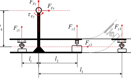
1 z
F
F
z2F
z32 x
F
1
l
l
23
l
4l
FxF
FzF
Fy
363
Figure 11. Synthesis of multiple force sensor signals on the sole.
364
For computational purposes, we synthesize the force signals obtained from the force sensors at
365
the ankle joint. The resultant forces can be calculated based on the location of the force sensors.
366
2
1 2 3
2 4 1 1 2 2 3 3 Fx x
Fz z z z
Fy x z z z
F
F
F
F
F
F
F l
F l
F l
F l
(8)Signals from the sensor and the resultant force are shown in Figure 12. One can see that during
367
in-situ running, the toe first touches the ground, so the force
F
z3from the force sensor below the toe368
is firstly generated. When
F
z1 from the force sensor below the heel is generated, this indicates that369
the entire foot is on the ground. The following is the push-off process. One can see that the resultant
370
force in the vertical direction is significantly higher than the wearer’s gravity force, pushing the body
371
to accelerate upwards and leap. Until the overall toe force drops to zero, the foot leaves the ground
372
and switches to the swing phase. At this stage, FCF should be zero, but the exoskeleton robot power
373
system is not turned on during the experiment, so the wearer needs to bear a part of the exoskeleton
374
leg weight. Therefore, the foot force in the vertical direction during the swing phase is negative. This
375
demonstrated that the foot force-measuring device is more adaptable to different contact states of a
376
foot and can reliably measure the human foot contact force in both support and swing phases.
377
0s 0.5s 1s 1.5s 0 500 1000 0 500 1000 0 500 1000 0 500 1000 1 z F 2 x F 2 z F 3 z F 1 z F 2 x F 2 z F 3 z F Fx F Fz F Fy
0s 0.5s 1s 1.5s
0s 0.5s 1s 1.5s 0s 0.5s 1s 1.5s
Figure 12. (a) Force signals from each sensor on the left foot; (b) resultant force signals on the left foot; (c) force
379
signals from each sensor on the right foot; (d) resultant force signals on the right foot.
380
3.5. Human joint torque solution
381
Using the above sensing system, all parameters required for solving the human inverse
382
dynamics equation are obtained. The mass-induced torques at hip and knee joints
T1 and
S1 can383
be obtained via Equation 4, as shown in Figure 13(a). The FCF-induced torques
T2and
S2 can be384
derived via Equation 5, as shown in Figure 13(b). The resultant joint torque
Tis calculated via385
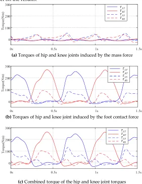
Equation 6, as shown in Figure 13(c). So far, the human joint torque calculation is accomplished. From
386
the results, we can see that in the support phase, the FCF-induced joint torque is far higher than the
387
mass-induced one. According to Equation 5, FCF and the joint angles have a more significant
388
influence on the result. In the swing phase, the foot contact force is small, and the mass-induced joint
389
torque becomes the main component. According to Equation 4, the inertial parameters of human
390
limbs, the acceleration at hip joints, and the joint angle, angular velocity, and angular acceleration
391
exert a strong effect on the results.
392
0s 0.5s 1s 1.5s
0 100 200 300
T
o
rq
u
e(
N
m
)
LT
RT
LS
RS
393
(a) Torques of hip and knee joints induced by the mass force
394
0s 0.5s 1s 1.5s
0 100 200 300
T
o
rq
u
e(
N
m
)
LT
RT
LS
RS
395
(b) Torques of hip and knee joint induced by the foot contact force
396
0s 0.5s 1s 1.5s
0 100 200 300
T
o
rq
u
e(
N
m
)
LT
RT
LS
RS
397
(c) Combined torque of the hip and knee joint torques
398
Figure 13. Human joint torque calculated from in-situ running
399
4. Contrast experiments
400
To verify the overall accuracy of the human joint torque derived from the integrated sensor
401
system of the exoskeleton robot and the proposed IDA equations, we used the commercial motion
402
capture system developed by Motion Analysis Corporation (USA) to synchronously obtain the body's
403
motion data and joint torque, as shown in Figure 14.
Cameras
Force plates Marker points Exoskeleton
405
Figure 14. Experiment environment.
406
Two evaluation indicators are used. The first one is the root mean square error (RMSE), which
407
can quantitatively evaluate the calculation error.
408
2 1
[
]
N
EXOk MAk k
RMSE
N
(9)The second one is the correlation coefficient R, which reflects the similarity between two curves.
409
1 1 1
2 2
2 2
1 1 1 1
1
1
1
n n n
EXOk MAk EXOk MAk
k k k
n n n n
EXOk EXOk MAk MAk
k k k k
n
R
n
n
(10)
-100 0 100
H
ip
t
o
rq
ue
(N
m
)
Er
ro
r
o
f
h
ip
t
o
rq
u
e
(N
m
)
Left hip joint torque (Exoskeleton VS Motion Capture)
-100 0 100
Exos keleton Motion Capture Error
-100 0 100
Stretch and squat March Run Jump
K
n
ee
T
or
qu
e
(N
m
)
Er
ro
r
o
f
k
ne
e
to
rq
u
e
(
N
m
)
0s 10s 20s 30s 40s 50s 60s 70s 80s
Exoskeleton Motion Capture Error -200
0s 10s 20s 30s 40s 50s 60s 70s 80s
-100 0 100
Left knee joint torque (Exoskeleton VS Motion Capture)
410
Figure 15. Comparison of two torque outputs of left leg from the motion capture system and the exoskeleton
411
robot.
According to the instructions of the motion capture system, the wearer pastes the marker points
413
to his/her body, connects the exoskeleton robot, and performs squatting, walking, running and
414
jumping exercises in sequence on the force plate of the motion capture system for 10, 20, and 10 times,
415
respectively. The motion capture system and the exoskeleton robot system collect data
416
simultaneously, and the joint torques of the left and right legs of the human body are calculated, as
417
shown in Figures 15 and 16.
418
Among four actions: squatting, walking, running, and jumping, each action is repeated for ten
419
times, and the statistical results obtained are shown in Table 2.
420
Table 2. RMSE (E) and correlation coefficient (R) for two outputs from different limb joints in different gaits
421
for the left leg.
422
Sub
Squatting Walking Running Jumping
Hip Knee Hip Knee Hip Knee Hip Knee
E R E R E R E R E R E R E R E R
G 1 7.1 0.93 9.8 0.96 17.1 0.75 8.8 0.66 52.5 0.77 22.7 0.93 29.7 0.81 14.7 0.97 G 2 7.8 0.74 8.2 0.99 14.2 0.88 11 0.81 58.8 0.89 15.1 0.81 18.6 0.87 13.2 0.97 G 3 10.7 0.81 9 0.98 13.5 0.88 10.1 0.71 37.1 0.69 30.2 0.94 25.5 0.85 12.5 0.98 G 4 9.2 0.92 7.6 0.99 17.3 0.85 19.8 0.62 37.5 0.75 29.3 0.85 31.3 0.83 11.1 0.98 G 5 9.4 0.9 6.9 0.99 19.9 0.9 20.7 0.07 39.5 0.67 23.8 0.93 54.8 0.31 15.8 0.97 G 6 8.3 0.95 11.4 0.98 11 0.64 13 0.84 36.5 0.78 27.9 0.87 76.2 -0.4 12.2 0.97 G 7 8.9 0.94 8.1 0.99 12.2 0.89 14.8 0.71 39.7 0.78 23 0.91 54.4 0.15 16.2 0.97 G 8 9.5 0.9 9.3 0.99 12.3 0.84 23.1 0.43 36.8 0.77 28.9 0.94 68.1 -0.3 13.8 0.98 G 9 10.1 0.93 10.5 0.98 13.7 0.76 16.5 0.41 47.4 0.85 18.4 0.92 20.9 0.94 15.3 0.97 G 10 10.4 0.95 6.7 0.99 13.1 0.87 21.5 0 51.7 0.83 17.6 0.88 63.4 -0.3 10.9 0.98 Mean 9.14 0.9 8.75 0.98 14.4 0.83 15.9 0.53 43.8 0.78 23.7 0.9 44.3 0.38 13.6 0.97 SD 1.15 0.07 1.54 0.01 2.78 0.08 5.16 0.29 8.15 0.07 5.36 0.04 21.4 0.55 1.9 0.01
At the squatting stage, the hip and knee joint data exhibit a good fit. The mean RMSE is less than
423
10 Nm, and the correlation coefficient exceeds 0.9, indicating a high similarity of the waveforms.
424
At the walking stage, the matching degree of the knee joint data is significantly reduced, and the
425
correlation coefficient even becomes negative at times. This may be attributed to the fact that the knee
426
joint at the walking stage is almost straight and stays at the dead point support state, so the torque is
427
small at this time, while the relative interference from each link of the system is relatively large. The
428
hip joint at the walking stage mainly controls the trunk attitude, while the torque is significant, and
429
the error is relatively small.
430
At the running stage, the hip and knee joint torques are significantly higher than those at the
431
walking stage, so the corresponding RMSE is significantly increased, but the waveform similarity is
432
better than that at the walking stage. This phenomenon strongly indicates that the proposed IDA
433
process is similar to that of the motion capture system, but the difference mainly lies in the model of
434
human body. After wearing the exoskeleton robot, the marker point that should be placed behind the
435
pelvis of the wearer can only be moved onto the exoskeleton. Otherwise, it will be covered by the
436
exoskeleton. This unavoidable defect will cause artificial changes to the model of the human body
437
and deteriorate the final result.
438
At the jumping stage, the joint torque is significantly higher than that at other stages. The RMSE
439
of the hip joint is slightly higher than that of the running stage, but the correlation coefficient is
440
reduced. This implies that the pulse load and high-speed balancing adjustment make the hip joint
441
torque fluctuate rapidly, thereby, reducing the waveform similarity. However, there is no significant
442
increase in the RMSE when the torque is significantly raised, indicating that when the joint torque of
443
the human body is large, the relative error is likely to be reduced. The knee joint data further confirm
444
this trend. At the same time, although the torque of the knee joint is large, low RMSE (13.6 Nm) and
445
high R (0.97) indicate that the knee joint error is minimal. This allows one to assume that FCF-induced
torque is significantly higher than the mass-induced component. The FCF component is controlled
447
by the measurement accuracy of FCF and attitude angle, being less affected by the disturbance
448
induced by the inertial acceleration, joint angular velocity, and angular acceleration derived by the
449
multi-order differential. Therefore, it is easier to obtain a high precision, which is also confirmed by
450
the results obtained at squatting and running stages.
451
-100 0 100
H
ip
t
o
rq
u
e
(N
m
)
E
rr
o
r
o
f
h
ip
t
o
rq
u
e
(N
m
)
Right hip joint torque (Exoskeleton VS Motion Capture)
-100 0 100
Exoskeleton Motion Capture
Error
-100 0 100
Stretch and squat March Run Jump
K
n
e
e
T
o
rq
u
e
(N
m
)
E
rr
o
r
o
f
k
ne
e
t
o
rq
u
e
(
N
m
)
0s 10s 20s 30s 40s 50s 60s 70s 80s
Exoskeleton Motion Capture
Error
-200
0s 10s 20s 30s 40s 50s 60s 70s 80s
-100 0 100
Right knee joint torque (Exoskeleton VS Motion Capture)
452
Figure 16. Comparison of two torque outputs of right leg from the motion analysis system and the exoskeleton
453
robot.
454
Table 3. RMSE (E) and correlation coefficient (R) for two outputs from different limb joints in different gaits
455
for the right leg.
456
Sub
Squatting Walking Running Jumping
Hip Knee Hip Knee Hip Knee Hip Knee
E R E R E R E R E R E R E R E R