R E S E A R C H
Open Access
Decoupled signal detection for the uplink
of massive MIMO in 5G heterogeneous
networks
Leonel Arévalo
1*, Rodrigo C. de Lamare
1, Martin Haardt
2and Raimundo Sampaio-Neto
1Parts of this paper have been published at CAMSAP 2015
Abstract
Massive multiple-input multiple-output (MIMO) systems are strong candidates for future fifth-generation (5G) heterogeneous cellular networks. For 5G, a network densification with a high number of different classes of users and data service requirements is expected. Such a large number of connected devices needs to be separated in order to allow the detection of the transmitted signals according to different data requirements. In this paper, a decoupled signal detection (DSD) technique which allows the separation of the uplink signals, for each user class, at the base station (BS) is proposed for massive MIMO systems. A mathematical signal model for massive MIMO systems with centralized and distributed antennas in heterogeneous networks is also developed. The performance of the proposed algorithm is evaluated and compared with existing detection schemes in a realistic scenario with distributed antennas. A sum-rate analysis and a computational cost study for DSD are also presented. Simulation results show an excellent performance of the proposed algorithm when combined with linear and successive interference cancellation detection techniques.
Keywords: Massive multiple-input multiple-output (MIMO) systems, Heterogeneous networks, Fifth-generation (5G) cellular networks, Decoupled signal detection (DSD)
1 Introduction
Large-scale multiple-input multiple-output (MIMO) sys-tems, also known as massive MIMO, are a promising technology which use a large number of antennas to serve a high number of user terminals at the same time with-out requiring extra bandwidth resources [1–4]. This new greater scale version of traditional MIMO systems, where a restricted number of antennas is used, is designed to exploit the benefits of extra degrees of freedom obtained by the use of more antennas [5]. Massive MIMO can increase the spectral efficiency 10 times or more when compared with its predecessor [6]. In the Long Term Evo-lution (LTE) standard [7], which uses traditional MIMO systems, with as many as eight antenna ports at the base station (BS), and operates in the frequency-division
*Correspondence: [email protected]
1Center for Studies in Telecommunications (CETUC), Pontifical Catholic University of Rio de Janeiro (PUC-Rio), Rio de Janeiro, Brazil
Full list of author information is available at the end of the article
duplex (FDD) mode, the users estimate the channel response and feed it back to the BS. For massive MIMO with hundreds of antenna elements, this might not be feasible, due to the large number of channel coefficients that each user needs to estimate being proportional to the number of the antennas at the BS. In this paper we focus on the uplink, the reason is that the most natu-ral transmission mode to operate in massive MIMO is the time-division duplexing (TDD) mode, where a reci-procity between the uplink and downlink channels can be obtained, if we use appropriate calibration techniques to combat the distortions induced by hardware imperfec-tions, since the base station can offer more processing resources aimed at estimating the channel between users’ terminals and the BS. On the downlink, it is possible to use different precoding schemes to mitigate the interfer-ence for the received signals at the mobile users. Such precoding schemes rely on the channels estimated on the uplink.
One of the main research challenges of massive MIMO is to develop computationally simple ways to process the large number of signals received at the BS. The inter-ference between antennas and users, propagation effects such as correlation, path loss and shadowing, thermal noise and signal degradation due to the hardware imper-fections need to be suppressed. Linear detection tech-niques such as maximum radio combining (MRC) and zero forcing (ZF) are a good option in terms of computa-tional complexity; however, their performance is not com-patible with the growing demand for high data rates. The performance of linear detectors can be improved using some nonlinear sub-optimal detector based on succes-sive interference cancellation (SIC) [8], e.g., multibranch SIC (MB-SIC) [9, 10] and multifeedback SIC (MF-SIC) [11]. However, SIC-based detectors have a considerable computational cost for high-dimensional systems. If all signals from all active users are coupled in the detec-tion process, the BS could spend unnecessary processing resources since some types of users might not require a very high performance.
In the next generation of wireless communication sys-tems [12], it is expected that a large number of users with different configurations and requirements are connected to the network. Therefore, it is necessary to design hetero-geneous networks capable of interconnecting the different user types with each other [13]. The received signals from this large number of connected devices such as metering equipment, sensors, environmental monitoring devices, health care gadgets, security management products, smart grid components, smart phones, and tablets need to be separated in order to detect the transmitted information according to their different data requirements. In this context, distributed antenna systems (DAS) with massive MIMO are a promising alternative for the 5G cellular architecture [14], where the BS will be equipped with a large number of antennas and some remote antenna arrays or radio heads will be distributed around the cell and connected to the BS via optical fiber. The signals asso-ciated with different remote antenna arrays are processed at the BS. DAS have low path loss effects and improve the coverage and the spectral efficiency [15, 16]. The energy consumption of users is reduced and the transmission quality is improved due to the shorter distances between users and some remote antenna arrays. For this vision of 5G wireless networks, which includes a combination of massive MIMO, heterogeneous networks, and distributed antenna systems, efficient signal processing techniques at the BS are necessary.
In this paper, we propose an algorithm for the uplink of massive MIMO systems to separate the combined received signal of all users at the BS into independent signals for each user class. The proposed decoupled sig-nal detection (DSD) applies a decomposition into multiple
independent single user class signals, where all users in a class have the same data requirements and a com-mon complex modulation. Assuming that the channel state information (CSI) was previously estimated, DSD employs a common channel inversion and QR decom-position to decouple the received signal. Applying the proposed algorithm, the computational cost of the signal processing is reduced and it is possible to have flexibil-ity on the detection procedures at the BS. A signal model for heterogeneous networks with different classes of users and an arbitrary configuration of centralized antenna sys-tems (CAS) and DAS is also introduced in this paper. A sum rate analysis and a computational complexity study for the proposed DSD are presented. The performance of the proposed scheme is evaluated in a realistic sce-nario with propagation effects and compared with existing approaches.
The remainder of this paper is organized as follows. In Section 2 the proposed massive MIMO signal model is presented. The proposed DSD scheme is presented in Section 3. The sum rate analysis for the DSD scheme is described in Section 4. Section 5 presents simulation results. Section 6 gives the conclusions.
2 Massive MIMO signal model
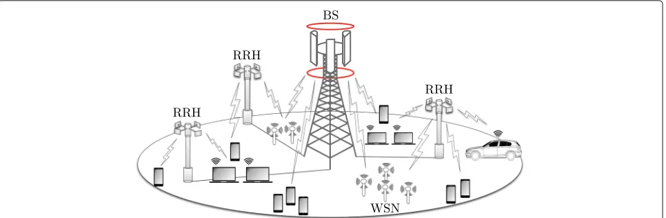
Fig. 1Heterogeneous wireless network: base station (BS), remote radio head (RRH), and wireless sensor networks (WSN)
the classn. The total number of active users is given by K = Nn=1 | Cn |. The kth user in the nth user class transmits data divided intoNtk,nsub-streams throughNtk,n
antennas, whereNr Nt =
N
n=1
|Cn|
k=1Ntk,n andNtis
the total number of transmit antennas. The received sig-nal vector at the BS from all active users in all user classes is given by kth user of thenth user class, at one time slot taken from a complex constellation, denoted byA= {a1,a2,. . .,aO}. Each symbol hasMbits andO= 2M. The vectornis an
Nr×1 zero mean complex circular symmetric Gaussian
noise vector with covariance matrix Kn = E
nnH =
σ2
nI. Moreover, H¯k,n is the Nr × Ntk,n channel matrix
of the kth user in the class n with elements h¯(k,n)i,j
cor-responding to the complex channel gain from the jth
transmit antenna of thekth user to theith receive antenna. For the antenna elements located at the BS and at each remote radio head, the D+ 1 sub-matrices of H¯k,n =
using the Kronecker channel model [18], expressed by
¯
where G(j)k,n has complex channel gains between thekth user and thejth radio head, obtained from an indepen-dent and iindepen-dentically distributed random fading model whose coefficients are complex Gaussian random vari-ables with zero mean and unit variance. R(j)r and Rtk,n
denote the receive correlation matrix of the jth radio head and the transmit correlation matrix, respectively. The components of the correlation matricesR(j)r andRtk,n
are modeled as a variation of the model described in equations (3)-(5) of reference [18]:
R=
whereNais the number of antennas andρis the corre-lation coefficient of neighboring antennas (ρ = ρtx for
the transmit antennas andρ = ρrx for the receive
anten-nas), i.e., a decaying of the correlation index with antenna separation faster than exponential was adopted. Note that
ρ = 0 represents an uncorrelated scenario and ρ = 1
implies a fully correlated scenario. TheNr×Nr diagonal matrixϒk,nrepresents the large-scale propagation effects for the userk of the user classn, such as path loss and
where the parameters γk,nj denote the large-scale prop-agation effects from the kth user to the jth radio head described by
Hereαjk,nis the distance based path-loss between each user and the radio heads which is calculated by
where Ljk,n is the power path loss of the link associated with the user and thejth radio head,dk,nj is the relative distance between this user and thejth radio head,τis the path loss exponent chosen between 2 and 4 depending on the environment. The log normal random variableβk,nj
which represents the shadowing between userkand the
receiver is given by
βk,nj =10 μk,sϑ
j k,s
10 , (7)
where μk,s is the shadowing spread in decibels and ϑk,sj corresponds to a real-valued Gaussian random variable with zero mean and unit variance. Since the Nr × Ntk,n
composite channel matrix includes large-scale and small-scale fading effects, it can be denoted asHk,n=ϒk,nH¯k,n, and the expression in (1) can be written as
y =
represent the channel matrix and the transmitted symbol vector of all users in the class n, respectively. The received signal vector can be expressed more conveniently as
y = Hs+n, (9)
whereH=[H1 H2. . .HN] ands=
sT1 sT2 . . .sTNT. The symbol vectorsof allNuser classes has zero mean and a covariance matrixKs=E
ssH=diag(p), where the ele-ments of the vectorpare the signal power of each transmit antenna. To maintain a notational simplicity in the subse-quent analysis, we assume that all antenna elements at the users transmit with the same average transmitted power σ2
s, i.e., Ks = σs2I. We assume that the channel matrix
Hwas previously estimated at the BS. From (9) we can
see that the signals arrive coupled at the BS. If we want to use different detection procedures for each user class according to its data requirements, we have to separate the received signal vectoryinto independent received sig-nals for each user class. For the system model presented in this work, when the number of remote radio heads is set to zero, i.e.,D=0, the DAS architecture is reduced to the CAS scheme withNr=NB.
3 Decoupled signal detection
As presented in Section 2, in heterogeneous networks dif-ferent classes of users send parallel data streams, through the massive MIMO channel operating with distributed antennas, which arrive superposed at the BS. In this 5G context, we need to separate the data streams for each category of users efficiently. In this section, we describe the proposed decoupled signal detection (DSD) which
allows us to separate the received signal of thenth user class from the others. To this end, we consider that the process of authentication, identification, and channel esti-mation was already made, i.e, the BS is able to identify the users by classes according to their data requirements. Similar approaches to the proposed algorithm have been proposed for the downlink, such as block diagonalization (BD)-based techniques [19–22]. However, unlike prior work in which downlink BD is used, for the proposed DSD scheme, it is not necessary to use any precoding at the transmit side. The receiver only needs to know the channels between users and receive antennas. More-over, the concept of separating the users with respect to the classes in heterogeneous networks according to its requirements is a new approach. The first steps to con-struct the concept proposed in this paper were presented in [23, 24].
The received signal vector (8) can be written as:
y = Hnsn+ N
m=1,m=n
Hmsm+n, (10)
where Hn andsn are the channel matrix and the trans-mitted symbol vector for thenth user class, respectively. From (10), we can see that thenth user class has inter-user class interference.
3.1 Proposed decoupling strategy
To remove the presence of the other classes of users in the detection procedure for the nth user class, we can employ a linear operation to project the received
sig-nal vector y onto the subspace orthogonal or almost
orthogonal to the subspace generated by the signals of the interfering classes. In DSD, a matrix An is calcu-lated employing a channel inversion method and a QR decomposition [25, 26], in order to decouple thenth user’s class received signal from other user’s class signals. To computeAn, we construct the matrixH˜n excluding the channel matrix of the nth user class in the following form:
number of transmit antennas in thenth user class. After that, the objective is to obtain a matrix An that satisfies the following condition:
AnH˜n=0, ∀n∈(1. . .N). (12)
To compute An, DSD first computes the MMSE
channel inversion of the combined channel matrix H
given by
H† = HHHHH+σ2I−1
= (H¨1)T (H¨2)T . . . (H¨N)T T
where σ2 = σ2
n/σs2,H† ∈ CNt×Nr andH¨n ∈ CNtn×Nr.
Then, the matrix H¨n is approximately in the null space ofH˜n, that is
¨
HnH˜n≈0, ∀n∈(1. . .N). (14)
To decouple the nth user group from the other user
groups, we employ a QR decomposition as described by ¨
Hn=RnQn, ∀n∈(1. . .N), (15)
whereRn ∈ CNtn×Ntn is an upper triangular matrix and
Qn∈CNtn×Nr is a matrix with orthogonal rows and com-posed by approximately orthonormal basis vectors of the left null space ofH˜n. Then we have
QnH˜n≈0. (16)
From (16), we can see thatQnis a good approximation forAn in (12). Using An = Qn as a linear combination with the received signal vector in (10), we have
yn = Any
whereyn∈CNtn×1is the equivalent received signal vector for the user classnand the term QnNm=1
m=nHmsm ≈ 0
represents the residual inter-user class interference. Then, we can transform the received signal vector into parallel single-user class signals as described by
yn= ˇHnsn+nn, ∀n∈(1. . .N), (18)
vector. Note thatH† in (13) could have been provided by the pseudo-inverse ofH. This option satisfies the zero interference constraint in (12); however, it does result in a noise enhancement effect and has a restriction in terms of the dimension, i.e.,Nr≥Nt. The proposed strategy can be used even whenNr <Ntand provides a balance between the inter-user class interference and the noise effects since the noise is taken into account in the computation of (13). Another option to compute a basis for the left null space ofH˜nis performing the SVD transformationH˜n =
˜
Un n˜ V˜Hn, where n˜ ∈CNr×(Nt−Ntn)is a rectangular diag-onal matrix with the singular values ofH˜non the diagonal,
˜
Un ∈ CNr×Nr andV˜Hn ∈ C(Nt−Ntn)×(Nt−Ntn) are unitary matrices. Ifrnis the rank ofH˜nthat corresponds to the number of non-zero singular values, i.e.,rn=rank(H˜n)≤
Nt−Ntn, the SVD can be expressed equivalently as:
˜
VH0,n form an orthogonal basis for the left null space and the null space ofH˜n, respectively. Then, the alternative solution for (12) could be:
An= ˜UH0,n. (20)
Although the matrixU˜H0,neliminates the inter-user class interference effectively, i.e.,U˜H0,nNm=1
m=n
Hmsm = 0, when
we useyn = Qnyin the first approach the noise effects in the detection procedure are mitigated due to the fact that the computation ofQntakes the noise into account. Thus, noise effects are reduced which improves the per-formance, even in the presence of residual interference. In addition, the equivalent channel matrixHˇ1n = ˜UH0,nHn
has dimensions(Nr−r)×Nt as opposed to the matrix
ˇ
H2n=QnHnwhich has dimensionsNtn×Ntn. For this
rea-son the computational complexity of the detector is lower if we use the matrixQn to decouple the received signal vector.
The fact that we obtain a square equivalent channel matrix also allows the possibility of using lattice reduction (LR)-based detectors which have a better performance for square channel matrices [27]. Further, the computational complexity to compute the channel inversion (13) and
N QR decompositions (15) of matrices with dimensions
Ntn ×Nr is much lower than the computational cost of
computingN SVD transformations (19) of matrices with
dimensionsNr×(Nt−Ntn). For these reasons, in this paper
we will focus on the first alternative.
As it will be presented in the next section, the equiva-lent received signal vector in (18) shows that the process in (11)-(17) is an effective algorithm to separate the user classes at the BS and we can consider the data stream of thenth user class as independent of the received signals of the other user classes. In practice, this allows the possibil-ity of using different transmission and reception schemes for each user class. We can now implement the tradi-tional detectors for each class of users separately which also allows the possibility of using more complex detec-tion schemes due to the reducdetec-tion of the dimensions of the matrices that need to be processed. The description of the proposed algorithm is presented in Algorithm 1.
3.2 Detection algorithms
Algorithm 1 :The DSD algorithm
Channel and noise variance estimated with training sequence
(1) Initialization:H,σ
Get the received signal
(2) y=Nn=1Hnsn+n
=Hs+n
Compute the combined channel inversion
(3) H†=HHHHH+σ2I−1
=H¨1 H¨2 . . . H¨N
(4) Do forn=1toN
Applying the QR decomposition
(5) [Rn Qn]=RQ(H¨n)
(6) An=Qn
Compute the equivalent received signal vector
(7) yn=Any
= ˇHnsn+nn
Applying the detection procedures
(8) sˆn=Detector
yn,Hˇn=AnHn
(9) End
Compute the overall estimated signal vector (10) ˆs=sˆT1 sˆT2 . . . sˆTNT
3.2.1 Linear detectors
In linear detectors, the equivalent received signal vector for thenth user classyn ∈CNtn×1is processed by a linear filter to eliminate the channel effects [28]. The two linear detectors considered here are given by
Wχn = lent channel matrix of thenth user class. Note that for the MMSE detector, we consider the autocorrelation matrix of the equivalent noise vector asKnn≈σn2I. As the resid-ual interference is very small, an excellent performance can be obtained with this approximation. The linear hard decision ofsnis carried out as follows:
ˆ
where the function C(x) returns the point of the com-plex signal constellation closest tox. The linear detectors have a lower computational complexity when compared with the non-linear detectors. However, due to the impact
of interference and noise, linear detectors offer a limited performance.
3.2.2 Successive interference cancellation
The successive interference cancellation (SIC) detector for the nth user class in (18) consists of a bank of lin-ear detectors, each detects a selected component sn,i of
sn. The component obtained by the first detector is used to reconstruct the corresponding signal vector which is then subtracted from the equivalent received signal to further reduce the interference in the input to the next lin-ear receive filter. The successively cancelled received data vector that follows a chosen ordering in the ith stage is given by
where hˇn,j correspond to the columns of the channel matrixHˇnandˆsn,jis the estimated symbol obtained at the output of thejth linear detector.
3.2.3 Multiple-branch SIC detection
In the multi-branch scheme [10] for the nth user class, different orderings are explored for SIC, each ordering is referred to as a branch, so that a detector withLbranches produces a set ofLestimated vectors. Each branch uses a column permutation matrixPn. The estimate of the sig-nal vector of branchl,xˆ(l)n , is obtained using a SIC receiver based on a new channel matrixHˇ(l)n = ˇHnP(l)n . The order of the estimated symbols is rearranged to the original order by
ˆ
s(l)n =P(l)n xˆn(l), l=1,. . .,L. (24)
A higher detection diversity can be obtained by selecting the most likely symbol vector based on the ML selection rule, that is
ˆ
sn=arg minyn− ˇHnˆsln 2
,l=1,. . .,L. (25)
Other detectors could be used with the proposed DSD technique and this is up to the designer to choose the detector.
4 Sum-rate analysis
the received signal vector as presented in (18), the sum rate [29] that DSD can offer is defined as
R=
whereKynandKnnare the autocorrelation matrix of the
equivalent received signal vector and the equivalent noise vector of thenth user class, respectively. It is easy to show that (26), can be expressed as
R= mitian symmetric positive-definite square matrix, we have
BnBHn = ¯QnnQ¯Hn, (28)
whereQ¯nis a square unitary matrix,Q¯nQ¯Hn =I, andnis a diagonal matrix whose diagonal elements are the eigen-values of the matrixBnBHn. Then, the reliable sum rate that the system can offer is
R=
Note that the eigenvaluesλi,n in (29) can be obtained
computing the eigenvalues of BHnBn. As mentioned
before, for notational simplicity we assume that Ksn = σ2
sI. When the DSD algorithm is applied, the
equiv-alent noise vector for the nth user class nn =
QnNm=1
m=n
Hmsm+Qnn∈ CNtn×1is not white due to the
residual inter-user class interference. Then its autocorre-lation matrix is given by
Knn =E[nnnHn]=σs2Qn
Finally, the eigenvaluesλi,nin (29) are obtained from the eigenvalues of matrixBHnBngiven by
BHnBn= σ
To compute the sum rate for the received signal vector in (9) when the detection is perform for all user classes together, we suppress the indexnfrom the above analysis and considering thatKs=σs2IandKn= σn2I, we get the
where the values λi are the eigenvalues of the matrix
BHB= σs2 σ2
nH
HH[30]. In Appendix 1, we show that, as well
as the sum rate in (32) when all user classes are detected together, the sum rate in (29) for the proposed algorithm is independent of the detection procedure. However, the lower bound on the achievable uplink sum rate obtained by using linear detectors is different for each detector [31]. In order to analyze the behavior of the lower bound on the sum rate for the proposed scheme, we consider that a linear detector according to (21) is applied to the equiva-lent received signal vector (18) to detect the transmitted symbol vector of the user classn, then we have
˜ ference, the inter-user class interference and the inter-user interference in the user classnin (34) as additive Gaus-sian noise independent ofsk,n, considering (30) and that the channel is ergodic so that each codeword spans over a large number of realizations, we obtain the lower bound on the achievable rate for the DSD algorithm with linear detectors as described in (35).
Then, the lower bound on the achievable rate for the entire system is given by
Rk,n=E
+&&&&wk,n
R= N
n=1
|Cn|
k=1
Rk,n. (36)
For the SIC receiver, each stream is filtered by a lin-ear detector and then, its contribution is subtracted from the received signal to improve the subsequent detection. For each layer the linear filter is recalculated. The perfor-mance of SIC detectors can be improved if we choose the cancellation order as a function of the SINR at the out-put of the linear detector in each layer. The lower bound for the sum rate of the proposed algorithm when a SIC detector is used for each user class, could be calculated updating the expression (35) in each layer, i.e., the values ofwk,nare recalculated for each detected stream.
5 Numerical results
In this section, we evaluate the performance of the pro-posed algorithm with different detectors in terms of the sum rate and the BER via simulations. Moreover, the computational complexity of the proposed and existing algorithms is also evaluated.
5.1 Sum rate
To evaluate the analytic results obtained in Section 4, the sum rate and the lower bounds for the proposed algo-rithm with different detection schemes will be evaluated
considering CAS and DAS configuration assuming perfect
CSI. For the CAS configuration, we employ Lk = 0.7,
τ = 2, the distancedk to the BS is obtained from a uni-form discrete random variable distributed between 0.1 and 0.99, the shadowing spread isσk =3 dB and the trans-mit and receive correlation coefficients areρrx =0.2 and ρtx = 0.4 (whenNtk,n > 1), respectively. For DAS
con-figurations, we consider a densely populated cell, where a fraction of the active users are in the center of the cell and the remaining users are in other locations of the cell. We explore different particular values for the fraction of users in the center and around the cell. Based on that, we choose specific values forNB,D, andQ. For the DAS configura-tion, we also considerLk,jtaken from a uniform random variable distributed between 0.7 and 1,τ = 2, the dis-tancedk,j for each link to an antenna is obtained from a uniform discrete random variable distributed between 0.1 and 0.5, the shadowing spread isσk,j=3 dB and the trans-mit and receive correlation coefficients areρrx =0.2 and ρtx=0.4, respectively.
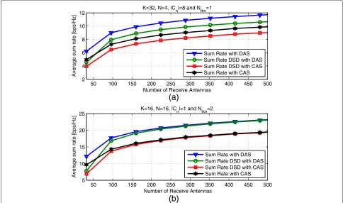
In Fig. 2 we evaluate the sum rate in two different scenarios for the user requirements. In both cases, we fix the SNR = 10 dB and increase the number of receive
antennas. For the DAS configuration, we considerNB =
1/2Nrantennas at the BS. We also considerD=4 arrays of antennas distributed around the cell, each equipped
50 100 150 200 250 300 350 400 450 500 2
4 6 8 10 12
Number of Receive Antennas
Average sum rate [bps/Hz]
K=32, N=4, |C
n|=8 and Ntkn=1
Sum Rate with DAS Sum Rate DSD with DAS Sum Rate DSD with CAS Sum Rate with CAS
50 100 150 200 250 300 350 400 450 500 5
10 15 20 25
Number of Receive Antennas
(b)
(a)
Average sum rate [bps/Hz]
K=16, N=16, |C
n|=1 and Ntkn=2
Sum Rate with DAS Sum Rate DSD with DAS Sum Rate DSD with CAS Sum Rate with CAS
Fig. 2 aSum rate vs number of receive antennas.N= 4,|Cn|=8 users per class,Ntk,n=1 antenna per user.bSum rate vs number of receive
withQ=1/8Nrantennas. For Fig. 2a, we considerN =4 classes of users with| Cn |= 8 users each andNtk,n = 1
antenna per user. We can see that the sum rate of the proposed DSD algorithm is close to the sum rate of the traditional MIMO system and with a low computational complexity on the detection procedures as will be shown in the next subsection. For Fig. 2b, we consider 16 active users in the system and that we need to detect each user independently, i.e.,N=16 classes of users with|Cn|=1 user at each class andNtk,n =2 antennas per user. Under
these conditions, the sum rate of the proposed scheme reaches the sum rate of the traditional MIMO system, especially for a large number of receive antennas. From the plot in Fig. 2, we can see that the sum rate for DAS is higher than that for the CAS configuration.
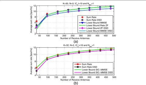
In Fig. 3, we compare the lower bound on the sum rate for different detectors such as, ZF, MMSE, and SIC. We consider the DAS configuration under the same con-ditions as in the previous experiment. For Fig. 3a, we considerN = 3 classes of users with | Cn |= 10 users at each class and Ntk,n = 1 antenna per user. We can
see from the plot that, similarly to the traditional MIMO systems, the lower bound on the sum rate for ZF and MMSE achieves the sum rate whenNrgrows. For Fig. 3b, we considerN =2 classes of users with|Cn |=16 users at each class andNtk,n =1 antennas per user. We can see
that the SIC-MMSE achieves the sum rate and it could be considered optimal in terms of sum rate.
In Fig. 4, we compare the lower bound sum rate versus SNR. We considerN = 8 classes of users with|Cn |=1 user in each class andNtk,n = 8 antennas per user
trans-mitting with high correlation between antennas ρtx =
0.85. We consider the DAS configuration withNB = 96,
D = 4, andQ = 8. We can see from the plot that the
lower bounds for the proposed algorithms are very close to the lower bounds when the detection procedure is car-ried out together for all users. Since ZF DSD separates the user classes by computing a MMSE matrix which takes the noise component into account, it will be the only detector that outperform its coupled counter part.
Except for the ZF-DSD case, there is a small loss in the performance for DSD schemes. However, with the current processor technologies, to use a SIC MMSE in a 256×256 massive MIMO system could be infeasible. By dividing the users into classes of users, the computational com-plexity in the detection procedure decreases significantly and makes the use of the SIC-MMSE and more complex detectors feasible.
5.2 Computational complexity analysis
In this subsection, the computational complexity of the proposed algorithm is evaluated and compared with the
50 100 150 200 250 300 350 400 450 500 4
6 8 10 12
Number of Receive Antennas
Average sum rate [bps/Hz]
K=32, N=2, |C
n|=16 and Ntkn=1
Sum Rate Sum Rate DSD
Lower Bound SIC−MMSE Lower Bound SIC−MMSE DSD 50 100 150 200 250 300 350 400 450 500 2
4 6 8 10 12
Number of Receive Antennas
Average sum rate [bps/Hz]
K=30, N=3, |C
n|=10 and Ntkn=1
Sum Rate Sum Rate DSD Lower Bound MMSE Lower Bound Rate ZF Lower Bound ZF DSD Lower Bound MMSE DSD
(a)
(b)
Fig. 3 aSum rate vs number of receive antennas.N= 3,|Cn|=10 users per class,Ntk,n=1 antenna per user.bSum rate vs number of receive
−100 −5 0 5 10 15 20 25 10
20 30 40 50 60 70 80
SNR [dB]
Average sum rate [bps/Hz]
MMSE ZF ZF DSD MMSE DSD SIC−MMSE SIC−MMSE DSD
Fig. 4Sum rate lower bound vs SNR.N= 8,|Cn|=1 user per class,Ntk,n=8 antennas per user. We consider DAS configuration withNB=96,
D=4, andQ=8
traditional coupled detection schemes, when all user classes are detected together, by counting the number of floating point operations (FLOPs) per received vec-tor y. Different detection schemes are considered such as MMSE, SIC, and MB-SIC. The SIC-based receivers all use MMSE detection. Furthermore, the single-branch SIC and the first branch of the MB-SIC employ norm-based ordering. We consider QPSK modulation; however, the computational cost in these detectors does not change
significantly with the modulation order. The number of FLOPs for the complex QR decomposition of anNtn×Nr
matrix is given in [32] as 16Nr2Ntn−Nt2nNr+1/3N 3
tn
. To compute the number of FLOPs required for the remaining operations, we use the Light-speed Matlab toolbox [33].
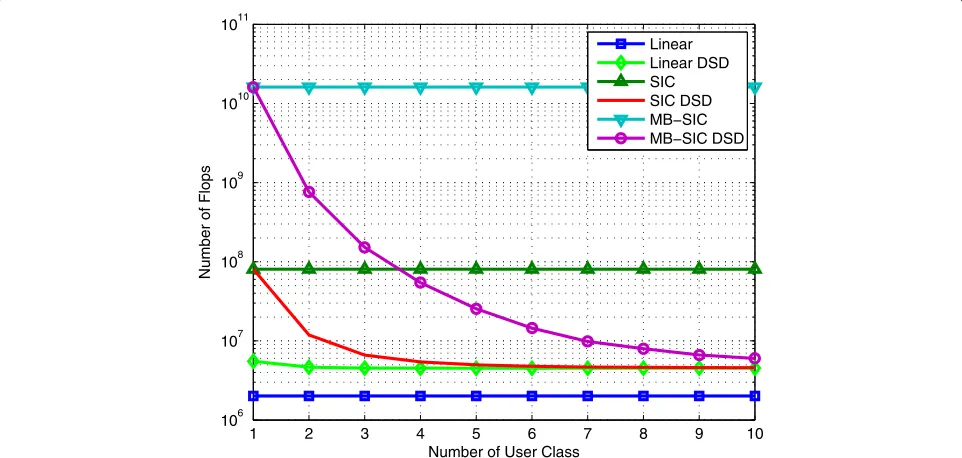
Figure 5 shows the computational complexity versus the number of user classes for different detection algo-rithms. We consider K = 100 active users, Ntk,n = 2
1 2 3 4 5 6 7 8 9 10
106 107 108 109 1010 1011
Number of User Class
Number of Flops
Linear Linear DSD SIC SIC DSD MB−SIC MB−SIC DSD
10 20 30 40 50 60 70 80 90 100 103
104 105 106 107 108 109 1010 1011
Number of Active Users
Number of Flops
Linear Linear DSD SIC SIC DSD MB−SIC MB−SIC DSD
Fig. 6Computational complexity versus number of active user,N=5 classes of user,Ntk,n=2 antennas per user,Nt=KNtk,ntransmit antennas and
Nr=3Ntreceive antennas
transmit antennas per user andNr = 200 receive anten-nas distributed around the cell. We consider an increasing number of classes of users, whenKis not divisible by the number of classes, the number of active users is set to a smaller value so as to allow the division inN classes. We can see from the figure that the complexity of the SIC and the MB-SIC detectors with the DSD algorithm is lower than the SIC and the MB-SIC coupled detectors,
respectively. Furthermore, for receivers with DSD, the computational complexity is reduced as the number of user classes is increased. This fact represents an impor-tant advantage for receivers with DSD, due to the fact that it allows the use of more complex detectors for each user class according to its data requirements.
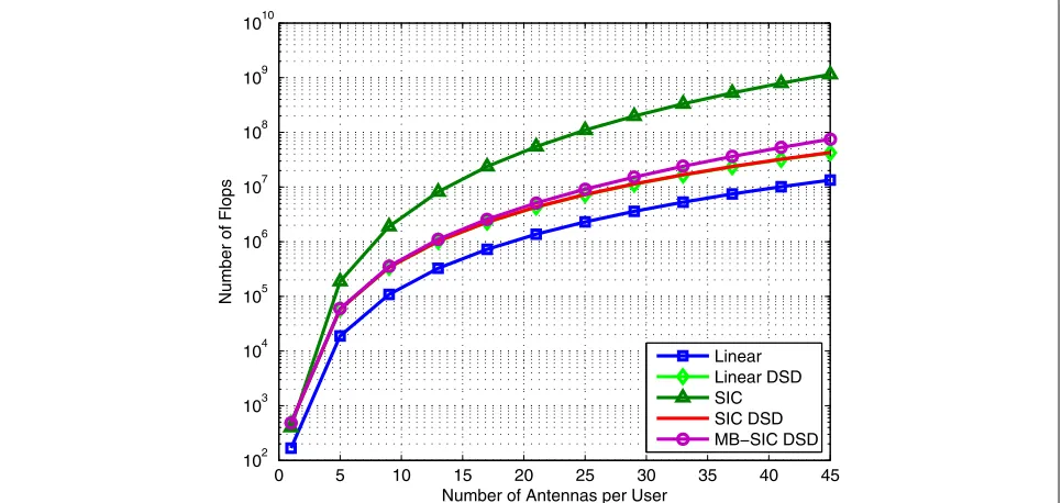
In Figs. 6 and 7, we plot the required number of FLOPs versus the number of active users and versus the number
0 5 10 15 20 25 30 35 40 45 102
103 104 105 106 107 108 109 1010
Number of Antennas per User
Number of Flops
Linear Linear DSD SIC SIC DSD MB−SIC DSD
Fig. 7Computational complexity versus number of antennas per user,K=10 active user,N=10 classes of users,Nt=KNtk,ntransmit antennas
of antennas per user, respectively. For Fig. 6 we consider N = 5 classes of users,Ntk,n = 2 transmit antennas per
user andNr=3KNtk,nreceive antennas. The MB-SIC and
SIC detectors with DSD have a lower computational cost than the coupled SIC detector. For this 5G context, with a high number of antennas, efficient coupled detectors are not feasible to be implemented; however, if a specific user class requires the benefits of complex detectors, the DSD algorithm reduces the cost so that more complex detec-tors could be applied as illustrated with MB-SIC in Fig. 6. For the results in Fig. 7, we consider that we haveK=10 active users and that we need to detect each user indepen-dently, i.e.,N=10. The number of transmit antennas per userNtk,n is increased. We also consider that the number
of receive antennas distributed around the cell is given by Nr = 2KNtk,n. The MB-SIC and SIC detectors with DSD
have a significantly lower complexity when compared with the SIC detector where all users are coupled.
It is worth noting that the curves displayed in Figs. 5, 6, and 7 will have a substantial decrease if the channel does not change over a time period due to quasi static channels. In this case, the equivalent channel matrices for each user class are stored for subsequent use. It would increase the gap, in terms of the computational cost, for the detection schemes using the DSD algorithm.
5.3 BER performance
In this subsection, the BER performance of the pro-posed algorithm is evaluated using different detectors which includes linear, SIC, and MB-SIC with linear MMSE receive filters. The SIC detector of [8] uses a norm-based cancellation ordering, the MB-SIC of [10] employs
a fixed number of branches, equal to the total number of transmit antennas per user classNtnfor the DSD schemes,
and norm-based ordering in its first branch. A massive MIMO system operating in heterogeneous networks with K active users is considered. We also consider the DAS configuration where theNr =NB+DQreceive antennas are distributed around the cell inDradio heads withQ antennas each and the remainingNBantennas are located at the BS. We consider QPSK modulation. The SNR per transmitted information bit is defined as
SNR=10 log10Ntσ 2 s Mσ2
n
, (37)
whereσs2is the common variance of the transmitted sym-bols, σn2 is the noise variance at the receiver and M is the number of transmitted bits per symbol. The numeri-cal results correspond to an average of 3000 simulations runs, with 500Nt symbols transmitted per run. For the
NB antennas at the BS, we employLk = 0.3, τ = 2,
the distance to the users is obtained from a uniform dis-crete random variable distributed between 0.4 and 0.7, the shadowing spread isσk = 1 dB and the transmit and receive correlation coefficients are equal toρrx=0.4. For theRremote arrays of antennas, we useLk,jtaken from a uniform random variable distributed between 0.3 and 0.5, the shadowing spreadσk,j=1 dB and the receive correla-tion coefficients are equal toρrx=0.5. When the number of transmit antennas at the users isNtk,n >1, the transmit
correlation coefficient is equal toρtx=0.55.
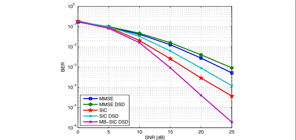
For the experiment in Fig. 8, we considerK = 12 user devices, where each user is equipped withNtk,n=3
trans-mit antennas and N = 3 classes of users. The system
0 5 10 15 20 25
10−6 10−5 10−4 10−3 10−2 10−1 100
SNR [dB]
BER
MMSE MMSE DSD SIC SIC DSD MB−SIC DSD
0 2 4 6 8 10 12 10−8
10−7 10−6 10−5 10−4 10−3 10−2 10−1 100
SNR [dB]
BER
MMSE MMSE DSD SIC SIC DSD MB−SIC DSD
Fig. 9BER versus SNR withK=8 active users,Ntk,n=8 transmit antennas per user,N=8 classes of users, andNr=128 receive antennas
employs perfect channel state information and QPSK modulation. For the DAS configuration, we considerNB= 8 receive antennas at the BS,D = 4 remote radio heads,
andQ = 7 receive antennas per remote radio head. We
can see from the figure that the decoupled SIC detec-tion presents a performance close to the coupled SIC detector with a difference around 2 dB in the high SNR region. In addition the decoupled SIC detector has a
drastic reduction in the computational cost when com-pared with its coupled version. The result also indicates a remarkable superiority in the performance for the MB-SIC receiver with the DSD scheme over the coupled MB-SIC detector which also has a lower computational complexity than the coupled SIC detector.
In the next example, we evaluate the performance of
the proposed scheme considering K = 8 active users,
0 2 4 6 8 10 12
10−5 10−4 10−3 10−2 10−1 100
SNR [dB]
BER
MMSE DSD with D=8 MMSE DSD with D=6 SIC DSD with D=8 SIC DSD with D=6 MB−SIC DSD with D=8 MB−SIC DSD with D=6
Fig. 10BER versus SNR withK=64 active users,Ntk,n=1 transmit antenna per user,N=4 classes of users,NB=34,Dremote antennas arrays with
each user transmitting withNtk,n = 8 antennas. We also
consider that we need to detect each user independently of each other, i.e.,N=8 classes of users with|Cn|=1 user per class. For the DAS configuration, we considerNB=64
receive antennas at the BS, D = 8 remote radio heads,
andQ = 8 receive antennas per remote radio head. The
Fig. 9 indicates that the performance of the SIC detector with DSD is close to the SIC detector with a lower com-putational complexity. Note that the results for MB-SIC with DSD show a very good performance with a com-putational complexity much lower than the SIC detector without DSD.
In Fig. 10 we evaluate the performance of the proposed scheme with MMSE, SIC, and MB-SIC detection. We
consider K = 64 active users,N = 4 classes of users,
|Cn|=16 users per class, andNtk,n =1 transmit antenna
per user. For the DAS configuration, we considerNB=34
receive antennas at the BS and Q = 7 receive
anten-nas per remote radio head. To show the behavior of the BER performance with different numbers of distributed antennas, we consider two configurations of remote radios heads,D= 8 andD= 6. As expected, the results shows that when the number of RRHs is increased, the BER per-formance is improved due to the low propagation effects caused by the short distances between users and some remote antenna arrays. We also can see from the figure that the SIC and the MB-SIC detector with DSD offer an excellent BER performance with a low computational cost.
6 Conclusions
In this paper, a mathematical signal model and the DSD algorithm for the uplink of massive MIMO systems oper-ating in heterogeneous cellular networks with different classes of users using CAS and DAS configurations have been presented. The proposed algorithm allows one to separate the received signals for each category of users efficiently into independent parallel single user class sig-nals at the receiver side, applying a common channel inversion and QR decomposition and assuming that the channel matrix was previously estimated. With the pro-posed scheme, it is possible to handle different classes of users in heterogeneous networks and to use differ-ent modulation and/or detection schemes for each class according to its data service requirements. The main advantage of DSD is the reduction in the computational cost of efficient detection schemes that, for its high computational complexity, are not feasible for implemen-tation when the signals received from all active users are coupled.
Appendix 1
Let us consider that a linear detector according to (21) is applied to the equivalent received signal vector (18) to detect the transmitted symbol vector of thenth user class
as in (33). If we define the matrixA¯n = WnHˇn and the vectorn¯n=Wnnnwe can rewrite (33) as
˜
yn= ¯Ansn+ ¯nn, (38)
then, in analogy with the analysis in Section 4, the sum rate for thenth user class after the detection is given by
Rn=
Kn¯nhas an inverse, we finally obtain
¯
Note that (41) and (31) will yield the same result which proves that the sum rate for the DSD algorithm is inde-pendent of the linear detection procedure.
Acknowledgements
This work was supported in part by grants of CNPq, FAPERJ, and DAAD.
Competing interests
The authors declare that they have no competing interests.
Publisher’s Note
Springer Nature remains neutral with regard to jurisdictional claims in published maps and institutional affiliations.
Author details
1Center for Studies in Telecommunications (CETUC), Pontifical Catholic
University of Rio de Janeiro (PUC-Rio), Rio de Janeiro, Brazil.2Communications
Research Laboratory, Ilmenau University of Technology, Ilmenau, Germany.
Received: 8 October 2016 Accepted: 8 July 2017
References
1. TL Marzetta, Noncooperative cellular wireless with unlimited numbers of base station antennas. IEEE Trans. Wireless Commun.9(11), 3590–3600 (2010) 2. EG Larsson, O Edfors, F Tufvesson, TL Marzetta, Massive MIMO for next
generation wireless systems. IEEE Commun. Mag.52(2), 186–195 (2014) 3. F Rusek, D Persson, B Lau, E Larsson, T Marzetta, O Edfors, F Tufvesson,
Scaling up MIMO: Opportunities, and challenges with very large arrays. IEEE Signal Process. Mag.30(1), 40–60 (2013)
4. RC de Lamare, Massive MIMO systems: Signal processing challenges and future trends. URSI Radio Science Bulletin (2013)
5. T Marzetta, Noncooperative cellular wireless with unlimited numbers of base station antennas. IEEE Trans. Wireless Commun.9(11), 3590–3600 (2010) 6. EG Larsson, F Tufvesson, O Edfors, TL Marzetta, Massive MIMO for next
generation wireless systems. IEEE Commun. Mag.52(2), 186–195 (2014) 7. 3GPP-LTE, Technical specification group radio access network: evolved
8. GD Golden, CJ Foschini, RA Valenzuela, PW Wolniansky, Detection algorithm and initial laboratory results using V-BLAST space-time communication architecture. Electron. Lett.35(1), 14–16 (1999). doi:10.1049/el:19990058
9. RC de Lamare, R Sampaio-Neto, Minimum mean-squared error iterative successive parallel arbitrated decision feedback detectors for DS-CDMA systems. IEEE Trans. Commun.56(5), 778–789 (2008)
10. RC de Lamare, Adaptive and iterative multi-branch MMSE decision feedback detection algorithms for multi-antenna systems. IEEE Trans. Wirel. Commun.12(10), 5294–5308 (2013).
doi:10.1109/TWC.2013.092013.130233
11. P Li, RC de Lamare, R Fa, Multiple feedback successive interference cancellation detection for multiuser MIMO systems. IEEE Trans. Wirel. Commun.10(8), 2434–2439 (2011)
12. P Demestichas, A Georgakopoulos, D Karvounas, K Tsagkaris, V Stavroulaki, J Lu, C Xiong, J Yao, 5G on the horizon: Key challenges for the radio-access network. IEEE Veh. Technol. Mag.8(3), 47–53 (2013) 13. H Pervaiz, L Musavian, Q Ni, in2015 IEEE International Conference on
Communication Workshop (ICCW). Area energy and area spectrum efficiency trade-off in 5G heterogeneous networks, (2015), pp. 1178–1183 14. W Roh, A Paulraj, MIMO channel capacity for the distributed antenna
systems. IEEE Veh. Technol. Conf.3, 1520–1524 (2002)
15. D Wang, J Wang, X You, Y Wang, M Chen, X Hou, Spectral efficiency of distributed MIMO systems. IEEE J. Selected Areas Commun.31(10), 2112–2127 (2002)
16. F Römer, M Fuchs, M Haardt. Distributed MIMO systems with spatial reuse for highspeed indoor mobile radio access. 20th Meeting of the Wireless World Research Forum (WWRF), Ottawa, Canada, (2008)
17. J Andrews, S Buzzi, W Choi, S Hanly, A Lozano, A Soong, J Zhang, What will 5g be? IEEE J. Selected Areas Commun.32(6), 1065–1082 (2014) 18. J Kermoal, L Schumacher, K Perdersen, et al, A stochastic MIMO radio
channel model with experimental validation. IEEE J. Selected Areas Commun.20(6), 1211–1226 (2002)
19. QH Spencer, AL Swindlehurst, M Haardt, Zero-forcing methods for downlink spatial multiplexing in multiuser MIMO channels. IEEE Trans. Signal Process.52(2), 461–471 (2004)
20. LU Choi, RD Murch, A transmit preprocessing technique for multiuser MIMO systems using a decomposition approach. IEEE Trans. Wireless Commun.3(1), 20–24 (2004)
21. V Stankovic, M Haardt, Generalized design of multi-user MIMO precoding matrices. IEEE Trans. Wireless Commun.7(3), 953–961 (2008)
22. CB Chae, S Shim, RW Heath, Block diagonalized vector perturbation for multiuser MIMO systems. IEEE Trans. Wireless Commun.7(11), 4051–4057 (2008)
23. L Arévalo, RC de Lamare, M Haardt, R Sampaio-Neto, in2015 IEEE International Workshop on Computational Advances in Multi-Sensor Adaptive Processing (CAMSAP). Uplink block diagonalization for massive MIMO-OFDM systems with distributed antennas, (2015)
24. V Stankovic, M Haardt. Improved diversity on the uplink of multi-user MIMO systems. 2005 European Conference on Wireless Technology (EuWiT), (2005), pp. 113–116
25. K Zu, RC de Lamare, M Haardt, Generalized design of low-complexity block diagonalization type precoding algorithms for multiuser MIMO systems. IEEE Trans. Commun.61(10), 4232–4242 (2013)
26. H Sung, S Lee, I Lee, Generalized channel inversion methods for multiuser MIMO systems. IEEE Trans. Commun.57(11), 3489–3499 (2009) 27. L Arévalo, RC de Lamare, K Zu, R Sampaio-Neto. Multi-branch lattice
reduction successive interference cancellation detection for multiuser MIMO systems. IEEE International Symposium on Wireless
Communications Systems, (2014), pp. 219–223
28. A Paulraj, R Nabar, D Gore,Introduction to space-time wireless communications. (Cambridge University Press, 2003)
29. CK Wen, S Jin, KK Wong, On the Sum-Rate of Multiuser MIMO Uplink Channels with Jointly-Correlated Rician Fading. IEEE Trans. Commun.
59(10), 2883–2895 (2011)
30. DNC Tse, P Viswanath,Fundamentals of wireless communications. (Cambridge University Press, 2005)
31. HQ Ngo, EG Larsson, TL Marzetta, Energy and spectral efficiency of very large multiuser MIMO systems. IEEE Trans. Commun.61(4), 1436–1449 (2013)
32. G Golub, CV Loan,Matrix computations. (The Johns Hopkins University Press, 1996)