Volume 2009, Article ID 854087,12pages doi:10.1155/2009/854087
Research Article
Biologically Inspired Intercellular Slot Synchronization
Alexander Tyrrell
1, 2and Gunther Auer
11DOCOMO Euro-Labs, 80687 Munich, Germany
2Institute of Networked and Embedded Systems, University of Klagenfurt, 9020 Klagenfurt, Austria
Correspondence should be addressed to Alexander Tyrrell,[email protected]
Received 30 June 2008; Revised 3 November 2008; Accepted 21 January 2009
Recommended by Erchin Serpedin
The present article develops a decentralized interbase station slot synchronization algorithm suitable for cellular mobile communication systems. The proposed cellular firefly synchronization (CelFSync) algorithm is derived from the theory of pulse-coupled oscillators, common to describe synchronization phenomena in biological systems, such as the spontaneous synchronization of fireflies. In order to maintain synchronization among base stations (BSs), even when there is no direct link between adjacent BSs, some selected user terminals (UTs) participate in the network synchronization process. Synchronization emerges by exchanging two distinct synchronization words, one transmitted by BSs and the other by active UTs, without any a priori assumption on the initial timing misalignments of BSs and UTs. In large-scale networks with inter-BS site distances up to a few kilometers, propagation delays severely affect the attainable timing accuracy of CelFSync. We show that by an appropriate combination of CelFSync with the timing advance procedure, which aligns uplink transmission of UTs to arrive simultaneously at the BS, a timing accuracy within a fraction of the inter-BS propagation delay is retained.
Copyright © 2009 A. Tyrrell and G. Auer. This is an open access article distributed under the Creative Commons Attribution License, which permits unrestricted use, distribution, and reproduction in any medium, provided the original work is properly cited.
1. Introduction
Slot synchronization is an enabling component for cellular systems. It is a prerequisite for advanced intercellular coop-eration schemes, such as interference suppression between neighboring cells, as well as multicast and broadcasting services. The problem of intercell slot synchronization is to align the internal timing references of all nodes, so that base stations (BSs) and user terminals (UTs) agree on a common reference instant that marks the start of a transmission slot. In the context of cellular systems a slot is composed of a number of successive uplink and downlink frames, referred to as superframe.
Network synchronization in cellular systems is com-monly performed in a master-slave manner: BSs synchronize to an external timing reference, known as the primary reference clock, and transfer this timing to UTs. This refer-ence clock can be acquired through the global positioning system (GPS) or through the backbone connection. The first method requires the installation of a GPS receiver at each BS, which increases costs and, more importantly, does not work in environments where GPS signals cannot be received.
For high accuracy, the second method requires precise delay compensation, and the accuracy severely decreases when clocks are chained [1].
1
0
T τj 2T
t
φi(t) Fire Fire
(a) (b)
Δφ(φi(τj))
Figure1: (a) Uncoupled phase function and (b) phase increment upon reception of a pulse.
framework for the convergence to synchrony. Various aspects regarding the application of the PCO model to wireless networks are addressed in literature: radio effects such as propagation delays [7], channel attenuation, and noise [8,9], and allowing for long synchronization words [10]. The rules that govern the PCO synchronization model are intriguingly simple and serve as a basis for inter-BS synchronization.
The proposed cellular firefly synchronization (CelFSync) algorithm adapts the PCO model to account for constraints of cellular networks. CelFSync operates over-the-air, in a decentralized manner; no constraints are imposed on the availability of an external timing reference. As BSs and UTs typically transmit on successive downlink and uplink frames, two groups need to be distinguished; the BS group transmitting on the downlink and the UT group transmitting on the uplink. To facilitate the formation of two groups, two synchronization words are specified, one associated to BSs and the other to UTs. UTs transmit an uplink sync word based on their internal timing reference, which is received by BSs to update their own timing; in return UTs adjust their timing reference upon reception of downlink sync words from neighboring BSs. Thus, unlike [2], no separate frequency band is required as sync words are transmitted in-band with data. Moreover direct communication among BSs is not mandatory as synchronization is performed by hopping over UTs. As the downlink sync word is mandatory for conventional cellular systems to align the timing of UTs with the BS, the only overhead for inter-BS synchronization is the insertion of the uplink sync word. Thanks to the proposed strategy, the network is able to synchronize starting from an arbitrary misalignment, and propagation delays only affect the achieved accuracy but do not compromise the convergence to synchrony.
When considering a scenario where BSs are separated by several hundred meters up to a few kilometers, propagation delays severely affect the attainable timing accuracy. We propose to combine CelFSync with the timing advance procedure, which ensures that UT uplink transmissions arrive simultaneously at the BS. Compensating intracell propagation delays with the timing advance procedure, as well as selecting cell edge users to participate in CelFSync, are effective means to substantially improve the achieved interbase station timing accuracy.
The remainder of the paper is structured as follows. In
Section 2the PCO model and its achieved synchronization
accuracy in the presence of delays are presented. InSection 3
CelFSync is developed by adopting the rules that govern the synchronization of PCOs to cellular networks, andSection 4
combines CelFSync with timing advance to compensate the effects of propagation delays. Practical constraints regarding the implementation in cellular networks are addressed in
Section 5, and simulation results are presented inSection 6
that investigate the time to convergence and the achieved accuracy for an indoor office environment as well as an urban macrocell deployment composed of hexagonal cells.
2. Synchronization of Pulse-Coupled Oscillators
Pulse-coupled oscillators (PCOs) describe systems where individual nodes periodically emit pulses and adjust their internal time reference upon reception of pulses from neighboring oscillators. In this section the rules that govern the PCO model [6] are summarized, and the achieved accuracy in the stable state is elaborated.
2.1. Phase Function. A PCO is described by its phase function φi(t), 1≤i≤N, whereNis the number of oscillators. This function evolves linearly over time with natural periodT:
dφi(t) dt =
1
T. (1)
Wheneverφi(t)= 1 at reference instantt =τi, the PCO is said tofire, it transmits a pulse and resets its phase to 0. Then φi(t) increases again linearly, and so on.Figure 1(a) plots the evolution of the phase function (1) during one period with initial conditionφi(0) =0. The phase function can be seen as an internal counter that dictates the emission of pulses. In the following, we consider that all nodes have the same dynamics, that is, clock jitter is considered negligible.
2.2. Synchronization Rules. The goal of slot synchronization is to align the internal time references of all nodes, so that all PCOs fire simultaneously. To do so, the phase φi(t) is adjusted when a pulse is received. When coupled to others, an oscillatoriis receptive to the pulses of its neighbors and adjusts its phaseφi(t). When node j fires at instantτj, the phase of nodeiinstantly increases by a valueΔφthat depends on its current valueφi(τj):
φi
τj
−→φi
τj
+Δφφi
τj
. (2)
The phase incrementΔφis determined by the phase response curve, which in [6] was chosen to be a linear function:
φ+Δφ(φ)=min(αφ+β, 1), (3)
where the coupling parameters α and β determine the coupling between oscillators. Figure 1(b) plots the time evolution of the phase when receiving a pulse att=τj. The received pulse causes the oscillator to fire early.
0 0.2 0.4 0.6 0.8 1
Phases
φi
0 1 2 3 4 5 6 7
t/T
Figure2: Phase representation of the synchronization ofN =30 PCOs.
2.3. Convergence. An example of the synchronization of pulse-coupled oscillators is shown in Figure 2. Initially all nodes start with a random phase, which increments according to (1) until one phase reaches the threshold. At this instant and each time a phase reaches 1, neighboring nodes increment their phase according to (3). Over time, order emerges from a seemingly chaotic situation where nodes fire randomly, and inFigure 2, all nodes fire in synchrony within five periods.
A key feature in the synchronization of PCOs is that, over time, nodes cluster into groups of oscillators. This phenomenon is referred to asabsorptionand occurs when a pulse forces nodes to exceed their firing threshold, causing them to fire immediately. The absorption limitφis derived from (3):
φ= 1−β
α . (4)
As nodes have the same internal dynamics and if they are coupled all-to-all, absorptions remain permanently (see
Figure 2). Therefore nodes following the PCO rules first gather into groups that gradually absorb one another, and after some time, always coalesce into one synchronized group.
In [11] Lucarelli and Wang extended the demonstration of [6] to remove the all-to-all assumption. Under weak coupling assumptions, that is,αclose to 1 andβclose to 0 in (3) (no proof for strong coupling exists), equivalent phase deviation variables are derived for each node (each variable represents the mean local interactions over one period) and are shown to asymptotically converge to the same value [11]. Unfortunately the analysis in [11] is not applicable when delays are introduced. Izhikevich showed that there is no equivalent phase deviation variable when interactions are delayed [12]. As the proposed inter-BS synchronization scheme always delays interactions (see Section 3), an ana-lytical convergence study appears infeasible. Convergence is consequently studied through simulations inSection 6.
2.4. Impact of Delays. When delays are introduced, such as propagation delays, the coupling between two nodesiand j is delayed byνi j. In the presence of coupling delays a network of PCOs may become unstable, and the network is unable to synchronize [13]. Stability is regained by introducing a refractory period of durationTrefr after reference instantτi
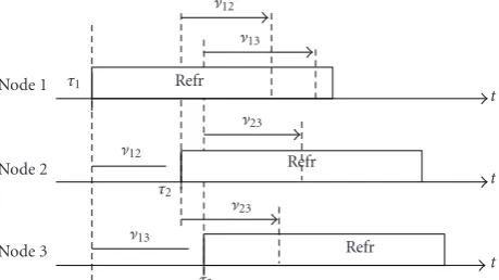
ν12 ν13
Node 1 τ1 Refr
t
Node 2 ν
12
ν23
Refr
t
Node 3 ν13
ν23
Refr
t τ2
τ3
Figure3: Synchronization of three pulse-coupled oscillators with delays.
[7]. In refractory, whenφi(t)< φrefrwithφrefr =Trefr/T, no
phase increment is possible, so that received pulses are not acknowledged. The duration of the refractory period needs to be at least twice the maximum delay between two nodes, so thatechosare not acknowledged [7]:
Trefr>max
i,j 2νi j. (5)
Because of delays nodes are no longer able to perfectly align their reference instantsτi [7]. Nevertheless nodes converge to a stable state where reference instants are spread within an interval limited only by the coupling delaysνi j, as detailed for networks of two and three nodes in the remainder of this section. Further discussion on the achieved accuracy of the PCO scheme in the presence of delays is available in [14].
2.4.1. Two Nodes. The accuracy limits for a network ofN=2 nodes is bounded by the interval of reference instants leading to a stable state [7]. Suppose that the reference instants of two nodesiandjare aligned such thatτj> τi+νi j; then nodeiis theforcing nodethat imposes itsdelayedreference onto node j. After coupling, node j is pulled to the delayed timing of nodei, τj = τi+νi j (as shown for nodesi =1 and j =2 inFigure 3), as long as the pulse of nodeifalls within the absorption interval (4) of nodej, that is,φj(τi+νi j)∈[φ, 1]. Ifτi> τj+νi j, the roles are reversed, in the way that node j imposes its delayed timing onto nodei, so that after coupling τi =τj+νi j. On the other hand, if the reference instant of nodeiis within the range
τi∈
τj−νi j,τj+νi j
, (6)
the pulses from node j fall into the refractory period of node i, and vice versa, and are thus not acknowledged. This corresponds to the stable state where the phases of both nodes are not adjusted. According to (6) the achieved accuracy is bounded by the propagation delayνi jand is given by [7]:
i jτi−τj ≤ νi j. (7)
in a similar way to a master-slave synchronization scheme. However, the achieved state is random: it depends on the initial condition and on interactions with other nodes in the network. Therefore the role of the forcing node is arbitrary, and PCO synchronization is still considered decentralized.
2.4.2. Three Nodes. The analysis of [7] is extended to a network of N = 3 nodes in the following. Two cases are distinguished.
(i) The forcing node is directly connected with all nodes.
(ii) The forcing node is the edge node of a line topology and imposes its timing to the other edge node by hopping over the center node.
Considering (i), suppose that node 1 is the forcing node that imposes its delayed timing onto nodes 2 and 3. This state is shown inFigure 3: node 1 fires at instantt = τ1, which
causes nodes 2 and 3 to increment their phases at instants τ1+ν12andτ1+ν13, respectively. Assuming that their phase
exceeds the absorption limit (4), nodes 2 and 3 fire at instants τ2 = τ1 +ν12 andτ3 = τ1+ν13, and subsequently enter
refractory. No further phase increments occur because the pulses from nodes 2 and 3 are received when nodes are in refractory (5). Therefore the network is in a stable state, and the achieved accuracies of node 1 relative to node 2 and 3 amount to12=ν12and13=ν13, respectively. Interestingly,
the accuracy between nodes 2 and 3 is equal to the difference in delays with forcing node 1, that is,13= |ν12−ν13|. Thus
this achieved accuracy does not depend on the direct delay ν23but on the delay difference with the forcing node 1.
In case (ii) the considered nodes form a line topology, where the edge nodes 1 and 3, cannot communicate directly. Suppose that node 1 is the forcing node that imposes its timing onto node 3 via the center node 2. As the accuracy between adjacent nodes is bounded by (7), that is,12 ≤ν12
and23 ≤ν23, the resulting accuracy interval over two hops
between edge nodes 1 and 3 amounts to the sum of delays: 13≤ν12+ν23.
3. Decentralized Intercell Synchronization
This section presents an adaptation of the PCO model to per-form intercell synchronization. To facilitate reliable exchange of reference instants in the presence of signal fading, interference, and noise, long synchronization sequences that are transmitted in-band with data are considered instead of pulses. Furthermore, half-duplex transmission is considered, which implies that nodes cannot receive whilst transmitting. To this end, when two nodes transmit sync words that partially overlap, both nodes are unable to detect the sync word sent by the other node, referred to asdeafnessbetween nodes. Hence both nodes are effectively uncoupled, an effect which may severely disrupt intercell synchronization. Further accounting for constraints in cellular systems, the frame structure does not allow for overlapping downlink and uplink slots. Thus synchronized BSs and UTs should not transmit simultaneously.
T
τ1
τ2
τ1
τ2
T/2
τ1
τ2
Δ
In
-p
h
as
e
sync
hr
onization
An
ti
-p
h
as
e
sync
hr
onization
Out-of-phase
sync
hr
onization
t
t
t
t
t
t
Figure4: Synchronization regimes of pulse-coupled oscillators.
The proposed cellular firefly synchronization (CelFSync) scheme takes into account these fundamental constraints, by resorting to an out-of-phase synchronization regime, intro-duced inSection 3.1. CelFSync relies on two synchronization sequences, one transmitted by BSs to adjust timing references of UTs, and a second one transmitted by UTs to adjust timing references of BSs, based on rules that are established inSection 3.2. The detection of the two distinct synchroniza-tion sequences in an asynchronous environment is discussed in Section 3.3. For ease of explanation, propagation delays are neglected in this section and are treated specifically in
Section 4.
3.1. Synchronization Regimes. A system of PCOs is said to be synchronized when all nodes have reached a stable state where their internal timing references are aligned, constrained to the considered synchronization regime [15]. The synchronization regime is characterized by the phase difference Δ = τ1−τ2 between two synchronized groups
in the stable state, where members of the same group are perfectly aligned. Depending on the phase difference Δ, three synchronization regimes are distinguished [15], as illustrated in Figure 4. If there is no phase shift, Δ =
0, the regime is said to be in-phase. If the phase shift is exactly equal to half a period, Δ = T/2, nodes have reached anantiphasesynchronization regime. Finally if the phase difference between oscillators is Δ=/0 and Δ=/T/2 between the first and second groups (andT −Δbetween the second and first groups), then oscillators areout-of-phase synchronized.
The in-phase regime is the most common form of synchronization; pacemaker cells pulse simultaneously to pump the heart, fireflies emit light at the same time. Antiphase synchronization is also familiar; when walking, our legs are antiphase synchronized: the left foot touches the ground half a period after the right one, and vice versa.
BSa νai UTi
Cell boundary
νbi
BSb
Figure5: Cellular network topology with two BSs and one UT.
T
Figure6: Synchronization principle of CelFSync.
synchronization ensures that uplink and downlink transmis-sions in the steady state do not overlap, so that detrimental effects of deafness between nodes, inherent to half-duplex transmission, are mitigated.
3.2. Cellular Firefly Synchronization. The goal of CelFSync is to synchronize in time the transmission slots of a cellular network, so that neighboring BSs mutually align the start of the superframe preamble. The timing information between BSs is conveyed by implicitly hopping over mobiles close to the cell edge, as exemplified inFigure 5. Hopping on the UT enables to extend the reception range of sync words, and thus allows for robust intercell synchronization, even when neighboring base stations do not hear one another.
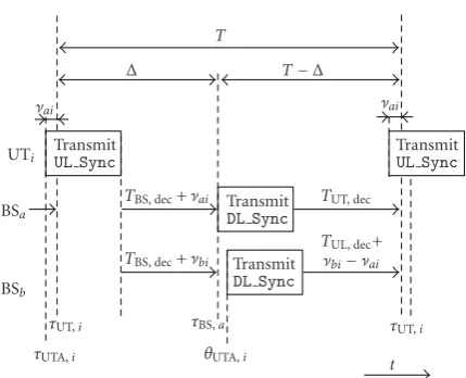
CelFSync adapts the PCO synchronization model to establish an out-of-phase synchronization regime. The desired stable state is illustrated for one user terminal UTi and one base station BSainFigure 6. Unlike the PCO model, instead of pulses, nodes transmit long synchronization sequences denoted by UL Sync and DL Sync of duration
TUL,Sync andTDL,Sync, respectively. For slot synchronization
three states are distinguished: transmission of the sync word, the refractory period, and the listen state. Transmission starts when a node fires (see τUT,i for UTi in Figure 6). Half-duplex transmission is considered: when a node transmits, its receiver is switched off. After transmission of the sync word nodes enter the refractory period, where detected sync words are not acknowledged. In listen state nodes maintain a phase function, that is, adjusted upon detection of a sync word. Key to separating nodes into two predefined groups is achieved by three types of interactions as follows.
UT-BS Coupling. Base station BSa estimates the reference instant of UTi by detecting its sync word UL Sync; the estimate of this reference instant is denoted byτUT,i. In order
to establish the desired out-of-phase synchronization regime, BSa adjusts its phase functionφBS,a exactlyΔseconds after UTi has fired, at instantθUT,i = τUT,i+Δ. If the coupling instantθUT,ifalls within the listen state of BSa, the receiving BS increments its phase:
The phase response curveΔφBS is chosen according to (3),
such that phase increments are strictly positive:
φ+ΔφBS(φ)=min
αBSφ+βBS, 1
. (9)
The coupling parameters are chosen in accordance to the PCO synchronization model:αBS>1 and 0< βBS<1.
The BS decoding delay TBS,dec, shown in Figure 6,
specifies the interaction delay between the instantUL Sync detected atτUT,i+TUL,Syncand the coupling instantθUT,i =
τUT,i+Δ. It is an important parameter for two reasons. Firstly
TBS,decallows for a processing delay at the receiver in order
to perform link level synchronization. SecondlyTBS,decneeds
to be appropriately chosen, so that the desired out-of-phase synchronization regime is reached. As BSs fireΔafter UTs, the BS decoding delay yields
TBS,dec=Δ−TUL,Sync. (10)
BS-UT Coupling. The considered user terminal UTi esti-matesτBS,a, the reference instant of BSa. If the reception of
DL Syncfrom BSaat instantθBS,a=τBS,a+T−Δfalls within
the listen state of UTi, the receiving UT increments its phase:
φUT,i
Again the phase response curve for BS-UT couplingΔφUTis
chosen according to (3):
φ+ΔφUT(φ)=min
UT decoding delay that enforces UTs to fireT−Δafter BSs is equal to (seeFigure 6):
TUT,dec=T−Δ−TDL,Sync. (13)
Thanks to this strategy, the formation of two groups is controlled. Starting from an arbitrary initial misalignment, where all reference instants τUT,i, τBS,a are randomly dis-tributed within [0,T], by following simple coupling rules, reference instants of UTs and BSs separate over time into two groups; all BS fire Δ after UTs, and all UTs fire T −
Δ after BSs. This state corresponds to the synchronized state shown in Figure 6. Convergence is verified through simulations in Section 6; by appropriately selecting the coupling parameters, it is shown that synchronization is always accomplished.
BS-BS and UT-UT Coupling. In case BSs can communicate directly or UTs are placed close to one another, convergence may be accelerated by allowing coupling between nodes of the same group. Moreover, the occurrence of deafness between nodes decreases because the number of nodes that are potentially coupled is increased. As half-duplex transmission is considered, BS-BS and UT-UT couplings are useful only during the coarse synchronization phase, that is, among nodes whose reference instants are misaligned by more than the sync word length.
Phase adjustments are made similarly to (8) and (11) for BSs and UTs; however decoding delays are different, as nodes need to align in time with other nodes from their own group. Therefore the interaction delay upon detection
ofDL SyncandUL Syncneeds to be equal to one periodT,
giving a decoding delay ofTBS-BS,dec =T−TDL,Sync for BSs
andTUT-UT,dec=T−TUL,Syncfor UTs.
Active UT Selection. Since uplink sync words UL Sync should be heard by multiple BSs, it is reasonable to select a subset of UTs close to the cell boundary to participate in intercell synchronization. Therefore, in each cell, the base station selects the NUT UTs with the largest propagation
delay among NUT,tot total UTs in the cell. The remaining
NUT,tot−NUTUTs are not active in CelFSync and follow the
timing reference dictated by their closest BS, by aligning their local clocks based onDL Sync.
3.3. Synchronization Word Detection. CelFSync relies on the detection of transmitted DL Sync andUL Syncsequences. In the following, we assume that uplink and downlink sync words are two different random sequences, each composed of M symbols. Sync word detection is carried out by the link-level synchronization unit, which cross-correlates the received signal streamx(t) with the sync word s(t), where s(t) = sUL(t) if uplink sync words are to be detected,
and s(t) = sDL(t) otherwise. The output of the link-level
synchronization unitiis denoted byri(t)=
x(t−τ)s∗(τ)dτ. The correlator output produces a series of peaks, in a similar way to the emission of pulses in the PCO model, and detection of a sync word is declared whenri(t) exceeds the detection thresholdR[16].
Signal fading may attenuate the received signal x(t), which may result in a missed detection. The probability that reference instants τUT,i and τBS,a are correctly detected is defined as [17]
Pd=Pr
ri(t)≥R|H
, (14)
whereH is the hypothesis that a sync word is present at the receiver. On the other hand, as sync words are transmitted in-band, cross-correlation of s(t) with other sync words, payload data or noise produces spurious peaks, so that detection of a sync word may be declared although no sync word is present, giving rise to a false alarm. The false alarm probability is defined as [17]
Pfa=Pr
ri(t)≥R|H
, (15)
whereH, the hypothesis that no sync word is present at the receiver, is the complement ofH.
The Neyman-Pearson criterion is used to design the sync word detector [17]: the detection threshold R is set according to the desired false alarm ratePfa; onceRis set, the
detection ratePd is determined. The impact of false alarm
and detection rates on an adaptation of the PCO model to ad hoc networks was studied for a multicarrier system in [18]. It was shown that false alarms have a higher impact on the convergence than missed detections 1−Pd. Hence, it is
necessary to maintain a sufficiently low false alarm rate [18]. The reliability of the link-level synchronization unit can be enhanced by increasing the length of the sync wordM. IncreasingM improves the detection rate for a given false alarm rate, at the expense of higher overhead [18].
4. Compensation of Propagation Delays
The accuracy of CelFSync is limited by propagation delays, similarly to the PCO model discussed in Section 2. In an indoor environment where distances between nodes are typically small, propagation delays are negligible. However, for cellular systems where the inter-BS distance is up to a few kilometers, Section 4.1reveals that propagation delays cannot be ignored. A common procedure to align uplink transmissions is the timing advance procedure, described in
Section 4.2. Timing advance is combined with CelFSync in
Section 4.3to achieve a timing accuracy within a fraction of the inter-BS propagation delays.
4.1. Achieved Accuracy in the Stable State. After CelFSync converges and reaches a stable state, reference instants of BSs and UTs are out-of-phase synchronized (seeFigure 6), and no phase increments occur. In the following discussion a sufficient refractory period (5) is assumed; then stability is maintained and the achieved timing accuracy in the stable state between any two nodes is bounded by (7). In the presence of propagation delays, the stable state condition (6) in terms of the reference instants of BSaand UTitranslates to
τBS,a∈
τUT,i+Δ−νai,τUT,i+Δ+νai
, (16)
where νai is the propagation delay between BSa and UTi. When the upper bound in (16) is approached, thenτBS,a =
τUT,i + Δ+νai, UTi is the forcing node that imposes its timing onto BSa. Likewise, (16) approaches the lower bound,
τUT,i=T−Δ+τBS,a+νai, when BSais the forcing node that imposes its timing onto UTi.
bounded by the sum of the BSa to UTi and UTi to BSb propagation delays:
τBS,b−τBS,a≤νai+νbi. (17)
Given that in cellular networks the inter-BS distance is up to a few kilometers, propagation delays have a major impact on the achieved accuracy in the stable state.
4.2. Timing Advance Procedure. As UTs are arbitrarily dis-tributed within the cell, the distance dai between UTi to BSavaries. Since propagation delays are distance dependent through νai = dai/c, where c is the speed of light, the observed timing reference of BSa measured at different UTs, denoted τBS,a = τBS,a + νai, are mutually different. To ensure that uplink transmissions arrive simultaneously at their own base station, timing advance is a common procedure in current cellular systems [19] and in wired telecommunication systems [20]. For timing advance UTi advances its transmission by νai, the propagation delay to its serving BS, taken to be BSa (see Figure 5). The uplink reference instant of UTi including timing advance is given by
τUTA,i=τUT,i−νai. (18)
The propagation delayνai may be determined by esti-mating the round trip delay between BSa and UTi [21]. Upon reception ofDL Syncfrom BSa, UTiresponds with the transmission of a random access preamble (RAP) atτRAP,i=
τBS,a+TRAP. SinceTRAPis a constant known to BSa, the round trip delay 2νaiis determined by detecting the received timing of the RAP at BSa. In addition, the RAP identifies UTi, so that BSacan distribute the estimate ofνaito UTi.
4.3. CelFSync with Timing Advance. In order to combat propagation delays, we propose to combine CelFSync with the timing advance procedure. If UTiknows the propagation delay to its serving base station BSa, the corresponding round trip delay of 2νaican be compensated. Owing to the multi-point-to-point topology specific to cellular networks, BSaof cellAtypically serves several mobiles UTi,i∈A, each with a specific propagation delayνai. Hence, all timing inaccuracies, the propagation delays from BSato UTiand back from UTi to BSa, must be compensated for at the mobile UTi. This is accomplished by advancing both, the transmittedUL Sync andthe coupling of the receivedDL Syncat UTi, by the BS-UT propagation delayνai.
For the following discussion, suppose that UTi has carried out the timing advance procedure with BSa, but its
UL Synctransmission is received by BSb.
UT-BS Coupling. For CelFSync with timing advance, UTi sends the uplink sync word UL Sync at the advanced reference instant τUTA,i = τUT,i−νai in (18). Then a phase
UL Sync TransmitUL Sync TBS, dec+νai
Figure7: Combination of CelFSync with timing advance.
BS-UT Coupling. For BS-UT coupling (11), we propose to also advance the coupling by the propagation delay. So given that UTiis timing aligned to BSa, but receivesDL Syncfrom BSb, the mobile UTiadvances its coupling byνai. Then the receivedDL Syncfrom BSbleads to a phase increment at UTi at instantθBSA,b=θBS,b−νai, so that (11) changes to
Figure 7summarizes the proposed combination of CelF-Sync with timing advance: UTistarts transmision atτUTA,i=
τUT,i−νai, so that the coupling at BSaoccurs exactly atτBS,a=
τUT,i+Δ; in return, BSastarts transmission of its sync word, whose decoding time is reduced at UTibyνaiso that UTifires exactlyT−Δafter BSa. Hence, all entities within one cell are perfectly timing aligned, and thus, the only remaining source of timing inaccuracies is between entities of neighboring cells.
In the synchronized steady state, sync words observed at θUTA,i andθBSA,b must fall into the refractory period, such thatτBS,b ≤ θUTA,i < τBS,b+Trefr for UT-BS coupling, and
τUT,i≤θBSA,b < τUT,i+Trefrfor BS-UT coupling. The steady
state accuracy between BSb and UTiis bounded by the two extreme cases when either BSb or UTi is the forcing node. In case UTi is forcing, the observed timing at BSb yields
τBS,b =τUT,i+Δ+νbi−νai. Otherwise, if BSbis forcing, the timing imposed on UTiamounts toτUT,i=τBS,b−Δ+νbi−νai. This means that the achieved accuracy in the steady state between BSband UTiis bounded by
τBS,b∈
τUT,i+Δ−νbi−νai,τUT,i+Δ+νbi−νai. (21)
Therefore combining timing advance with CelFSync always achieves an accuracy, that is, bounded by thedifferenceof UT-BS propagation delays.
In order to analyze the achieved inter-BS accuracy, the case study depicted inFigure 5and discussed inSection 4.1
is revisited. Given that UTi is time aligned to BSa, that is,
is the link from UTi to BSb, so that the UT-BS accuracy bound (21) can be directly applied. Substituting τUT,i =
τBS,a−Δinto (21), the inter-BS accuracy between BSa and BSbover two hops is bounded to
τBS,b−τBS,a≤νai−νbi. (22)
Provided that UTi is located near the cell boundary, its propagation delays to BSa and BSb are similar, so that the difference |νai −νbi| is much smaller than the individual delaysνai andνbi. This is in sharp contrast to the achieved accuracy without timing advance in (17), which is bounded by the sum of propagation delays. Increasing the UT density per cellNUT,tot increases the probability of selected UTs to
be close to the cell edge, which has the appealing effect that the inter-BS accuracy (22) improves. The accuracy bound is extended to multiple UTs in the Appendix.
The working principle of CelFSync including timing advance is summarized as follows.
(i) UTi connects to the BS with the strongest received signal strength, assumed to be BSa.
(ii) UTialigns its timing to BSaby carrying out a timing advance procedure, as described inSection 4.2. (iii) If identified as active, UTiemitsUL Syncat reference
instantsτUTA,iin (18) and adjusts its phaseφUT,iupon reception ofDL Syncaccording to (20).
5. Implementation Aspects
In order to integrate CelFSync into a cellular mobile radio standard, several practical constraints need to be taken into consideration. Constraints regarding the frame structure and the chosen duplexing scheme are addressed in this section.
5.1. Frame Structure. CelFSync is implemented and verified based on the frame structure taken from the specifications of the Wireless World Initiative New Radio (WINNER, URL:
http://www.ist-winner.org.) system concept [22]. Consecu-tive downlink and uplink slots constitute one frame, and a number of successive frames form one super-frame of duration T. One uplink and one downlink sync words
UL SyncandDL Syncare placed into the superframe with
a relative spacing ofΔ, as illustrated inFigure 4.
The downlink sync wordDL Syncallows UTs to synchro-nize to its BS and is therefore essential for cellular networks. Unlike DL Sync, the insertion of the uplink sync word
UL Syncadds overhead, asUL Syncis typically not required
in current cellular networks. Fortunately, this overhead is modest asUL Syncis typically transmitted with low rate. For the WINNER system the respective durations for superframe
and UL Sync are 5.8 ms and 45μs. Hence the resulting
overhead is less than 1% [22].
5.2. Acquisition and Tracking Modes. An intrinsic property of PCO synchronization is that coupling between nodes effectively shortens period T. However, cellular systems typically rely on a fixed frame structure, which specifies the
way uplink and downlink slots are arranged to exchange payload data. To this end, whilst the reception of payload data is still ongoing, CelFSync may shorten the period of two successive reference instants toT≤T, which effectively shortens the duration of the superframe.
As long as the effective period T is only slightly shortened, such thatT−T ≤ ε, insertion of a guard time with duration TG > ε ensures that reception of payload
data is completed before a sync word is transmitted. The conditionT−T ≤ εcorresponds to thetracking modein the steady synchronization state, where small offsets due to clock skews, leading to deviations of the natural oscillation periodTbetween nodes, are compensated.
In case of coarse timing misalignments between cells, so thatT−T> ε, the network is inacquisition mode. Potential conflicts in acquisition mode are avoided by
(i) suspending payload data transmission while intercell synchronization is in progress;
(ii) shortening the superframe duration toTsf< T.
Scheme (i) does not allow for exchange of payload data before CelFSync has reached a steady state. Given that a steady state is likely to be maintained for hours or even days, while CelFSync typically converges within a fraction of a second or so, the loss in system throughput due to suspended data transmissions may be acceptable. For instance, scheme (i) is applied to facilitate the synchronization procedure in the wireless LAN standard 802.11 [23,24]: periodically, data transfer is preempted, and the access point transfers its clock value, known as timing synchronization function (TSF), to the networks participants.
Scheme (ii) avoids conflicts by forcing the effective period T to be at least as long as Tsf. By doing so, continuous
exchange of payload data is maintained, at the expense of reducing the throughput during acquisition by about (T−
Tsf)/T.
5.3. Duplexing Scheme. CelFSync is applicable to both time division duplex (TDD) and frequency division duplex (FDD). Nodes adjust their internal clocks based on received sync words; whether the uplink and downlink sync words are transmitted on different frequency bands or not is irrelevant. The discussion in this paper targets half-duplex transmission, where nodes cannot receive and transmit at the same time, applicable to TDD and half-duplex FDD. Full-duplex FDD benefits CelFSync, since nodes can transmit and receive simultaneously, which eliminates deafness due to missed sync words whilst transmitting.
the entire network in a completely decentralized manner. To avoid this difficulty, in [25] a scenario was considered where only a few nodes have access to a global time reference. The PCO model was extended such that these master nodes impose a global time reference to the entire network, even though the number of master nodes was only a small fraction of the total number of nodes in the network. Furthermore, the behavior of normal nodes that do not have access to a global time reference is not modified at all.
Applied to CelFSync a subset of BSs get access to a global time reference. These master BS emit downlink sync words DL Sync with a slightly shortened period Tma <
T, and are not receptive to sync words from other nodes [25]. Neighboring cells then align their reference instants following the synchronization rules outlined inSection 3.2. It was demonstrated in [25] that for 0.9T ≤ Tma < T,
arbitrarily large networks are reliably synchronized. By doing so the problem of synchronizing large networks with a distributed algorithm is reduced to synchronizing a number of cells (typically up to 2 or 3 tiers) around a master BS.
6. Performance Evaluation
To evaluate the performance of CelFSync two deployment scenarios are considered: first an indoor office scenario in
Section 6.1; and second a macrocell deployment modeled by an hexagonal cell structure inSection 6.2[26]. All nodes transmit with the same powerPt. The propagation channel
between nodesiand j is modeled as a distance-dependent pathloss channel. Node j receives the transmission of a node i at a distance di j with power Ptd−
χ
i j , where χ is the pathloss exponent. The signal-to-noise-plus-interference ratio (SINR) of a received sync word is composed of the received power of the sync word, divided by the level of interference plus thermal noise with powerN0. The detection
threshold is set for a given false alarm rate, which enables the computation of the detection probabilityPdfor each received
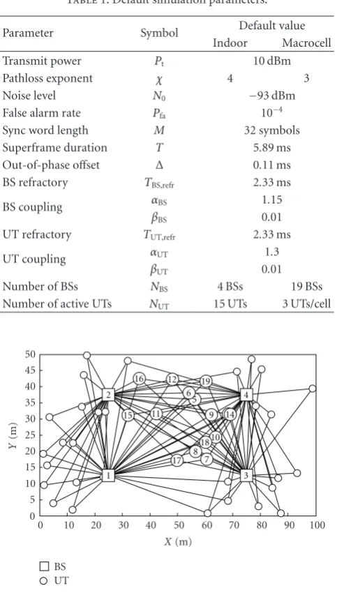
sync word as a function of the current SINR (seeSection 3.3). Unless otherwise stated, the parameters shown inTable 1are used in the simulations.
Both environments impose different strains on CelFSync. In the indoor environment, sync words are subject to a high level of interference from other transmitting UTs. In the outdoor environment, the large distance between UTs and BSs results in higher channel attenuations, creating a more sparsely connected network, which implies that network synchronization is to be carried out over multiple hops.
In both scenarios, Monte-Carlo simulations are con-ducted for 5000 sets of initial conditions: all BSs initially commence with uniformly distributed internal timing refer-ences, while UTs are locally synchronized to their closest BS. Synchronization is declared when two groups have formed, so that reference instants of UTs are aligned and out-of-phase synchronized with reference instants of BSs, with a relative timing difference ofΔ.
6.1. Indoor Office Environment. An indoor office with two corridors and ten offices on each side is considered. This
Table1: Default simulation parameters.
Parameter Symbol Default value
Indoor Macrocell
Transmit power Pt 10 dBm
Pathloss exponent χ 4 3
Noise level N0 −93 dBm
False alarm rate Pfa 10−4
Sync word length M 32 symbols
Superframe duration T 5.89 ms
Out-of-phase offset Δ 0.11 ms
BS refractory TBS,refr 2.33 ms
BS coupling αBS 1.15
βBS 0.01
UT refractory TUT,refr 2.33 ms
UT coupling αUT 1.3
βUT 0.01
Number of BSs NBS 4 BSs 19 BSs
Number of active UTs NUT 15 UTs 3 UTs/cell
1
Figure8: Considered indoor network topology.
setting was defined for the local area scenario in WINNER [27]. The network topology withNBS = 4 BSs andNUT =
15 UTs participating in CelFSync is depicted in Figure 8. The selected UTs (marked as bold circles) can communicate directly with all BSs (marked as squares). UTs that do not participate in the network synchronization procedure do not transmit UL Sync and adjust their slot oscillator based on receivedDL Sync.
Results plotted inFigure 9 elaborate on the time taken for the entire network to synchronize. The time to synchrony Tsync is normalized to the duration of a superframe T. Figure 9plots the cumulative distribution function (CDF) of the normalized time to synchrony for different values of the BS-UT coupling factorαUT.
The performance of the proposed inter-BS synchroniza-tion scheme can be controlled by the coupling factorαUT. For
a high coupling value,αUT>1.3, synchronization is reached
0 0.2 0.4 0.6 0.8 1
CDF
of
Tsync
0 2 4 6 8 10
Tsync/T
αUT=1.25
αUT=1.3
αUT=1.4
αUT=1.5
Figure 9: CDF of the normalized time to synchrony in the considered indoor environment when varying the BS-UT coupling.
always achieved. The fraction of initial conditions that do not converge to this state is due to deafness among nodes: some part of the network transmits partially overlapping
DL SyncandUL Syncsequences, and due to the half-duplex
assumption, some nodes are thus not able to synchronize. The deafness probability increases with the coupling factor αUT, and for αUT = 1.5, it is approximately 10%. If the
coupling is low,αUT≤1.3, synchronization is always reached
withinTsync =10 periods, and forαUT =1.3, 80% of initial
conditions lead to synchrony withinTsync =5 periods. This
is encouraging given the fact that deafness among nodes does not occur whenαUT ≤ 1.3, even though nodes start with
a random initial timing reference. Setting αUT sufficiently
low reduces the absorption limit (4), which allows nodes to receive more sync words in the synchronization phase. This lowers the deafness probability, and enables the network to synchronize starting from any initial timing misalignment.
6.2. Macrocell Deployment. For cellular networks, an hexag-onal cell structure is considered as shown inFigure 10. One or two tiers of BSs are placed around a center BS, resulting in a network of NBS = 7 and NBS = 19 BSs, respectively,
each of radius of dcell = 1 km. The number of active UTs
per cell,NUT, specifies the number of UTs that participate in
CelFSync. Among theNUT,tot UTs randomly placed in each
cell, theNUTUTs closest to the cell edge are selected as active.
6.2.1. Time to Synchrony. In a similar manner toFigure 9, results plotted inFigure 11depict the time to synchrony of CelFSync in an hexagonal cell deployment forNBS = 7 BSs
andNBS =19 BSs. Coupling among UTs is also considered
with strengthαUT-UT=1.05.
As expected, networks of NBS = 19 BSs converge
less rapidly than smaller networks of NBS = 7 BSs. This
degradation is due to the increase in network diameter from 4 hops to 8 hops. Moreover, the number of UTs per cell participating in CelFSync, NUT, does not significantly
change the time to synchrony, and a synchrony rate of 80%
0 1000 2000 3000 4000 5000 6000
Y
(m)
0 1000 2000 3000 4000 5000 6000 X(m)
Base station Active UT Other UT
Figure 10: Macrocell network topology composed of NBS = 7 hexagonal cells withNUT=3 active UTs per cell.
0 0.2 0.4 0.6 0.8 1
CDF
of
Tsync
0 10 20 30 40 50
Tsync/T
NUT=3 UTs/cell
NUT=5 UTs/cell
NUT=7 UTs/cell
NBS=7
NBS=19
Figure 11: CDF of the normalized time to synchrony for an hexagonal cell deployment scenario withNBS = 7 andNBS =19 base stations.
is achieved within 12T whenNBS = 7 BSs and within 25T
whenNBS = 19 BSs. In all cases, a synchronization rate of
100% is achieved withinTsync = 50 periods, which means
that deafness between nodes, due to partially overlapping sync words, does not corrupt the convergence of CelFSync.
0 0.2 0.4 0.6 0.8 1
CDF
of
ab
0 0.5 1 1.5
ab(μs) NUT, tot=5 UTs/cell
NUT, tot=10 UTs/cell
NUT, tot=25 UTs/cell
NUT, tot=50 UTs/cell
Figure 12: Achieved inter-BS accuracy for NBS = 19 BSs with timing advance andNUT=3 active UTs.
including timing advance is verified inFigure 12for various node densitiesNUT,tot. Simulations are conducted over 100
random network topologies, each with 200 sets of initial conditions. It is assumed that UTs are timing aligned with their closest BS, and that the number of active UTs per cell is set toNUT=3 UTs per cell.
As the accuracy bound (22) suggests, the inter-BS accu-racyabis significantly improved as the node densityNUT,tot
increases. Augmenting NUT,tot increases the probability for
selected UTs to be close to the cell edge, which decreases the delay differenceνbi−νaiin (22). For a UT density equal or higher thanNUT,tot≥25 UTs per cell, the achieved accuracy
is bounded byab <0.5μs. This is a significant achievement as the propagation delay for an inter-BS distance of 2dcell =
2 km isνab≈6.67μs.
7. Conclusion
This paper studied the application of self-organized syn-chronization inspired from the theory of pulse-coupled oscillators to cellular systems. The original algorithm was modified to align the timing references of base stations to simultaneously transmit on downlink frames, and of user terminals to simultaneously transmit on uplink frames. With the proposed decentralized cellular firefly synchronization (CelFSync) algorithm, a local area wireless network com-posed of 4 base stations and 15 user terminals is always able to synchronize within 10 periods. In large-scale networks where propagation delays are typically non-negligible, the timing advance procedure, common in current cellular networks, was combined with CelFSync to combat the effect of propagation delays. By compensating intra-cell propa-gation delays with timing advance together with selecting cell edge users to participate in CelFSync, the detrimental effects of large propagation delays are substantially reduced. Simulation results demonstrated that the achieved inter-BS timing accuracy is always below 1μs when at least 10 users are randomly distributed per cell, which corresponds
to approximately 15% of the direct propagation delay for an inter-BS spacing of 2 km.
Appendix
Achieved Accuracy for Multiple UTs
In the following the inter-BS accuracy bound (22) is extended to multiple UTs. Active UTs that are timing aligned to BSaand BSbare associated to cellsAandB, respectively. Entities within cells A and B are perfect timing aligned, such thatτBS,a =τUT,i+Δ,∀i ∈ A, andτBS,b = τUT,i+Δ,
∀i ∈ B. In line with the discussion inSection 4.3, timing misalignments between entities belonging to different cells are bounded by four extreme cases: either UTs in cellAor
B are forcing by imposing their timing reference τUT,i to neighboring BS; alternatively either BSaor BSbforce UTs in neighboring cells.
If UTs in cell Aare forcing, then UTi,i ∈ Awith the earliest timing referenceτUT,iimposes its time reference to BSb, such thatτBS,b = mini∈A{τUT,i+Δ+νbi−νai}. Since
τBS,a=τUT,i+Δis valid for all entities within cellAthe timing reference of BSbyields
τBS,b=τBS,a+ min
i∈A νbi−νai
. (A.1)
Now consider the case when BSb forces UTs in cellA. For BS-UT coupling (20) the reference instant of BSbcauses a phase adjustment at UTi at instantθBSA,b = τBS,b−Δ+ νbi−νai. SinceτBS,a=τUT,i+Δgenerally holds for all entities in cellA, the UTi,i∈ Awhose UT-BS propagation delays minimize the differenceνbi−νaireceives the earliestθBSA,b. This UT then triggers BSaand in turn the remaining UTs of cellA, and hence determines the accuracy between BSband the UTs in cellA. When BSb is forcing UTs in cellA, the timing reference of BSatherefore yields
τBS,a=τBS,b+ min
i∈A νbi−νai
. (A.2)
Due to symmetry the remaining two cases, when either UTs of cellBforce BSaor BSaforces UTs of cellB, are obtained by exchangingawithb, andAwithB in (A.1) and (A.2). This yields the inter-BS accuracy bound for CelFSync with timing advance between two cells:
τBS,b−τBS,a≤maxmin
i∈B νai−νbi
,min
i∈A νbi−νai
.
(A.3)
If UTs are timing aligned to the BSs with the shortest distance, the difference νbi −νai, for i ∈ Aandνai−νbi, fori ∈B, will always be positive. Hence, the bound (A.3) improves with growing numbers of UTs per cell |A| and
Acknowledgments
This work has been performed in the framework of the IST project IST-4-027756 World Wireless Initiative New Radio (WINNER), which is partly funded by the European Union. This paper was presented in part at the IEEE Vehicular Technology Conference (VTC 2008 Fall), Calgary, Canada, September 2008.
References
[1] S. Bregni,Synchronization of Digital Telecommunications Net-works, John Wiley & Sons, New York, NY, USA, 1st edition, 2002.
[2] Y. Akaiwa, H. Andoh, and T. Kohama, “Autonomous decen-tralized inter-base-station synchronization for TDMA micro-cellular systems,” in Proceedings of the 41st IEEE Vehicular Technology Conference (VTC ’91), pp. 257–262, St. Louis, Mo, USA, May 1991.
[3] X. Lagrange and P. Godlewski, “Autonomous inter base station synchronisation via a common broadcast control channel,” in
Proceedings of the 44th IEEE Vehicular Technology Conference (VTC ’94), vol. 2, pp. 1050–1054, Stockholm, Sweden, June 1994.
[4] S. Izumi, A. Hirukawa, and H. Takanashi, “PHS inter-base-station frame synchronization technique using UW with experimental results,” in Proceedings of the 6th IEEE Inter-national Symposium on Personal, Indoor and Mobile Radio Communications (PIMRC ’95), vol. 3, pp. 1128–1132, Toronto, Canada, September 1995.
[5] F. Tong and Y. Akaiwa, “Theoretical analysis of interbase-station synchronization systems,”IEEE Transactions on Com-munications, vol. 46, no. 5, pp. 590–594, 1998.
[6] R. E. Mirollo and S. H. Strogatz, “Synchronization of
pulse-coupled biological oscillators,” SIAM Journal on Applied
Mathematics, vol. 50, no. 6, pp. 1645–1662, 1990.
[7] R. Mathar and J. Mattfeldt, “Pulse-coupled decentral synchro-nization,”SIAM Journal on Applied Mathematics, vol. 56, no. 4, pp. 1094–1106, 1996.
[8] Y.-W. Hong and A. Scaglione, “A scalable synchronization protocol for large scale sensor networks and its applications,”
IEEE Journal on Selected Areas in Communications, vol. 23, no. 5, pp. 1085–1099, 2005.
[9] O. Simeone, U. Spagnolini, Y. Bar-Ness, and S. H. Strogatz, “Distributed synchronization in wireless networks: global synchronization via local connections,”IEEE Signal Processing Magazine, vol. 25, no. 5, pp. 81–97, 2008.
[10] A. Tyrrell, G. Auer, and C. Bettstetter, “Biologically inspired synchronization for wireless networks,” inAdvances in Biolog-ically Inspired Information Systems, pp. 47–62, Springer, New York, NY, USA, 2007.
[11] D. Lucarelli and I.-J. Wang, “Decentralized synchronization
protocols with nearest neighbor communication,” in
Pro-ceedings of the 2nd International Conference on Embedded Networked Sensor Systems (SenSys ’04), pp. 62–68, Baltimore, Md, USA, November 2004.
[12] E. M. Izhikevich, “Phase models with explicit time delays,”
Physical Review E, vol. 58, no. 1, pp. 905–908, 1998.
[13] U. Ernst, K. Pawelzik, and T. Geisel, “Synchronization induced by temporal delays in pulse-coupled oscillators,” Physical Review Letters, vol. 74, no. 9, pp. 1570–1573, 1995.
[14] A. Tyrrell, G. Auer, and C. Bettstetter, “On the accuracy of firefly synchronization with delays,” inProceedings of the 1st
International Symposium on Applied Sciences on Biomedical and Communication Technologies (ISABEL ’08), pp. 1–5, Aalborg, Denmark, October 2008.
[15] E. M. Izhikevich, “Weakly pulse-coupled oscillators, FM inter-actions, synchronization, and oscillatory associative memory,”
IEEE Transactions on Neural Networks, vol. 10, no. 3, pp. 508– 526, 1999.
[16] E. Sourour and M. Nakagawa, “Mutual decentralized synchro-nization for intervehicle communications,”IEEE Transactions on Vehicular Technology, vol. 48, no. 6, pp. 2015–2027, 1999.
[17] H. L. Van Trees, Detection, Estimation, and Modulation
Theory—Part I, John Wiley & Sons, New York, NY, USA, 2nd edition, 2001.
[18] L. Sanguinetti, A. Tyrrell, M. Morelli, and G. Auer, “On the performance of biologically-inspired slot synchronization in multicarrier ad hoc networks,” inProceedings of the 67th IEEE Vehicular Technology Conference (VTC ’08), pp. 21–25, Marina Bay, Singapore, May 2008.
[19] 3GPP TS 05.10, “Radio subsystem synchronization,” 3GPP Std. 3GPP TS 05.10, 1995.
[20] W. C. Lindsey, F. Ghazvinian, W. C. Hagmann, and K. Dessouky, “Network synchronization,”Proceedings of the IEEE, vol. 73, no. 10, pp. 1445–1467, 1985.
[21] 3GPP, “Evolved Universal Terrestrial Radio Access (E UTRA); physical channels and modulation,” 3GPP Std. 3GPP TS 36.211, 2008.
[22] IST-4-027756 WINNER II, “D6.13.14: WINNER II System Concept Description,” December 2007.
[23] IEEE Std. 802.11a, “Wireless LAN Medium Access Control (MAC) and Physical Layer (PHY) Specifications,” 1999. [24] D. Zhou and T.-H. Lai, “Analysis and implementation of
scalable clock synchronization protocols in IEEE 802.11 ad hoc networks,” inProceedings of IEEE International Conference on Mobile Ad-Hoc and Sensor Systems, pp. 255–263, Fort Lauderdale, Fla, USA, October 2004.
[25] A. Tyrrell and G. Auer, “Imposing a reference timing onto firefly synchronization in wireless networks,” inProceedings of the 65th IEEE Vehicular Technology Conference (VTC ’07), pp. 222–226, Dublin, Ireland, April 2007.
[26] IST-4-027756 WINNER II, “D1.1.2: WINNER II Channel Models,” December 2007.