Volume 2008, Article ID 639528,9pages doi:10.1155/2008/639528
Research Article
NAT Traversing Solutions for SIP Applications
Whai-En Chen,1Ya-Lin Huang,2and Han-Chieh Chao1, 3, 4
1Institute of Computer Science and Information Engineering, National I-Lan University, I-Lan 260, Taiwan 2Department of Computer Science, National Chiao Tung University, Hsinchu 300, Taiwan
3Department of Electronic Engineering, National I-Lan University, I-Lan 260, Taiwan 4Department of Electrical Engineering, National Dong Hwa University, Hualien 974, Taiwan
Correspondence should be addressed to Han-Chieh Chao,[email protected]
Received 2 January 2008; Accepted 2 March 2008
Recommended by Jong Hyuk Park
Session Initiation Protocol (SIP) has been proposed for multimedia services and wide-area connectivity in smart home environments (SHEs). An important issue for SIP deployment in SHEs is network address translator (NAT) traversing. SIP and Real-time Transport Protocol (RTP) packets are delivered between an SHE (i.e., private IP network) and Internet (i.e., a public IP network) through an NAT function of a home gateway, and the NAT translates the IP/transport layer address and port number but leaves the application layer content unchanged. This results in inconsistency between the IP addresses/port numbers in the IP/transport layers and those in the SIP layer. To resolve this issue, we describe six solutions including static route, UPnP, STUN, ICE, ALG, and SBC. Then we compare these solutions in terms of smart home appliance (SHA) modification, scope of NATs supported, multilayer NAT traversal, ease of configuration, security issue, and time complexities.
Copyright © 2008 Whai-En Chen et al. This is an open access article distributed under the Creative Commons Attribution License, which permits unrestricted use, distribution, and reproduction in any medium, provided the original work is properly cited.
1. INTRODUCTION
Smart home appliances (SHAs) including information appli-ances and multimedia appliappli-ances have rapidly deployed in smart home environments (SHEs). These SHAs are intercon-nected with each other through various access technologies such as radio links, power lines, and Ethernet cables [1]. To provide wide-area connectivity and multimedia services, many SHAs adopt Session Initiation Protocol (SIP) [2] as their signaling protocol and Real-time Transport Protocol (RTP) as multimedia transport protocol. For example, SIP Voice over IP (VoIP) phones, video conference devices, video door phones, IPTV, and health monitoring systems are proposed in [3–7]. The SHAs connect to Internet devices through a home gateway (HG), which is equipped with firewall to provide security and network address translator (NAT) to solve IP shortage problem. However, NAT blocks the requests from Internet and the multimedia initialized by application layer protocols (e.g., SIP). To demonstrate the NAT traversing problem, this paper utilizes VoIP as an example since VoIP is an always-on service and can be used to evaluate both SIP and RTP sessions traversing over NAT.
In SIP-based VoIP, user agents (UAs) are the IP network endpoints just like telephones in the SHEs. UAs send/receive
SIP messages to create, modify, and terminate multimedia sessions. SIP utilizes IP addresses/port numbers as location information in the SIP messages. Therefore, it cannot work correctly when a UA resides in a private network (i.e., SHE) behind a network address translator [8]. This issue referred to as SIP/RTP NAT traversing problem is described as follows.
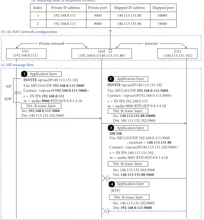
Figure 1(b) shows the NAT configuration in an SHE. In this figure, an SHE (i.e., private network) connects to Internet (i.e., the public IP network) through an NAT (i.e., home gateway). The private IP addresses 192.168.0.0/24 are assigned to the hosts in the private IP network. The IP address of the public network interface card (NIC) for the NAT is 140.113.131.88.
(a) Mapping table (a simplified version)
Index 1 2
Private IP address 192.168.0.111 192.168.0.111
Private port 5060 9000
Mapped IP address 140.113.131.88 140.113.131.88
Mapped port 10080 19000
(b) An NAT network configuration
UA1
(192.168.0.111) (192.168.0.1NAT/140.113.131.88)
UA2 (140.113.131.102)
Private network Internet
(c) SIP message flow
SIP
SDP
1 Application layer
INVITEsip:ua2@140.113.131.102 Via: SIP/2.0/UDP192.168.0.111:5060
Contact:<sip:ua1@192.168.0.111:5060>
c=IN IP4192.168.0.111
m=audio9000RTP/AVP 0 8 3 4 18 Net. & trans. layer
Src:192.168.0.111:5060
Dst: 140.113.131.102:5060
2 Application layer
INVITEsip:ua2@140.113.131.102 Via: SIP/2.0/UDP192.168.0.111:5060
Contact:<sip:ua1@192.168.0.111:5060> c=IN IP4 192.168.0.111
m=audio 9000 RTP/AVP 0 8 3 4 18 Net. & trans. layer
Src:140.113.131.88:10080
Dst: 140.113.131.102:5060
3 Application layer
200 OK
Via: SIP/2.0/UDP 192.168.0.111:5060 ; received=140.113.131.88
Contact:<sip:ua2@140.113.131.102:5060> c=IN IP4 140.113.131.102
m=audio 9002 RTP/AVP 0 8 3 4 18 Net. & trans. layer
Src: 140.113.131.102:5060 Dst:140.113.131.88:5060
4 Application layer [RTP]
Net. & trans. layer Src: 140.113.131.102:9002 Dst:192.168.0.111:9000
Figure1: SIP message flow with standard NAT mechanism.
a packet from UA2 (with the destination IP address/port 140.113.131.88:10080), it retrieves the mapping table to translate the IP address/port to 192.168.0.111:5060 and sends the packet to UA1. The above NAT mechanism only translates theIP information(i.e., the IP address and the port number) at the network and the transport layers. It does not translate the IP information carried in the content of an SIP message. Therefore, the application-layer IP information is not consistent when the SIP message traverses the NAT. This issue is further elaborated as follows. Several header fields in an SIP message contain IP information related to SIP message delivery. For example,
(i) the Viaheader field indicates the SIP nodes visited by an SIP request so far; the reverse direction of the path should be followed to route the responses for this request,
(ii) theContact header field indicates the address where the other party can send subsequent requests.
Two Session Description Protocol (SDP) fields in the SIP body provide IP information for media sessions [9].
(i) The IP address for the connection is provided in the
cfield.
(ii) The port number for the media information is provided in themfield.
Figure 1(c) illustrates SIP message delivery between UA1 and UA2 through the standard NAT. Suppose that UA1 sends an SIP INVITE message (Figure 1(1)) to UA2. In this message, both theViaand theContactheader fields contain UA1’s IP address 192.168.0.111 and port 5060. For the RTP media session, 192.168.0.111 and 9000 are recorded in thec
packet with the source IP address/port 192.168.0.111:5060. At the NAT, the source IP address/port of the packet is translated to 140.113.131.88:10080 (Figure 1(2)). However, the application layer content (i.e., the SIP message) is left unchanged.
Upon receipt of the INVITE message, UA2 creates a 200 OK message where the Via header field (i.e., 192.168.0.111:5060) is copied from the INVITE message. Then UA2 adds the received parameter with the value 140.113.131.88 to theViaheader field. UA2 replies the 200 OK message by using the address and the port number in the
Viaheader field (Figure 1(3)). Since 5060 is not a correct port number in the NAT’s mapping table, this message cannot be delivered to the destination (i.e., UA1). Also, the RTP packets will be delivered to 192.168.0.111:9000 (Figure 1(4)) as designated by the c and the m fields in the INVITE message. Consequently, the destination is unreachable from the public IP network for this SIP call.
The SIP/RTP NAT traversing issue can be resolved by two approaches. In theSHA-basedsolution, the application layer IP information translation is performed at the SHAs. In theserver-basedsolution, the translation is performed at a server in the public IP network. Note that in the SHA-based solution, the SHA may still need to interact with a server to obtain the IP information mappings.
Examples for SHA-based solutions include Static Route [10], Universal Plug and Play (UPnP) [11], Simple Traversal of UDP through NATs (STUN) [12], STUN Relay Usage [13], Interactive Connectivity Establishment (ICE) [14], and Realm Specific IP (RSIP) [15]. Examples for server-based solutions include Application Layer Gateway (ALG) [16], Session Border Controller (SBC) [17, 18], and midcom [19]. This article focuses on several widely SIP/RTP NAT traversing solutions used in SHEs, and shows their tradeoffs.
2. STATIC ROUTE
In Static Route [10], the application layer address translation is performed at the SHA (i.e., an SIP UA) in a smart home environment (i.e., private IP network), and the standard NAT is used to translate the IP-layer address. Both the SHA and the NAT need to configure an SIP mapping (e.g., entry 1 in Figure 1(a)) and an RTP mapping (e.g., entry 2 in Figure 1(a)). If the SHA is engaged in multiple media streams (e.g., audio plus video), extra RTP mappings are required.
Figure 2illustrates SIP message delivery between UA1 (in the private IP network) and UA2 (in the public IP network) based on Static Route. The IP address settings for UA1, UA2, and the NAT are the same as those inFigure 1. Initially, the SIP mapping and the RTP mapping are configured in both UA1 and the NAT.
Whenever UA1 sends an INVITE message to the UA2 (Figure 2(1)), the message is carried by an IP packet with the source IP address/port 192.168.0.111:5060. The IP address/port reserved for the media session is 192.168.0.111: 9000. The private IP information is not shown in the application layer content. Instead, through the mapping table in UA1, the private IP address/port is replaced by the public IP address/port 140.113.131.88:10080, which are
filled in both the Via and the Contact header fields. Also, the public IP address/port 140.113.131.88:19000 for RTP are filled in the c and the m fields, respectively. At the NAT, the source IP address/port of the packet is translated from 192.168.0.111:5060 to 140.113.131.88:10080 (Figure 2(2)). The application layer content is left unchanged.
Upon receipt of the INVITE message, UA2 replies a 200 OK message (Figure 2(3)). The Via header field (i.e., 140.113.131.88:10080) in the INVITE message (Figure 2(2)) is copied to the 200 OK message as the destination of the message. Then the 200 OK message is sent to the NAT. When the NAT receives the 200 OK message, it retrieves the mapping table, translates the destination IP address/port from 140.113.131.88:10080 to 192.168.0.111:5060, and sends the packet to UA1 (Figure 2(4)).
The ACK message (with 140.113.131.88:10080 in the
Via and the Contact header fields) is delivered to UA2 (Figure 2(5) and (6)) just like the INVITE message. The RTP packets from UA1 to UA2 are delivered to 140.113.131.102: 9002 (Figure 2(7)) as designated by thec and the mfields in the 200 OK message (Figure 2(4)). At the NAT, the source IP addresses/ports of these packets are translated from 192.168.0.111:9000 to 140.113.131.88:19000. These packets are then sent to UA2 (Figure 2(8)). For the RTP media data sent from UA2 to UA1 (Figure 2(9)), they are carried by IP packets with destination IP address/port 140.113.131.88:19000. This destination IP information is specified in the c and the m fields in the INVITE message (Figure 2(2)). Upon receipt of the RTP packets, the NAT translates the destination IP address/port from 140.113.131.88:19000 to 192.168.0.111:9000 and sends the packets to UA1 (Figure 2(10)).
3. UNIVERSAL PLUG AND PLAY (UPnP)
Manual configuration of Static Route can be automated by Universal Plug and Play (UPnP) [11]. UPnP is a network protocol for automatic discovery and configuration when a certain device (i.e., an UPnP client) is online. Therefore, IP information mappings in both the UA and the NAT can be automatically established by the UPnP protocol. Then all SIP/RTP packets traverse over the NAT with the same procedure described inSection 2.
An UPnP system typically consists of several UPnP clients and an Internet Gateway Device (IGD). In the SHE, a smart home appliance is an UPnP client and a home gateway plays the role as an IGD. The IGD joins in the multicast group 239.255.255.250 and listens on port 1900 for the requests issued by the UPnP clients. The UPnP messages are exchanged through the Hypertext Transfer Protocol (HTTP). Figure 3 illustrates how the mapping in entry 1 of Figure 1(a) is established by the UPnP messages exchanged between UA1 (an UPnP client) and the NAT (i.e., home gateway). The IP address settings for UA1 and the NAT are the same as those inFigure 1. The message flow inFigure 3is described as follows.
UA1
(192.168.0.111) (192.168.0.1NAT/140.113.131.88)
UA2 (140.113.131.102)
Private network Internet
SIP
SDP
1 Application layer
INVITEsip:ua2@140.113.131.102 Via: SIP/2.0/UDP140.113.131.88:10080
Contact:<sip:ua1@140.113.131.88:10080>
c=IN IP4140.113.131.88
m=audio19000RTP/AVP 0 8 3 4 18 Net. & trans. layer
Src:192.168.0.111:5060
Dst: 140.113.131.102:5060
2 Application layer
INVITEsip:ua2@140.113.131.102 Via: SIP/2.0/UDP 140.113.131.88:10080 Contact:<sip:ua1@140.113.131.88:10080> c=IN IP4 140.113.131.88
m=audio 19000 RTP/AVP 0 8 3 4 18 Net. & trans. layer
Src:140.113.131.88:10080
Dst: 140.113.131.102:5060
4 Application layer
200 OK
Via: SIP/2.0/UDP 140.113.131.88:10080 Contact:<sip:ua2@140.113.131.102:5060> c=IN IP4 140.113.131.102
m=audio 9002 RTP/AVP 0 8 3 4 18 Net. & trans. layer
Src: 140.113.131.102:5060 Dst:192.168.0.111:5060
5 Application layer
ACKsip:ua2@140.113.131.102 Via: SIP/2.0/UDP140.113.131.88:10080
Contact:<sip:ua1@140.113.131.88:10080>
Net. & trans. layer Src: 192.168.0.111:5060 Dst: 140.113.131.102:5060
7 Application layer [RTP]
Net. & trans. layer Src:192.168.0.111:9000
Dst:140.113.131.102:9002
10 Application layer
[RTP]
Net. & trans. layer Src: 140.113.131.102:9002 Dst:192.168.0.111:9000
3 Application layer
200 OK
Via: SIP/2.0/UDP140.113.131.88:10080
Contact:<sip:ua2@140.113.131.102:5060> c=IN IP4 140.113.131.102
m=audio 9002 RTP/AVP 0 8 3 4 18 Net. & trans. layer
Src: 140.113.131.102:5060 Dst:140.113.131.88:10080
6 Application layer
ACKsip:ua2@140.113.131.102 Via: SIP/2.0/UDP 140.113.131.88:10080 Contact:<sip:ua1@140.113.131.88:10080>
Net. & trans. layer Src: 140.113.131.88:10080 Dst: 140.113.131.102:5060
8 Application layer [RTP]
Net. & trans. layer Src:140.113.131.88:19000
Dst: 140.113.131.102:9002 9 Application layer [RTP]
Net. & trans. layer Src: 140.113.131.102:9002 Dst:140.113.131.88:19000
Figure2: SIP/RTP NAT traversing: the static route solution.
239.255.255.250:1900) to find the NAT (i.e., the home gateway). M-SEARCH is a method defined by Simple Service Discovery Protocol (SSDP) for search requests.
Step 2. Upon receipt of the M-SEARCH message, the NAT returns its private location (i.e., 192.168.0.1:2869) to UA1 by filling the IP address/port in the payload of a unicast HTTP response (i.e., 200 OK). The IP information is then used as the destination of the messages sent from UA1 to the NAT.
Step 3. To retrieve the mapped IP address, UA1 sends an UPnP GetExternalIPAddress request (an HTTP POST message) to the NAT.
Step 4. The NAT then replies its public IP address (i.e., 140.113.131.88) to UA1 through an HTTP 200 OK message.
Private network SSDP: discover internet gateway device
Dst: 239.255.255.250:1900
Figure 3: UPnP message flow for establishing IP information mapping.
information and the mapped public port number in entry 1 ofFigure 1(a).
Step 6. If the proposed public port (i.e., 10080) is unused, the NAT confirms the mapping by an HTTP 200 OK message, and the procedure is completed.
In Steps 3 and4, the NAT informs UA1 of its public IP address (140.113.131.88 in Figure 1(b)). In Steps 5 and 6, the UA1 selects a port for the mapped IP address and informs the NAT of the private-to-public IP information mapping. Steps5and6allow the applications (e.g., SIP or FTP) to specify the well-known port numbers (e.g., 5060 or 21) at the NAT. The UPnP mechanism also supports the deletion of an IP information mapping. This feature enables applications to create short-lived IP information mappings for short session-based communications.
4. SIMPLE TRAVERSAL OF UDP THROUGH NATs (STUN)
Like UPnP, Simple Traversal of UDP through NATs (STUN) supports automatic configuration of private-to-public IP information mappings in both the UA and the NAT before an SIP call is set up. The SHA (i.e., a standard UA) is modified to accommodate the STUN mapping task. Unlike UPnP, STUN does not need any modification to the NAT (i.e., home gateway). However, an extra STUN server is required for IP information mappings. After the mappings are confirmed, all SIP/RTP packets traverse over the NAT with the same procedure described inSection 2. At this stage, the STUN server needs not to involve.
A STUN system is typically composed of a STUN server in the public IP network and several STUN clients in the private IP network [12]. The STUN server listens on port 3478 for requests. Figure 4illustrates how the mapping in
entry 1 ofFigure 1(a) is established. STUN messages in this figure are exchanged between UA1 (i.e., a SHA equipped with a STUN client) and the STUN server (with public IP address 140.113.131.62). The IP address settings for UA1 and the NAT (i.e., HG) are the same as those inFigure 1. The steps are described as follows.
Step 1. UA1 sends a STUN Binding Request message to the STUN server. This message is carried by an IP packet with source IP address/port 192.168.0.111:5060.
Step 2. At the NAT, the mapping in entry 1 of Figure 1(a) is established. According to the mapping table, the source IP address/port of the Binding Request message is translated from 192.168.0.111:5060 to 140.113.131.88:10080.
Step 3. Upon receipt of the message, the STUN server replies a STUN Binding Response message. In this message, the source IP address and port of the received packet (i.e., 140.113.131.88 and 10080) are filled in the IP and the Port fields of theMAPPED-ADDRESSattribute. This message is carried by an IP packet with the destination IP address/port 140.113.131.88:10080 and is sent to the NAT.
Step 4. The NAT retrieves the IP information mapping, translates the destination IP address/port from 140.113.131. 88:10080 to 192.168.0.111:5060, and sends the message to UA1. UA1 retrieves the IP address/port 140.113.131.88:10080 and creates an entry (i.e., entry 1 in Figure 1(a)) in its mapping table.
The NAT may eliminate the entries in its mapping table due to timeout. Therefore, the SHA should periodically transmit the STUN Binding Request messages to refresh the mappings.
5. INTERACTIVE CONNECTIVITY ESTABLISHMENT (ICE)
Interactive Connectivity Establishment (ICE) [14] provides NAT traversal for media sessions. It assumes that the NAT traversal for SIP is provided by other mechanisms such as STUN and sip outbound [20]. We use an example to demonstrate that an SHA only equipped with STUN can support RTP to traverse over a symmetric NAT. Suppose that UA1 equipped with a STUN client in the private IP network attempts to communicate with UA2 in the public IP network through a symmetric NAT. UA1 and UA2 support the ICE mechanism and are assigned the IP addresses/port numbers 192.168.0.111:9000 and 140.113.131.102:9002 for RTP delivery, respectively.
SDP fields (i.e., a = candidate: 1 1 UDP 2130706178 192.168.0.111 9000 typ local and a = candidate: 2 1 UDP 1694498562 140.113.131.88 19000 typ srflx raddr 192.168.0.111 rport 9000). Note that each SDP a field contains a number (e.g., 2130706178) to identify the priority for each IP address/port number and a larger number represents the higher priority. Upon receipt of the INVITE message, UA2 replies a 200 OK message carrying its IP address/port number in SDP a field (i.e., a = candidate: 1 1 UDP 2130706178 140.113.131.102 9002 typ local). After UA1 and UA2 exchange their IP addresses/port numbers through the offer/answer model, UA1 and UA2 start to perform the connectivity checking through the ICE mechanism. Specifically, UA1 sends an STUN binding request message to UA2 by using the source and desti-nation IP addresses/port numbers 192.168.0.111:9000 and 140.113.131.102:9002. Since the destination IP address/port number 140.113.131.102:9002 is different from that of the STUN server (i.e., 140.113.131.62:3478), the symmetric NAT translates the source IP address/port 192.168.0.111:9000 to a new port number 19002 (where the port number 19002 is different from the port number 19000 at the NAT).
Upon receipt of the STUNbinding requestmessage, UA2 retrieves the IP address/port number 140.113.131.88:19002 from its network header and the transport header. UA2 replies a STUN binding response message to UA1. At this time, UA1 completes the connectivity checking for the IP address/port number of UA2 (i.e., 140.113.131.102:9002). UA2 also performs the same connectivity checking for the IP addresses/port numbers of UA1 (i.e., 192.168.0.111:9000, 140.113.131.88:9000, and 140.113.131.88:9002). After the connectivity checking, UA1 confirms that the IP address/port number 140.113.131.102:9002 can be used to send the RTP packets to UA2. Similarly, UA2 confirms that the IP address/port number 140.113.131.88:9002 can be used to send the RTP packets to UA1. The above example illustrates UA1 only equipped with STUN can use the ICE mechanism to send/receive the RTP packets to/from UA2 through the symmetric NAT. If an SHA obtains multiple available IP addresses/port numbers from the connectivity checking, it will select the IP address/port number with the highest priority for RTP delivery.
6. SERVER-BASED NAT TRAVERSING SOLUTIONS
Application Layer Gateway (ALG) and Session Border Con-troller (SBC) are server-based solutions widely used in the SIP-based VoIP environments.
SIP-ALG typically collocates with the NAT to create the private-to-public IP information mappings and uses these mappings to translate the SIP messages, which works as follows.
When the NAT identifies an SIP message based on the source/destination port numbers (i.e., 5060) or the ASCII keyword “SIP/2.0” in the payload [21], it forwards the message to the SIP-ALG. The SIP-ALG first checks if an IP information mapping exists in the NAT’s mapping table. If so, the SIP-ALG translates the SIP Viaand the Contact
header fields based on the IP information mapping retrieved from the mapping table. Otherwise, the SIP-ALG invokes the NAT to create private-to-public IP information mapping and then uses it to translate the SIP header fields. If the SIP messages carrying SDP comes from the private IP network, the SIP-ALG interacts with the NAT to create IP information mappings for the RTP sessions and uses the mappings to translate the SDPcandmfields.
The Session Border Controller (SBC) [17] approach works as follows. Suppose that UA1 behind an NAT attempts to establish an RTP session to UA2 in the public IP network. Instead of establishing one RTP connection, an SBC located in the public IP network between the NAT and UA2 sets up two RTP subsessions: the UA1-SBC subsession and the SBC-UA2 subsession. Suppose that UA1 is assigned the IP address/port number 192.168.0.111:5060 for SIP delivery and 192.168.0.111:9000 for RTP delivery. UA2 is assigned 140.113.131.102:5060 for SIP delivery and 140.113.131.102:9002 for RTP delivery. The SBC is assigned the public IP address 140.113.131.7, and the NAT is assigned a public IP address 140.113.131.88. At the NAT, the pri-vate IP address/port number for SIP 192.168.0.111:5060 is mapped to 140.113.131.88:10080. Similarly, the private IP address/port number for RTP 192.168.0.111:9000 is mapped to 140.113.131.88:19000. To solve the SIP NAT traversing issue, UA1 sets the SBC as its outbound SIP proxy before any SIP message is issued. Therefore, all SIP messages sent from UA1 to UA2 will arrive at the SBC first.
For the INVITE message from UA1, the SBC finds that the IP header (i.e., 192.168.0.111) and SIP header (i.e., 140.113.131.88) are different (i.e., the message is sent from the private IP network). Therefore, the SBC adds the
receivedparameter 140.113.131.88 and therport parameter 10080 in the Via header field. These two parameters will serve as the private-to-public IP information mapping. The SBC also replaces the private IP address/port number 192.168.0.111:9000 in the SDPc andmfields by the SBC’s public IP address/port 140.113.131.7:8000 (i.e., port 8000 is used in the SBC for the SBC-UA2 RTP subsession). Then the SBC forwards the INVITE message to UA2. UA2 copies theViaheader fields of the INVITE message into a 200 OK message with SDP (where thecfield contains the IP address 140.113.131.102 and themfield contains the port number 9002) and replies this message to UA1 through the SBC. Upon receipt of the 200 OK message, the SBC translates the SDP c andm fields by the SBC’s IP address/port number 140.113.131.7:8002 (i.e., port 8002 is used in the SBC for the UA1-SBC RTP sub-session). Then the SBC forwards the 200 OK message to UA1 according to thereceivedand therport
parameters. In the summary, the SBC utilizes thereceivedand therport parameters to solve the SIP NAT traversing issue. The RTP traversing issue is resolved by breaking the UA1-UA2 session into the UA1-SBC subsession and the SBC-UA1-UA2 subsession.
7. COMPARISON
Private network Internet UA1 (STUN client)
(192.168.0.111) (192.168.0.1NAT/140.113.131.88)
STUN server (140.113.131.62) 1 Binding Request
Src:192.168.0.111:5060
Dst: 140.113.131.62:3478
2 Binding Request Src:140.113.131.88:10080
Dst: 140.113.131.62:3478
4 Binding Response
MAPPED-ADDRESS IP 140.113.131.88 Port 10080
Src: 140.113.131.62:3478 Dst:192.168.0.111:5060
3 Binding Response
MAPPED-ADDRESS IP140.113.131.88
Port10080
Src: 140.113.131.62:3478 Dst:140.113.131.88:10080
Figure4: STUN message flow for establishing IP information mapping.
Table1: Time complexities of the NAT traversing mechanisms for SIP/RTP.
NAT traversing mechanism IP information mapping establishment Call setup RTP latency
Static route Manual setup 71 ms 0.7 ms
UPnP 261 ms 71 ms 0.7 ms
STUN 27 ms 71 ms 0.7 ms
SIP-ALG N/A 96 ms 0.7 ms
SBC N/A 96 ms 4.3 ms
7.1. SHA modification
For Static Route, UPnP, and STUN, the SHA (i.e., a standard SIP UA) is modified to perform two tasks. In the first task, the (SIP/RTP related) IP information mappings at the NAT are obtained through manual setting, UPnP, or STUN protocols. In the second task, the SHA translates the IP information in the SIP messages. For ICE, both the calling and called SHAs are equipped with the ICE software. For SIP-ALG and SBC, the SHA does not require any modification (except for outbound SIP proxy setting in SBC).
7.2. Scope of NATs supported
For Static Route, ICE, and SBC, the NATs need not be modified. In UPnP and SIP-ALG, an agent should be collocated with the home gateway to serve as an IGD or an SIP-ALG. STUN does not support SIP/RTP traversal over symmetric NATs. In a symmetric NAT, the source port mapping is affected by both the source and the destination IP addresses/port numbers. In other words, two packets (sent from the smart home environment to Internet) with the same private source IP but different destination IPs would be translated to the same (public) source IP address but dif-ferent source ports. Therefore, the IP information mappings created through the STUNbinding request/responsemessages (stored in the SHA’s mapping table) are different from those (stored in the home gateway) for the SIP/RTP packets, and therefore, cannot be delivered to the SHA correctly.
7.3. Multilayer NAT traversal
When an SHA resides in a private network within another private network (therefore, there are multilayer NATs), all
solutions but UPnP still support NAT traversing for SIP/RTP. UPnP does not work because the UPnP client can only identify the NAT in the innermost layer. It does not have any knowledge to pass through the outerlayer NATs.
7.4. Extra server
Static Route and ICE do not require any extra server. STUN and SBC require extra servers. In UPnP, the home gateway is modified as an UPnP server. SIP-ALG typically resides in the home gateway.
7.5. Ease of configuration
Since the IP information mappings are automatically estab-lished by UPnP, ICE, and SIP-ALG, these mechanisms do not incur any configuration cost. In STUN, a user configures the server address and the username/password for authentication. In SBC, an SHA sets the SBC as the outbound SIP proxy. On the other hand, a Static Route user should manually configure the IP information mappings for SIP/RTP in both the SHA and the home gateway.
7.6. Security issues
NAT traversing solutions, this problem is directly resolved by standard NAT attack detection mechanisms. However, without extra authentication, UPnP cannot resolve this issue because a fake UPnP client can create an IP information mapping in the NAT (i.e., home gateway) for a legal SHA, and the packets sent to the public IP address/port of the mapping are always forwarded to attack the SHA until the mapping is explicitly deleted by the UPnP client. UPnP Forum has proposed a solution that has not been widely used in commercial NATs [22,23].
Also, secure transport for SIP/RTP is maintained in the SHA-based solutions. If SIP messages are encrypted, ALG cannot translate the messages. Similarly, SBC does not provide secure end-to-end transport. Instead, it provides secure transport for the two RTP subsessions. Therefore, the information delivered in the SIP/RTP sessions may be leaked at the SBC.
We conduct measurements in an experimental envi-ronment where the SHA (i.e., UA1) in the smart home environment (i.e., private IP network) connects to the home gateway (i.e., NAT) through a hub. The other device (i.e., UA2), the STUN server, and the SBC reside in the public IP network (i.e., Internet) and connect to the NAT through another hub.
Table 1shows the time complexities of the mechanisms discussed in this article except for ICE. Since ICE utilizes the mechanisms described in this paper, the costs for IP information establishment and RTP latency are the same as the mechanism utilized in ICE. The call setup latency for ICE is not a fixed value, which depends on how many IP addresses and port numbers are checked by ICE.
The table indicates that UPnP has the longest IP informa-tion mapping time. In terms of SIP setup and RTP delivery, Static Route, UPnP, and STUN are better than the server-based solutions.
8. CONCLUSIONS
This article investigated four SHA-based (Static Route, UPnP, STUN, and ICE) and two server-based (SIP-ALG and SBC) NAT traversing solutions in smart home environments. Our study indicates that Static Route requires manual setting, which is considered inefficient. UPnP automates Static Route, requires the modification on home gateways, cannot traverse over multilayer NATs, and is not secure as the other approaches. STUN also automates Static Route, requires an extra server, and cannot traverse symmetric NAT. ICE supports symmetric NAT traversal and automates selection of NAT traversing mechanisms for RTP sessions by cooperating with other solutions. Both SIP-ALG and SBC automate translation of SIP messages without any modification to SHAs (i.e., SIP UAs). The home gateway needs to be modified to accommodate the SIP-ALG. The call setup time and the RTP latency for the server-based solutions are longer than that for the SHA-based solutions. In summary, there is no SIP/RTP NAT traversing solution that is better than others in all aspects. Users/operators should deploy appropriate NAT traversing solutions based on their needs.
ACKNOWLEDGMENTS
The work of W.-E. Chen and H.-C. Chao was sponsored in part by NSC 96-2218-E-197-004, NSC 96-2623-7-259-004-IT, NTP IMS Project under Grant no. 95-2219-E-009-019, NCHC Project, and ITRI/NCTU Joint Research Center.
REFERENCES
[1] Y.-J. Lin, H. A. Latchman, L. Minkyu, and S. Katar, “A power line communication network infrastructure for the smart home,IEEE Wireless Communications, vol. 9, no. 6, pp. 104111, 2002.
[2] J. Rosenberg, H. Schulzrinne, G. Camarillo, et al., “SIP: session initiation protocol,” June 2002, RFC 3261, IETF.
[3] P. Belimpasakis, A. Saaranen, and R. Walsh, “Home DNS: experiences with seamless remote access to home services,” in Proceedings of the IEEE International Symposium on a World of Wireless, Mobile and Multimedia Networks (WoWMoM ’07), pp. 18, Espoo, Finland, June 2007.
[4] T. Okugawa, H. Masutani, and I. Yoda, “A home net-work service environment for wide-area communications,” inProceedings of Asia-Pacific Conference on Communications (APCC ’05), pp. 1418, Perth, Australia, October 2005. [5] B.-C. Cheng, H. Chen, and R.-Y. Tseng, “Context-aware
gateway for ubiquitous SIP-based services in smart homes,” in Proceedings of the International Conference on Hybrid Information Technology (ICHIT ’06), vol. 2, pp. 374381, Cheju Island, Korea, November 2006.
[6] Y.-J. Oh, E.-H. Paik, and K.-R. Park, “Design of a SIP-based real-time visitor communication and door control architecture using a home gateway,” IEEE Transactions on Consumer Electronics, vol. 52, no. 4, pp. 12561260, 2006. [7] I. Han, H.-S. Park, Y.-W. Choi, K.-R. Park, et al.,
“Four-way video conference in home server for digital home,” in Proceedings of 10th IEEE International Symposium on Consumer Electronics (ISCE ’06), pp. 16, Petersburg, Russia, July 2006.
[8] P. Srisuresh and M. Holdrege, “IP network address translator (NAT) terminology and considerations,” August 1999, RFC 2663, IETF.
[9] M. Handley, V. Jacobson, and C. Perkins, “SDP: session description protocol,” July 2006, RFC 4566, IETF.
[10] Snom VoIP-telephones, “Solutions for NAT traversal in SIP environment,” http://old.iptel.org/info/products/etc/snom-stun.pdf.
[11] UPnPTM Forum,http://www.upnp.org/.
[12] J. Rosenberg, R. Mahy, P. Matthews, and D. Wing, “Session traversal utilities for (NAT) (STUN),” November 2007, draft-ietf-behave-rfc3489bis-13.
[13] J. Rosenberg, R. Mahy, P. Matthews, and D. Wing, “Traversal using relays around NAT (TURN): relay extensions to session-Traversal utilities for NAT (STUN),” November 2007, draft-ietf-behave-turn-05.
[14] J. Rosenberg, “Interactive interactive connectivity establish-ment (ICE): a protocol for network addressTranslator (NAT) traversal for offer/answer protocols,” October 2007, draft-ietf-mmusic-ice-19.
[15] M. Borella, D. Grabelsky, J. Lo, and K. Taniguchi, “Realm specific IP: protocol specification,” October 2001, RFC 3103, IETF.
all-IP environment,”IEEE Journal of Selected Areas in Commu-nications, vol. 23, no. 11, pp. 21522160, 2005.
[17] J. Hautakorpi, “Requirements from SIP (Session Initiation Protocol) session border control deployments,” April 2007, draft-ietf-sipping-sbc-funcs-03.
[18] J. Rosenberg and H. Schulzrinne, “An extension to the Session Initiation Protocol (SIP) for symmetric response routing,” August 2003, RFC 3581, IETF.
[19] P. Srisuresh, J. Kuthan, J. Rosenberg, A. Molitor, and A. Rayhan, “Middlebox communication architecture and frame-work,” August 2002, RFC 3303, IETF.
[20] C. Jennings and R. Mahy, “Managing client initiated connec-tions in the session initiation protocol (SIP),” November 2007, draft-ietf-sip-outbound-11.
[21] W.-E. Chen, Y.-H. Sung, and Y.-B. Lin, “SIPv6 analyzer: an analysis tool for 3GPP IMS services,”Wireless Communications and Mobile Computing, vol. 8, no. 2, pp. 245253, 2006. [22] C. Ellison, “Security console: 1 service template,” November
2003, Technical report, UPnPTM Forum.