Marcin Zych1,*, Robert Hanus2, Marek Jaszczur3, Volodymyr Mosorov4, and Dariusz Świsulski5
1 AGH University Science and Technology, Faculty of Geology, Geophysics and Environmental Protection, 30-059 Kraków, Poland 2Rzeszów University of Technology, Faculty of Electrical and Computer Engineering, 35-959 Rzeszów, Poland
3AGH University Science and Technology, Faculty of Energy and Fuels, 30-059 Kraków, Poland 4Łódź University of Technology, Institute of Applied Computer Science, 90-924 Łódź, Poland
5Gdańsk University of Technology, Faculty of Electrical and Control Engineering, 80-233 Gdańsk, Poland
Abstract. To determine the parameters of two-phase flows using radioisotopes, usually two detectors are used. Knowing the distance between them, the velocity of the dispersed phase is calculated based on time delay estimation. Such a measurement system requires the use of two gamma-ray sealed sources. But in some situations it is also possible to determine velocity of dispersed phase using only one scintillation probe and one gamma-ray source. However, this requires proper signal analysis and prior calibration. This may also cause larger measurement errors. On the other hand, it allows measurements in hard to reach areas where there is often no place for the second detector. Additionally, by performing a previous calibration, it is possible to determine the void fraction or concentration of the selected phase. In this work an autocorrelation function was used to analyze the signal from the scintillation detector, which allowed for the determination of air velocities in slug and plug flows with an accuracy of 8.5%. Based on the analysis of the same signal, a void fraction with error of 15% was determined.
1 Introduction
Radioisotope meters in flow mixtures studies of two and multiple phases are most commonly used as single-mode absorption spectrometric systems [1-5]. With them, after the appropriate calibration, one can measure the average density of the flowing mixture, void fraction or concentration of one of the phases. In addition, the flow type can also be recognized by analyzing the signal from the detector [5].
Up-to-date single-detector solutions do not allow to determine another important flow parameter, which is the velocity of the dispersed phase. Only systems extended by two or more detectors allow to measure this quantity [6-10].
The article presents the method of determining two parameters in a single detector system for liquid-gas flow: average velocity and void fraction. The air velocity was determined by the analysis of the autocorrelation function (ACF) of the detector signal. This method requires prior calibration for standard air velocity values. Based on analysis of the same signal, the void fraction was also determined. Also, setting this parameter required a prior calibration.
2 Experimental set-up
The results of the measurements obtained at the research facility located in the Sediment Laboratory of the
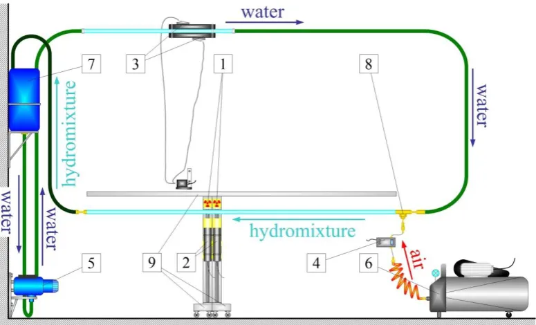
Faculty of Geology, Geophysics and Environmental Protection of AGH - UST in Krakow [9] were used. The installation diagram is shown in Fig. 1. Using this installation, liquid-gas flows can be tested using single- and dual-detectors. The configuration included two radiometric sets composed of gamma radiation Am-241 (1) with 3.7 GBq activity in lead collimators and two scintillation probes (2) with 2" × 2" NaI(Tl) crystals. Moving the system along the pipeline allows for the shift system (9). Water flow control is possible through an inverter mounted on a flow pump (5), and an ultrasonic meter (3). As a result, the flow velocity of the water could be adjusted in the range (0.9 ÷ 3.0) m/s. A two-phase water-air mixture is obtained by dispensing air from the compressor (6) through an injector (8) to a 4.5 m horizontal pipeline. The amount of air injected was determined using a Brooks 4800 (4) flow controller. Measurements were made at an airflow of 10.73 l/min. The venting of the installation takes place through the expansion tank (7). Photographic documentation was also performed during the measurements, the analysis of which allows to determine the type of flow.
Fig. 1. Schema oflaboratory experimental set-up: 1 –sealed Am-241 sources with collimators, 2 – scintillation probes, 3 – ultrasonic flow meter of water, 4 – mass flow meter of air, 5 – pump with power inverter, 6 – compressor 50l, 7 – expansion tank, 8 – injector, 9 – shift system.
3 Measurement of selected parameters
of liquid-gas flow
3.1 Air velocity measurement
Typically, two sets of source-probe located at a known distance from each other are used in radioisotope liquid-gas flow measurements. The average velocity of the dispersed phase is calculated based on the time delay of the obtained signals, and the known distance of the probes [8-10,13]. In this work the above method was used to determine the reference air velocity υA.
The main purpose of the research was to investigate the possibility of using the autocorrelation function to measure the velocity of the dispersed phase in a single-detector system. The ACF for the discrete values of the signal x(n) is defined by the relation [12,13]:
1
0
1 N
n
xx x n x n
N
R (1)
where: Rxx(τ) – autocorrelation function, τ – time delay, N – number of samples, x(n) – digital signal from the probe nt t
, t
– time of measurement, t – sampling time. The most frequently used is the normalized ACF: 2
x xx xx
R
(2)
where: ρxx(τ) – normalized ACF, σx – standard deviation of analyzed signal.
Such prepared experiment enabled the ACF sensitivity to be checked for changes to the velocity of the gas phase in the pipeline.
Fig. 2 shows an example of an ACF waveform for a measurement in which the mean water velocity was υW = 2.05 m/s and the average air velocity υA = 1.732 m/s. The following parameter values were adopted: N=180000, t = 1 ms.
The studies show that a change in velocity of the air passage changes the ACF indicated in Fig. 2 by a red frame. This fragment is shown enlarged in Fig. 3. As the curve resembles half of a normal distribution, it has been found that a suitable parameter for determining the velocity of the gas phase may be a standard deviation σACF.
Fig. 2. Exemplary plot of ACF obtained in the selected experiment. Red frame indicated the fragment which is related to the change of air velocity.
Fig. 3. Analyzed fragment of ACF from Fig. 2.
a)
b)
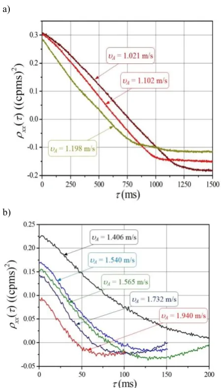
Fig. 4. Changing the ACF shape for a) slug flows ; b) plug flows.
Table 1 summarizes the results. Water velocity υW. was measured by ultrasonic flowmeter. Determined values of σACF and corresponding air velocity υA allow to make a calibration graph, which is shown in Fig. 5.
in
term
itten
1.59 71 1.406 0.054
pl
ug
1.78 44 1.540 0.061
1.82 41 1.565 0.064
2.05 32 1.732 0.070
2.19 26 1.940 0.079
Fig. 5. Calibration curve υA = f(σACF)
Based on the distribution of the points in Fig. 5, the relationship between air velocity and standard deviation σACF is obtained:
B
a exp A a exp
A ACF ACF
ACF
A
2 2
1 1
(3)
where: A1 = (4.7 ± 1.5) m/s; a1 = (11.5 ± 1.7) ms; A2 = (1260.443 ± 0.034) m/s; a2 = (1.600 ± 0.043)·106
ms; B = (-1258.9795 ± 0.0068) m/s.
3.2 Determination of void fraction
The publication [4] describes exactly the method of calibration of the gamma-absorption system for liquid-gas two-phase flows to determine average void fraction α for air. Because the experiments used in this article have changed the geometry of the measurement section for the radiometric set, the calibration was re-done. As a result, the calibration relationship shown in Fig. 6 was obtained.
Fig. 6.The relationship between the natural logarithm of the gamma radiation intensity I (recorded by scintillation probe) and the void fraction .
The dependency ln(I) = f(α), after fitting the least squares method, can be described by the equation:
I c ln I0
ln (4)
where: I – intensity of gamma radiation recorded by the probe, c = 0.381 ± 0.012; ln(I0) = 3.0630 ± 0.0080; I0 – the radiation intensity at the pipeline completely filled with water. The determination factor is: R2 = 0.993.
Table 2. Valuation of void fraction α and uncertainty values
u(α) for the analyzed experiments. υW
(m/s) (-) α u(-) (α)
1.24 0.276 0.023
1.33 0.250 0.022
1.41 0.228 0.022
1.59 0.202 0.022
1.78 0.199 0.022
1.82 0.180 0.022
2.05 0.164 0.022
2.19 0.155 0.021
The dependence (4) is more universal than Equation (3) because after measuring the intensity of radiation I0 it can be used to determine the average value of α irrespective of the flow type of water-air mixture for pipelines of the same diameter and of the same material as the test installation. The measurement system used allows the void fraction to be evaluated to an accuracy of approximately 15%. Table 2 summarizes the mean α
values for the analyzed experiments. Uncertainty values u(α) were determined on the basis of the law of uncertainty propagation based on formula (4) [14].
4 Conclusions
The paper presents the method for determining the velocity of the dispersed phase and the void fraction for liquid-gas flow using a single detector gamma radiation absorption system.
On the basis of studies it was found that a single set of probe scintillation - sealed source of gamma radiation allows the determination of the above-mentioned size.
However, determining the velocity of the gas phase in a single-detector system requires prior calibration, which is troublesome. In addition, the results are more error-prone than with the two-detector system. An autocorrelation function was used to analyze the signal from the scintillation detector, which allowed the determination of air velocity to an accuracy of 8.5%. The presented studies show that the gas velocity can only be determined to a limited extent, i.e. for intermittent flows. In addition, based on the analysis of the same signal from the detector, a void fraction with accuracy of 15% was determined.
It should be emphasized that the studies of the one detector system should continue and the possibility of linking other statistical parameters to the airflow signal should be explored. This would increase the accuracy and extend the measurement capabilities. Such an operation is economically justified because one-detector systems are cheaper than multi-detectors. Additionally, while reducing costs, the radiation level is reduced, which is extremely important for the operation of this type of equipment.
Acknowledgment
The authors would like to thank dr Leszek Petryka for his cooperation during the measurements.
5. G.H. Roshani et al., Flow Meas. Instrum. 54, 39–45 (2017)
6. P.R. Tortora et al., Int. J. Multiphas. Flow 32, 972–
995 (2006)
7. H.J. Pant, et al., Appl. Radiat. Isotop. 67, 1609–1615 (2009)
8. R. Hanus et al., Flow Meas. Instrum. 40, 58–63 (2014)
9. R. Hanus, Int. J. Multiphas. Flow 72, 210–217 (2015) 10.M. Zych et al., Powder Technol. 318, 491–500
(2017)
11.R. Hanus et al., EPJ WoC 114, 02035 (2016)
12.J.S. Bendat, A.G. Piersol, Random data - analysis and measurement procedures (John Wiley, New York, 2010)
13.M.S. Beck, A. Plaskowski, Cross correlation flowmeters - their design and application (Adam Hilger, Bristol, 1987