A Lyapunov Function Based Control
Technique for the Stable operation of DG
Units in Smart Grid
Manjappa N1, Santhosh R2Assistant Professor, Dept. of EE, University of Vivesvaraya College of Engineering, Bangalore, Karnataka, India1 PG Student [PES], Dept. of EE, University of Vivesvaraya College of Engineering, Bangalore, Karnataka, India2
ABSTRACT: Renewable Energy is intermittent in nature and they don’t provide a continuous power flow to the power grid. The Smart Grid Environment is the situation where the automatic decision-making happens according to the situations like where the control has to be provided by the power processing units. The smart grid comprises of the smart meters, renewable energy resources, energy efficiency devices. This project is an attempt to develop the multifunctional control approach to stabilize the distributed generator output connected to the grid. The AC current side compensation and the DC voltage compensation of the DC link are the parameters to be considered for the stable operation of the distribution generator connected to the grid. Direct Lyaponav Control (DLC) is considered for the compensation control in this implementation. This control assures a continuous compensation of the current in the grid side and also continuous DC voltage compensation in the DC-link. This is carried out to assure that only the active power is utilized in the power grid, and all the reactive and the harmonic current is completely eliminated. Mat lab based simulation is carried out with both linear and non-linear load introduced in the grid.
KEYWORDS: Active power filter, Direct lyapunov control (DLC), voltage source converter, Power factor.
I.INTRODUCTION
Grid Synchronization is a major implementation where the renewable energy connected to the power grid is analysed. The distributed generators are those generators that are near the load points usually. The extra power is connected to the grid. Usual Distributed generators are renewable energy based and thus the power generated from that generator is not stable. Thus there are many control technique that has to be carried out to develop the stability in the generator output. In this project, the authors are introducing a multifunction control strategy based on the DLC technique, for a stable operation of the proposed model and the VSC control as the heart of the interfacing system between DG sources and the power grid. The impacts of instantaneous variable variations in the operation of DG systems are adequately considered in the proposed control plan, which is a new contribution of this control method in comparison with other existing strategies. Indeed, the contribution of this strategy in DG systems can be introduced as a new solution in the distribution grid, while compensating for the different issues needed concurrently during the connection of nonlinear loads to the utility grid. The AC current side compensation and the DC voltage compensation of the DC link are the parameters to be considered for the stable operation of the distribution generator connected to the grid. Direct Lyaponav Control (DLC) is considered for the compensation control in this implementation.
II.SYSTEM MODEL AND ASSUMPTIONS
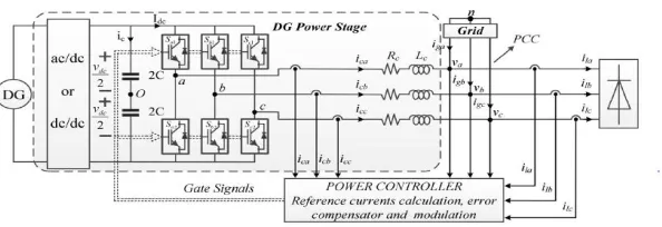
Figure 1 General Schematic diagram of the proposed model
A. DYNAMIC STATE ANALYSIS OF THE PROPOSED MODEL
For designing an applicable control scheme for the interfacing system, the dynamic state of the whole model should be evaluated precisely. By the application of the Kirchhoff’s voltage and current laws in both ac and dc sides of the interfaced converter, a general equation of the model can be obtained as
Wherevkn= vko−vno. By referring to Figure 5.1, the voltage relations between ac and dc sides of the interfacing system
can be mentioned as
By substituting (3) in (1), a set of equations for the dynamic behaviour of the proposed model in Fig 4.3 can be obtained, which is based on the switching state function of the interfaced converter as
By considering Seq as the switching state function, general dynamic equations for the ac and dc sides of the interfacing system can be expressed as
Equations (5) and (6) describe the behaviour of the proposed DG model during the integration time with power grid.
B. STEADY-STATE ANALYSIS OF THE PROPOSED MODEL
Dynamic state equations in (5) and (6) can be transformed into the dq reference frame by using the Park transformation matrix, which rotates at the grid angular frequency. By this technique, all the alternative variables of Figure 5.1 in fundamental frequency are converted to the dc values; then, filtering and controlling in the control loop of the model can be achieved easier.
By considering the direction of the reference vector of grid voltage in direction of d-axis, the q-component of grid voltage will be zero (vmq= 0) and reference voltage value will be equal to d-component of grid voltage (vm= vmd).
Assuming Irefd as the reference value of d-axis in current control loop of DG for injection of active power to the grid (Icd
= Irefd), and since that in rotating synchronous reference frame q component of load current is perpendicular on
d-component of voltage, Irefq will be the reference current of q-axis in DG current control loop, which provides the
required reactive power for the loads in both fundamental and harmonic frequencies (Icq= Irefq). The mentioned
assumptions are considered as the stability criteria in the proposed model and by substituting these assumptions in (7)– (9), and considering vr as the desired value of vdc and Seqds and Seqqs as the switching state values during the steady state
operating condition, a set of equations can be achieved for the steady-state operation of the proposed model as
The impacts of instantaneous variations in the values of reference current components should be considered in the control loop of DG to meet an appropriate compensation during the changes from dynamic to steady-state operating conditions. Consequently
By substituting (13) in (10) and (11), the switching state functions of the interfacing system from the dynamic to the steady-state operating conditions can be expressed as
By substituting obtained switching state function (12),(16)can be achieved as
III.DLC TECHNIQUE REPRESENTATION
DLC strategy is considered for the interfacing system control in the control loop of the model represented in Figure 1. DLC strategy is basically a nonlinear control theory without linearizing the nonlinearities in parameters of the equivalent mathematical system model, bringing a global asymptotic stability for the proposed model.
The scalar function in (17) is a general function for DLC technique, which is determined to validate the stability of the proposed model during DG interconnection into the power grid and parameter changes in the whole system.
dc-side of interfaced VSC. In addition, (17) demonstrates the total energy of the whole system in the controlled region, which should be dissipated for system stability. To reach this goal, (17) should fulfil the following criteria:
In order to guarantee a multifunction control technique for reaching a stable operating region for DG units during changes in the parameters of the whole system, the switching state functions of interfaced VSC in the proposed model should bedefined as
Seqd = Seqds + ∆ Seqd (19) Seqq = Seqqs + ∆ Seqq(20)
By substituting (14) and (15) in (7) and (8), time variable parts of (18) can be expanded as
Moreover, by substituting x1 = icd− Irefd, x2 = icq−Irefq, x3 = vdc−vr, (21)–(23) in (18), and considering the definitions in
(13), (24) can be obtained as
Equation (24) should have a negative value to meet the stability criteria during operation of the proposed DG model in a smart grid system. To reach this goal, all the terms in (24) should be analysed properly one-by-one. It is clear that the first and second terms of this equation have negative values; moreover, the switching state functions of the interfacing system can be defined to have a positive definite total energy and a flexible reflection against the dynamic changes by considering∆Seqd and ∆Seqq as
∆Seqd = γ (vricd− vdcIrefd) (25)
r cq dc refq
eqq
v
i
v
I
S
(26) .As a result, application of DLC technique can guarantee a stable operation for the proposed DG model during both dynamic and steady state operating conditions. Figure 2 shows the control block diagram of the proposed model based on DLC technique. The proposed control strategy which combines (14), (15), (25), and (26) can create a global asymptotic stable region for the DG operating areas.
IV.SPACE VECTOR PWM
This section briefly discusses the space vector PWM principle. This PWM method is frequently used in vector controlled and direct torque controlled drives. In vector controlled drive this technique is used for reference voltage generation when current control is exercised in rotating reference frame.
It is seen in the previous section that a three-phase VSI generates eight switching states which include six active and two zero states. These vectors form a hexagon which can be seen as consisting of six sectors spanning 60° each. The reference vector which represents three-phase sinusoidal voltage is generated using SVPWM by switching between two nearest active vectors and zero vector. To calculate the time of application of different vectors, consider Fig. 3, depicting the position of different available space vectors and the reference vector in the first sector.
Figure 3. Principle of space vector time calculation
. In order to obtain fixed switching frequency and optimum harmonic performance from SVPWM, each leg should change its sate only once in one switching period. This is achieved by applying zero state vector followed by two adjacent active state vector in half switching period. The next half of the switching period is the mirror image of the first half. The total switching period is divided into 7 parts, the zero vector is applied for 1/4thof the total zero vector time first followed by the application of active vectors for half of their application time and then again zero vector is applied for 1/4thof the zero vector time. This is then repeated in the next half of the switching period. This is how symmetrical SVPWM is obtained..
V. SYSTEM CONFIGURATION
Configuration should be represented as follows:
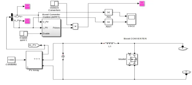
1) Configuration 1 represents Distributed Generation (DG) SOLAR DG, depicted in fig 4
2) Configuration 2 represents the generation of reference current generation, depicted in fig.5.
Fig.5.reference current generator
3) Configuration 3 represents the direct lyapunov control technique and SVPWM is included and analysed depicted in fig.6
Fig.6.Direct lyapunov control technique
4) Configuration 4 represents the nonlinear load is connected to the utility grid and DG integration, DLC proposed model
VI. SPECIFICATION OF DESIGN DATA
VII. RESULT AND DESCRIPTION.
Fig. 8 indicates the simulation results for the load, grid, and DG currents during these three operating times. As depicted.in this figure, during 0.1 < t (s) <0.2 all the load current components in both the dc and harmonic frequencies are supplied trough the DG and injected power from the utility grid to the load reduced to the zero value (Sload < SDG). But, while the second load is added up to the first load during 0.2 < t (s) <0.3, the maximum injected power from the DG to the grid is less than the required power for supplying the loads; then, the remaining power is compensated through the grid side. As shown in this figure, the injected current via the grid to the load is sinusoidal and free of harmonic frequencies during the load increment.
Fig.8. load,grid,and DG currents before and after DG integration to the grid ,and before and after the second load increment
A. POWER FACTOR EVALUATION
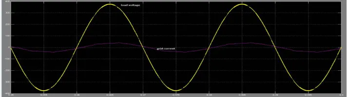
One of the main goals of the DLC strategy is to achieve a unit PF between grid current and load voltage. To reach this goal, total load reactive power should be generated by DG. Fig. 9 indicates the grid current and load voltage in phase (a) during the connection of additional load to the grid. As can be seen, grid current is in phase with load voltage, which confirms a unity value for the PF of the grid
B. FUNDAMENTAL AND THD VALUES OF GRID CURRENT
TABLE 2
Before compensation After compensation by DLC
technique using SVPWM
Peak current (A) Igrid1 Igrid2 Igrid3 Igrid1 Igrid2 Igrid3
Fundamental
frequency(50Hz) 36.02 36.02 36.2 21.35 20.93 20.88
THD % 16.48 16.46 16.47 1.62 1.51 1.45
As can be seen from table 2 THD of grid current is 16.48% during additional load increment but after interconnection of DG to grid THD reduced to 1.62 in phase Igrid1. Similarly Igrid2 and Igrid3 before and after compensation is shown in table 2.The results confirms the capability of proposed modelto compensatethe harmonic current components of nonlinear load
VI.CONCLUSION
A control plan based on DLC method has been developed for the integration of DG sources to the grid. The main objective of the proposed control technique was to prepare a secure and low cost energy for the loads from the dispersed sources of energy, specially based on the renewable energy sources. The main advantage of our proposed control technique over the other control techniques was its high performance for the compensation of active and reactive power changes and harmonic current components of nonlinear loads. By the utilization of the DLC technique, DG can provide continuous injection of maximum active power in grid frequency, all the reactive power and harmonic current components of grid-connected loads, via connection of distributed energy resources into the power grid. The proper application of this technique in a smart grid system can reduce the stress on the utility grid by injection of power from the DG source into the grid during the peak of demand, which can also decrease the cost of consumed energy from the customer’s point of view. The high performance of DLC technique has been validated through simulation and experimental test results during both dynamic and steady-state operating conditions, certifying the concept of DLC method as a multifunction control technique in DG technology, which is very important for the proper operation of sensitive loads in the power grid.
REFERENCES
[1] F. H. Guan, D. M. Zhao, X. Zhang, B. T. Shan, and Z. Liu, “Research on distributed generation technologies and its impacts on power system,” in Proc. IEEE Sustain. Power Genre. Supply, Nanjing, China, 2009, pp. 1–6.
[2] M. F. Akorede, H. Hizam, and E. Pouresmaeil, “Distributed energy resources and benefits to the environment,” Renew. Sustain. Energy Rev., vol. 14, no. 2, pp. 724–734, Feb. 2010.
[3] E. Pouresmaeil, D. Montesinos-Miracle, and O. Gomis-Bellmunt, “Control scheme of three-level NPC inverter for integration of renewable energy resources into AC grid,” IEEE Syst. J., vol. 6, no. 2, pp. 242–253, Jun. 2012.
[4] E. Pouresmaeil, O. Gomis-Bellmunt, D. Montesinos-Miracle, and J. Bergas-Jane, “Multilevel converters control for renewable energy integration to the power grid,” Energy, vol. 36, no. 2, pp. 950–963, Feb. 2011.
[5] F. Blaabjerg, R. Teodorescu, M. Liserre, and A. V. Timbus, “Overview of control and grid synchronization for distributed power generation systems,” IEEE Trans. Power Electron., vol. 53, no. 5, pp. 1398–1409, Oct. 2006.
[6] E. Pouresmaeil, C. Miguel-Espinar, M. Massot-Campos, D. Montesinos-Miracle, and O. Gomis-Bellmunt, “A control technique for integration of DG units to the electrical networks,” IEEETrans. Ind. Electron., vol. 60, no. 7, pp. 2881–2893, Jul. 2013.