1291 |
P a g e
A STUDY ON ANALYSIS & FABRICATION OF
AN ICE PLANT MODEL
Pankaj Kumar
1, Ujjwal Kumar Nayak
21
Mechanical Engineering Department, B.I.T. Sindri, (India)
2
Mechanical Engineering Department, B.I.T. Sindri, (India)
ABSTRACT
An ice plant is machine used in ice factory to produce ice at large scale. In this paper, analysis and fabrication
of ice plant is discussed. We have found Coefficient of Performance equals to 3.2 and net cooling produced per
hour to be 0.56 TR.
Keywords: COP, Refrigerating effect, Ton of refrigeration.
I INTRODUCTION
Ice manufacture is used for producing refrigeration effect to freeze potable water in standard cans placed in rectangular tank which is filled by brine. In other words definition of refrigeration is the removal of heat energy so that a space or material is colder than its surroundings. An ice plant based on same principle as a simple refrigeration system. An ice plant contains various parts such as compressor, condenser, receiver, expansion valve, and evaporator and refrigeration accumulator. It plays a vital role in preserving food, chemical, medicine, fisheries and providing appropriate temperature in working.
II COMPONENTS OF AN ICE PLANT
Following components are used in fabrication of Ice Plant: 1. Compressor
2. Condenser 3. Receiver
4. Expansion device 5. Evaporator 6. Chilling tank 7. Refrigerant 8. Pressure gauge.
Hermetically sealed compressor:
1292 |
P a g e
be cooled by the gas or vapour being compressed. The difference between the hermitic and semi-hermitic, is that hermetic uses a one piece welded steel casing that cannot be opened for repair.Fig. 01 Hermetically Sealed Compressor
Air cooled condenser:
An air cooled condenser is one in which the removal of heat is done by air. It consists of steel or copper tubing through which the refrigerant flows. The size of tube usually ranges from 6-mm to 18-mm outside diameter, depending upon the size of condenser. Generally copper tubes are used because of its excellent heat transfer ability. The condensers with steel tubes are used refrigerating systems. The tubes are usually provided with plate type fins to increase the surface area for heat transfer. The fins are usually made from aluminium because of its light weight. The fin spacing is quite wide to reduce dust clogging. The condensers with single row of tubing provide the most efficient heat transfer. This is because the air temperature rises at it passes through each row of tubing.
Capillary tube:
1293 |
P a g e
Evaporator:
The evaporator is an important device used in the low pressure side of the refrigeration system. The liquid refrigerant from the expansion valve enters into the evaporator where its boil and change into vapour. The function of the evaporator is to absorb heat from the surrounding location or medium which is to be cooled, by mean of a refrigerant. The temperature of the boiling refrigerant in the evaporator must always be less than that of the surrounding medium so that heat flows to the refrigerant. The evaporator becomes cold and remains cold due to the following two reasons:
1. The temperature of the evaporation coil is low due to the low temperature of the refrigerant inside the coil.
2. The low temperature of the refrigerant remains unchanged because any heat it absorbs is converted to latent heat as boiling proceeds.
Chilling Tank:
The main components of chilling tank are ice tank, insulation of ice tank and ice block. Ice tanks are made of such material as wood, steel or concrete. As wooden tanks do not last long enough and are liable to leak, they should preferably be made of steel well coated with waterproof paint. Tanks made of rein-forced concrete are also recommended as superior to those of wood. The ice tank contains the direct expansion coil equally distributed throughout the tank and these coils are submerged in brine.
Refrigerant:
Refrigerant used in this prototype model is R-134a and it is also known as Tetrafluoroethane
(
) from the family of HFC refrigerant.It exists in gas form when expose to the environment
as the boiling temperature is - 26.1°C.
Pressure Gauge:
This device is used to measure the pressure on low and high pressure side of the
compressor.
Bourdon type pressure gauge is used.
1294 |
P a g e
III FABRICATION AND ANALYSIS OF MODEL
The model is fabricated by the students involved in the project at HEAT ENGINE LABORATORY,B.I.T SINDRI.
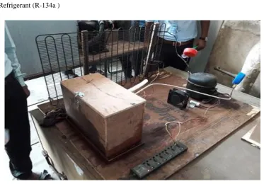
The prototype model of an ice plant has been fabricated consisting of
a) Compressor b) Condenser c) Capillary tube d) Evaporator e) Chilling tank f) Pressure gauge g) Fan
h) Refrigerant (R-134a )
Fig. 03 Image of fabricated ice plant
Specification and energy equation for different components:
Components
Specifications
Energy Equation
Compressor
Application with R-134a
Type- Hermetically sealed
compressor
Operating voltage - 180-260
volts
Capacity – 240 BTU1295 |
P a g e
Condenser
Single role air cooledcondenser
Filter Drier
Working pressure-(34.01 bar)
For use with CFC, HCFC,HFC,Expansion device
Type-capillary tube
Diameter of capillary tubeis 0.5 mm
Length of capillary tube is11 feet
Components
Specifications
Energy Equation
Evaporator coil
Diameter of copper coil – 1cm
Length of copper coil—1 m
Heat transfer rate at evaporator or refrigeration
capacity
is given by
Chilling Tank
Dimensions Length-13cm Breadth-7cm Height-9cm
Insulation is done with the help of wood.
The Thickness of insulation is=1cmPressure guage
Pressure of 200 to 230 kg/ must be maintain at high pressure side.
and 20kg/ must be maintained at low side.
Fan/ Blower
Operating Voltage/Current – 220V/15amp.
1296 |
P a g e
IV OBSERVATION & CALCULATION
The coefficient of performance of refrigeration plantis given by the ratio of heat absorbed, by the refrigerant when passing through the evaporator or the system, to the working input to the compressor to compress the refrigeration.
During the run following data has been recorded:
Inlet temperature of compressor = -5.2
Outlet temperature of compressor = 62.3
Inlet pressure of compressor = 0.12 MPa Outlet pressure of compressor = 1.5 MPa
Temperature of the evaporator = -20.42
Temperature of the condenser = 55 Coefficient of performance:
COP =
=
= 395KJ/Kg
= 435KJ/Kg
COP =
=
= 3.2
Cooling produced per hour:
COP = 3.2
435-395
= 40KJ/Kg
Net cooling produced =
= 40
= 132.4 KJ/Kg
Net cooling produced per hour =
=
KJ/min
1297 |
P a g e
V RESULT AND DISCUSSION
In this prototype model the mixture of NaCl and water in the proportion of 1:3 is used. On analysis of an Ice plant model we take some assumption liketank is perfectly insulated and no heat loss from or to the chilling tank. Wehave found Coefficient of Performance equals to 3.2and Net cooling produced per hour to be 0.56 TR.
REFERENCES
[1]Domkundwar et al., A Course in Refrigeration and Air-Conditioning(Dhanpat Rai and Company pvt. Ltd.)