SPRING DURABILITY TESTING USING CAM
MECHANISM
Thanekar Prashant
1, Patil Amit
2, Gaikwad Akash
3, Garad Tulshiram
4,
Kote Atul
5, Shirgure Akash
62
Professors: Department of Mechanical Engineering, GSMCOE Balewadi Pune, (India)
,3,4,5,6
Department of Mechanical Engineering, GSMCOE Balewadi Pune, (India)
ABSTRACT
The main requirement of the mechanism is to test the component and to measure for long-term performance capacity of component. Durability testing is an essential step to predicting the life of component. It also help to reduce risk of selecting defective part or components.
To reduce the inspection time and to get accurate result, we are developing the cam mechanism. The main consideration is to reduce the inspection time and to get accurate result. Automation is done to reduce the manual work. Also the development of the mechanism has to be cost effective.
After the observation of the component to be test the main focus is on to which type of mechanism should be used to apply force on to the spring. The idea is to hold the job in the clamping device and to apply the force by the cam mechanism.
I. INTRODUCTION
The demand for the present day machine components to move in a prescribed exact path is rarely fulfilled by
connected members. Therefore, it is necessary to make use of the miscellaneous contour surface called “Cams”.
They play a vital role in almost all machines e.g. textile machine tools I.C. engines, printing etc.
Usually a cam mechanism is a single degree of freedom device. It is a case of higher pair with line contact.
The demands for more accurate cam profile manufacturing have resulted in many performance testing devices.
The main objective of the project is…
1. To check the durability of spring this is located in the car. It is situated in seat assembly of car.
2. Accurate checking of the durability of the spring of nearly about 6000 cycles.
II.
OBJECTIVES
To reduce the inspection time and to get accurate result, we are developing the cam mechanism. The main
consideration is to reduce the inspection time and to get accurate result. Automation is done to reduce the
manual work. Also the development of the mechanism has to be cost effective.
After the observation of the component to be test the main focus is on to which type of mechanism should be
used to apply force on to the spring. The idea is to hold the job in the clamping device and to apply the force by
For counting the number of cycle we use a capacitive proximity sensor with a relay and a counter to get digital
reading.
III METHODOLOGY
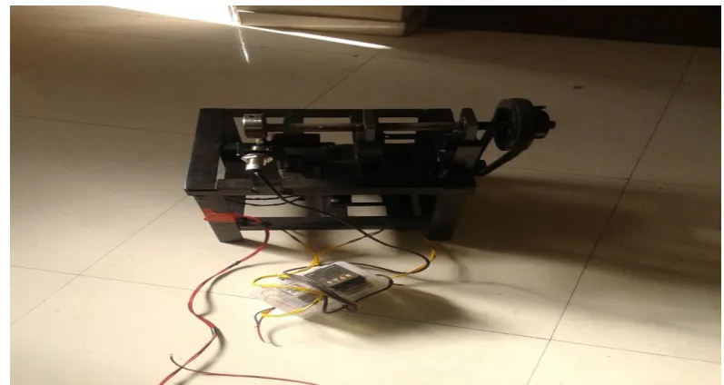
Transfer the rotary motion of the motor to the shaft with the help of belt and pulley drive mechanism. Two
bearing are used to support the shaft on which the cam is fitted. Screw is used to fit the cam on the shaft.
Clamping device is fitted below the cam which is used to hold the job throughout the process. A capacitive
proximity sensor is fitted on the side of the cam for counting process. Relay is used to stop the motor after 6000
cycle. Counter is used for counting the no. of cycles completed.
Fig :-SPRING DURABILITY TESTING USING CAM MECHANISM
IV. EQUIPMENT REQUIRED
4.1 Relay Sensor
We know that most of the high end industrial application devices have relays for their effective working. Relays
are simple switches which are operated both electrically and mechanically. Relays consist of an electromagnet
The switching mechanism is carried out with the help of the electromagnet. There are also other operating
principles for its working. But they differ according to their applications. Most of the devices have application
of relays.
4.2 Digital Counter
Technical specification:
Display : Seven segment LED; Height;0.5”
Digits : 4 digits
Sensor type : NPN/PNP
Operation Mode : ON delay / interval delay / auto reset
Counting direction : Up
Weight : 230 gms
4.3 Motor
Single phase AC motor
Power = ¼ hp = 180 watt, Speed = 0 to 1425 rpm
Motor is an single phase AC motor, power 180 watt, speed is continuously variable from 0 to1425 rpm. Motor is
a commutates motor i.e. the current to motor is supplied to motor by means of carbon brushes. The power input
to motor is varied by changing the current supply to these brushes by the electronic speed variator, thereby the
4.4 Cam and Follower
A disc type cam is used. Cam is fitted on shaft which rotate. Follower is used which follows motion of the cam.
A uniform motion cam moves the follower at the follower at the same rate of speed from beginning to the end of
stroke. They displacement diagram for uniform motion is a straight line with a constant slope. Thus, for constant
input speed of cam the velocity of the follower is also constant.
V. DESIGN CALCULATION
Motor Torque
P = 2
T=60X180/
T=1.185 Nm
DESIGN OF BELT DRIVE
Power = 180 watt,
Motor speed n = 1425 rpm,
Diameter of motor pulley D1 = 50 mm,
Diameter of IP shaft pulley D2 = 125 mm,
Belt section Pitch width
(Wp) mm
Nominal top
width W (mm)
Nominal
Top height T
(mm)
Pitch diameter
of pulley (mm)
Z 8.5 10 6 85
A 11 13 8 125
B 14 17 11 200
C 19 22 14 315
D 27 32 19 500
E 32 38 23 630
Table No.1- Dimensions of standard cross-section
Speed of shaft X D2 = Motor speed X D1
Speed of shaft = (1425 X 50) / 125
Speed of shaft = 570 rpm.
Selection of belt drive:
Determine pitch length of belt „L‟
L = 2C + (D+d)/2 + (D-d)^2/4C
Assume centre distance C = 250 mm,
L = 780 mm.
VI . CONCLUSION
The development of the Cam mechanism for durability testing of the spring used in the many
assemblies. It called for the application of various concepts of engineering.
The mechanism was developed and manufactured effectively by us. We arrangement and
manufacturing of the mechanism improve the performance and it was found to give fairly accurate
results, thereby eliminating the drawbacks encountered with manual testing process.
It therefore can be assert that the final spring will be permanent in meeting the standard performance
and assure reliability and satisfaction to the customer.
VII ACKNOLEDGEMENT
First and foremost we would like to thank Savitribai Phule, Pune University and Genba Sopanrao Moze College
of Engineering, Balewadi. for providing a course where we could learn all about Mechanical Engineering and
for allowing us to work with one of the most saught after and respected research institutes in country
We also sincerely thank to our Project guide Prof. A.M.Patil for his valuable guideline and showing for faith on
us and rendering unwavering support
It is pleasure in expressing hearty thanks Prof. A.A.Karyakarte Head of Department for allowing us to carry out
this project .Last and not the least ,we would like to thank the almighty for providing us the strength and support
afforded by the people that have helped us in every way possible
REFERENCES
[1.] Basaran Ozmen Etal/A novel methodology with testing and simulation for the
durability of leaf springs based on measured load collectives/Procedia Engineering 101 ( 2015 ) 363 – 371
[2.] LI Faxin and FENG Xianzhang /The Design of Parallel Combination for Cam Mechanism/ Procedia
Environmental Sciences 10 ( 2011 ) 1343 – 1349
[3.] Supriya Burgul/Literature Review on Design, Analysis and Fatigue Life of a Mechanical Spring Vol.2
Issue.7, july 2014, 76 – 83
[4.] John L. Porteiro/Spring design optimization with fatigue/ University of South Florida (Scholar Commons
2010)
[5.] Rinaldo Puff and Marcos Giovani Dropa de Bortoli/ Fatigue Analysis of Helical Suspension Springs for
Reciprocating Compressors/ International Compressor Engineering Conference Purdue University (2010)
[6.] Priyanka Ghate and Dr. Shankapal S.R.and Monish Gowda M.H./ Failure Investigation of a Freight
Locomotive Suspension Spring and Redesign of the spring for Durability/ M. S. Ramaiah School of
Advanced Studies, Bangalore Volume 11, Issue 2, Sep 2012
[7.] P.S.Valsange/Design Of Helical Coil Compression Spring” A Review/International Journal of Engineering
Research and Applications (IJERA) ISSN: 2248-9622 Vol. 2, Issue 6, November- December