311 | P a g e
Space Debris Eliminator-SAS -1
ShantanuVidwans
1, Ayush Khushu
2, Sneha Gayen
3, Keshav Sharma
4 1,2,3,4Aerospace, SRM University, (India)
ABSTRACT
This Paper aims to provide an Integrated Solution for the Armageddon of Space Debris. The research involves
one of the possible methods to eradicate the problem of space debris since the amount of debris in low earth
orbit (LEO) has increased rapidly increasing the likelihood of cascading collisions .So far; researchers have
proposed a variety of ways to reduce the number of debris. Unfortunately, all projects are yet to be completed
The principles and concepts can be used to develop an electrodynamic net which would be a mesh of aluminium
and steel wires that hangs from a manned spacecraft. Will deposit the debris inside the crewed spacecraft.
Inside the spacecraft, the dead satellite will be subjected to a several process which are illustrated in (Table 1 ).
These satellites will melt inside A Combustion chamber, of dimension 4 x6 x 4 ft. Made of W-Mo Alloy in the
Ratio 25-75% which would be surrounded by a coolant System so that during an emergency situation the
chamber does not get overheated leading to an explosion. This will result in slight volume reduction of the
mass of satellites since they will be in Semi – solid form. This will again be transferred to a cooling Chamber
via a conveyer Belt Where It Will Be Cooled by subjecting them to Coolants and deposited back into the
electrodynamic net and with the help of tethers, after it is subjected to Mechanical Compression. Standard
Atmospheric Pressure Must Be maintained in the Aircraft throughout the Process the resulting mass of debris
can be thrown towards Venus. The atmosphere of Venus is composed of Carbon Dioxide and thus is much
denser and hotter than Earth. Hence, if the debris is directed towards Venus, then it will get destroyed
completely.
Keywords-
Space debris eliminator, SDE-SAS-1, Space debris, Laser Broom, Satellite
CONTENTS OF THE RESEARCH PAPER
1. INTRODUCTION
1.1 Why is Space Debris aThreat?
1.2 Current Space Debris Removal Methods
1.3 The Shortcomings which are associated with Current Methods
1.4. The Purpose of the Project is
2. COMPOSITION OF SATELLITES BY MATERIAL USED
3. SPACE DEBRIS ELIMINATOR –SAS-1
3 .1.Components of SDE-SAS-1
3.1.1. Electomagemetic Tether
312 | P a g e
3.1.3. Coolant System3.1.4. Cooling Chamber
3.1.5. Compression Chamber
3.2. Processes That Take Place in SDE-SAS-1
3.2.1. Assimilation
3.2.2. Combustion and Melting
3.2.3. Rapid Cooling
3.2.4. Mechanical Compression
4. SOLUTION FOR MICRO SATELLITES AND LOWER SCALE
5. WHY VENUS FOR DUMPING THE COMPRESSED SPACE DEBRIS
6. CONCLUSION
7. REFERENCES
I. INTRODUCTION
Space debris, Space junk, Space waste, Space trash, or Space litter is the collection of defunct human-made
objects in earth orbit, such as old satellites, spent rocket stages, and fragments from disintegration, erosion,
and collisions including those caused by the space debris itself. They are of 2 types – Artificial and Natural.
Natural Space Debris aresmall pieces of cometary and asteroidal material called meteoroids. The Artificial
Space Debris are the ones such as dead spacecraft, lost equipment, Boosters, Weapons, cones, payload covers,
shrouds, bolts and other launch hardware,etc.
1.1. Why Are Space Debris A Threat?
1. The main worry about space debris is possible collision with active or functioning satellites or spacecraft.
2. Small pieces of space debris (less than 1/10 mm) are prolific enough to cause erosion of optical surfaces.
This is like sandblasting, and can ruin telescope mirrors, and decrease the efficiency of solar cells.
3. It is believed that any fragment of space debris larger than 1 centimetre will penetrate the walls of existing
satellites/spacecraft.
4. It will lead to a Kessler syndrome - Although most manned space activity takes place at altitudes below 800
to 1,500 km (500 to 930 miles), a Kessler syndrome cascade in that region would rain down into lower
altitudes and the decay time scale is such that "the resulting [low Earth orbit] debris environment is likely
to be too hostile for future space use".
5. Space junk is a threat to active satellites and spaceships. The earth’s orbit even become impassable as the
risk of collision grows too high.
6. Estimated Amount of Space Debris in Orbit: More than 500,000 pieces of debris, or “space junk,” are
tracked as they orbit the Earth. They all travel at speeds up to 17,500 mph (Fig1). Hence the nature of the
313 | P a g e
1.1. Current Space Debris Removal MethodsIn June 2007 the United Nations General Assembly adopted a set of 7 orbital debris mitigation guidelines for
member states (countries) to follow.
Most space-faring countries realise that space debris is a problem and have their own programs to try and reduce
the creation of more space debris in future space activities
The Japanese Aerospace Exploration Agency proposes to use an electrodynamic tether whose current would
slow down the speed of satellites.
NASA proposes that geostationary satellites to move to a graveyard orbit at the end of their lives; the selected
orbital areas do not sufficiently protect GEO lanes from debris. Rocket stages (or satellites) with enough
propellant may make a direct, controlled de-orbit.
Giant "sponge" like objects could be deployed to "catch" or "soak up" small debris pieces. After a time, the
sponge would be removed from orbit
1.2. The Shortcomings which are associated with Current Methods are
-There is no binding international regulatory framework with any progress occurring at the respective UN body
in Vienna.
The problem is that these programs do not reduce the amount of debris that is currently in orbit.
Removal of the largest debris would be required to prevent the risk to spacecraft becoming unacceptable in the
foreseeable future (without any addition to the inventory of dead spacecraft in LEO).
Removal costs and legal questions about ownership and the authority to remove defunct satellites have stymied
national or international action. Current space law retains ownership of all satellites with their original operators,
even debris or spacecraft which are defunct or threaten active missions.
Unable to Provide all-round integrated solution for space debris removal.
1.3.The Purpose of the Project is -
To Overcome the Shortcomings of the current methods and to try and provide an Integrated Solution to reduce
the amount of Space Debris.
II. COMPOSITIONOF SATELLITES BY MATERIAL USED
Aerospacematerials are materials, frequently metalalloys, that have either been developed for, or have come to
prominence through, their use for aerospace purposes.
These uses often require exceptional performance, strength or heat resistance, even at the cost of considerable
expense in their production or machining. Others are chosen for their long-term reliability in this
safety-conscious field, particularly for their resistance to fatigue.
The Most Prominent Materials that are used in Satellites are as follows -
Primary
1. Aluminium
2. Magnesium
3. Beryllium
314 | P a g e
Secondary1. Gold
2. Polymer –Matrix
3. Super Alloys
The Melting and Boiling Points Are Enlisted Below -
Metal Boiling Points Melting Points
Aluminium 2470 660
Magnesium 1091 650
Beryllium 2970 1287
Titanium 3287 1668
Gold 2700 1064
Super Alloys : Forging Temperatures Are 500-1250 Celsius.
Table 1.1: Melting and Boiling Temperatures of Satellite Materials
The above mentioned values are in Degree Celsius. Thus The Working Temperature of the Combustion
Chamber Is 1700 Celsius.
III. SPACE DEBRIS ELIMINATOR –SAS-1
In this the Dead Satellite is made to Undergo 4 Processes as Illustrated in (Table 2). Firstly, the Dead Satellite is
attracted towards the Space Shuttle while it is entangled in the Electrodynamic Tether. Then it is deposited in
the Combustion Chamber where it is subjected to High Temperatures (around 1700 Celsius) to cause melting
the Dead Solid Satellite is converted into a Semi- Liquid Form. After which it is moved in to a Cooling
Chamber where it is subjected to a Coolant so that it freezes. The melting of the Dead Satellite has caused
Volume Reduction. Then the melted (Not Completely) is subjected to Mechanical Pressure where it is
compressed and finally is ejected out of the Space Shuttle at a Specific Trajectory towards Venus or any
available Trajectory Ejection is carried out by a force. This is the basic system the Dead Satellite goes through.
3.1. Components of SDE-SAS-1
1. Electromagnetic Tether
2. Combustion Chamber
3. Coolant System
4. Cooling Chamber
5. Compression Chamber
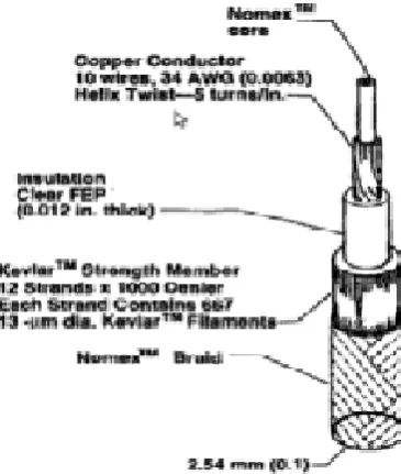
3.1.1. Electromagnetic Tether
Electromagnetic (EDTs) are long conducting wires, such as one deployed from a tether satellite which can
operate on electromagnetic principles as generators, by converting their kinetic energy to electrical energy, or
as motors, converting electrical energy to kinetic energy. Electric potential is generated across a conductive
315 | P a g e
Figure 1.Electro Dyamnic TetherTether Propulsion
As part of a tether propulsion system, crafts can use long, strong conductors (though not all tethers are
conductive) to change the orbits of spacecraft. It has the potential to make space travel significantly cheaper.
When direct current is applied to the tether, it exerts a Lorentz force against the magnetic field, and the tether
exerts a force on the vehicle. It can be used either to accelerate or brake an orbiting spacecraft.
The choice of the metal conductor to be used in an electrodynamic tether is determined by a variety of factors.
Primary factors usually include high electrical conductivity, and low density. Secondary factors, depending on
the application, include cost, strength, and melting point.
An electromotive force (EMF) is generated across a tether element as it moves relative to a magnetic field. The
force is given by Faraday's Law of Induction (Equation 1
Equation 1
Without loss of generality, it is assumed the tether system is in Earth orbit and it moves relative to Earth's
magnetic field. Similarly, if current flows in the tether element, a force can be generated in accordance with the
Lorentz force equation.
=
Equation 2
3.1.2. Combustion Chamber
It is a Chamber has Dimensions of 4x6x4 Ft and is made up of an Alloy of Tungsten and Molybdenum. In the
Ratio 25-75 % .The Alloy was chosen because it has a Melting Point (Depending On the %) It varies but is
always more than 2620 Celsius. So it can easily withstand the working temperature of Combustion Chamber is
316 | P a g e
3.1.3. Coolant SystemThe Coolant System is provided to the Combustion Chamber to avoid Heat Transfer. By reducing heat transfer,
we can improve the Efficiency by a Slight Value. The Coolant Circulated is Ammonia (NH3). Active thermal
control systems (ATCS) pump fluids through closed-loop pipes.
Because of ammonia's vaporization properties, it is a useful coolant. Anhydrous ammonia is widely used in
industrial refrigeration applications and hockey rinks because of its high energy efficiency and low cost. It
suffers from the disadvantage of toxicity, which restricts its domestic and small-scale use.
Ammonia coolant is also used in the S1 radiator aboard the International Space Station in two loops which are
used to regulate the internal temperature and enable temperature dependent experiments.
3.1.4. Cooling Chamber
The Cooling Chamber will be Approximately the same size of the combustion chamber. Made up o f
Aluminium. When helium is cooled below its critical temperature of 5.2 K to form a liquid. Even at absolute
zero (0K), helium does not condense to form a solid.
Advantage of gaseous Helium is its operation window: it can be used at any temperature between
ambient down to approx. 10 Kelvin. Restrictions that you mig ht have with other fluids like
liquefaction and or freezing are no issue with Helium gas. If the gas is pressurized sufficient density
is available for proper heat transfer.
3.1.5. Compression Chamber
The Compression Chamber is a Mechanical/ Hydraulic Press that crushes and compresses the Satellite. In such a
way it undergoes reduction of Mass and Volume. Like the Cooling Chamber it to is made up of Aluminium.
As it is Light in Weight.
3.2. Processes That Take Place in SDE-SAS-1
The Satellite is subjected to various processes to reduce its Mass and Volume as the Satellite is Non Functional
and No Longer of any use to its owner’s .The Components of the Satellite can be treated as Waste. So there is
no Pilfering on Satellite Components that is required. The Satellite is subjected to various Extreme Processes
that are sequentially named below;
Assimilation
Combustion (or) Melting
Rapid Cooling
Mechanical Compression
Ejection
317 | P a g e
3.2.1. AssimilationConductive tether whose area maximizes electrodynamic drag while simultaneously minimizing the
Area-Time-Product swept by the tether during its operating life. The preferred tether length is two kilometres to five
kilometres. The preferred tether mass is one per cent to five per cent of the spacecraft mass.
The same principles and concepts can be used to develop an electrodynamic net which would be a mesh of
aluminium and steel wires that hangs from an uncrewed spacecraft. The net is fitted with sensors that look for
light reflecting from small pieces of debris and automatically aligns itself so that it can attract the material. An
electrical current will flow through the wires, which creates an electromagnetic field reacting with the Earth’s
magnetic field that attracts the debris after which it will deposit the debris inside the uncrewed spacecraft
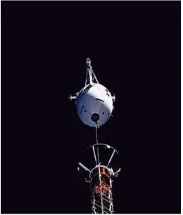
Figure 2 .Medium close-up view, captured with a 70mm camera,
Shows tethered satellite system deployment
3.2.2. Combustion and Melting
The Dead Satellite is subjected to a High Intensity Laser Beam where it is melted to a minimum so that it
undergoes a volume reduction.High average power lasers, e.g., free electron lasers (FELs) and solid-state lasers
(including fiber lasers) are prime candidates for efficient, directed energy applications. These include laser
power beaming and laser weapons, requiring multi-kWs of CW power operating in the IR regime.
High-intensity lasers operate in a different regime, e.g., peak powers of ∼1012–1015 W, pulse lengths of
∼10−12–10−14 s, intensities of ∼1014–1023 W/cm2, and repetition rates ranging from 103–106 Hz with average
318 | P a g e
Figure3. Diagram of Laser3.2.3. .Rapid Cooling
In This The Molten State The Satellite Is Moved Into The Cooling Chamber Via A Conveyer Belt. Where It Is
Subjected To A Coolant So That The Melt Is Frozen To Shape And Can BE Made Easily Feasible For
Mechanical Compression.
The Coolant can either be Ammonia (Liquid) or it can be Helium Gas. Depending upon Availability and
Economic Constrains. The Gas will be sprayed On the Melted Satellite So That It Undergoes Rapid Cooling and
becomes Brittle, thus can be easily compressed By Mechanical Compression. So In This Stage the Molten
Properties of Satellite materials (Table) Are Exploited.
3.2.4. Mechanical Compression
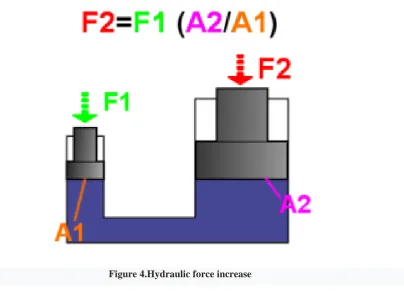
In This A Hydraulic Press (Figure) Is Used To Crush The Frozen- Melted Dead Satellite. The hydraulic press
depends on Pascal's principle: the pressure throughout a closed system is constant. One part of the system is
a piston acting as a pump, with modest mechanical force acting on a small cross-sectional area; the other part is
a piston with a larger area which generates a correspondingly large mechanical force. Only
small-diameter tubing (which more easily resists pressure) is needed if the pump is separated from the press cylinder.
Pascal's law: Pressure on a confined fluid is transmitted undiminished and acts with equal force on equal areas
and at 90 degrees to the container wall.
A fluid, such as oil, is displaced when either piston is pushed inward. Since the fluid is incompressible,
the volume that the small piston displaces is equal to the volume displaced by the large piston. This causes a
difference in the length of displacement, which is proportional to the ratio of areas of the heads of the pistons,
319 | P a g e
piston to move significantly. The distance the large piston will move is the distance that the small piston ismoved divided by the ratio of the areas of the heads of the pistons. This is how energy, in the form of work in
this case, is conserved and the law of conservation of energy is satisfied. Work is force applied over a distance,
and since the force is increased on the larger piston, the distance the force is applied over must be decreased.
Figure 4.Hydraulic force increase
IV. SOLUTION FOR MICRO SATELLITES AND LOWER SCALE
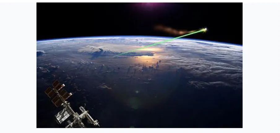
The laser broom (Figure) uses a ground-based laser to ablate the front of the debris, producing a rocket-like
thrust which slows the object. With continued application, the debris would fall enough to be influenced by
atmospheric drag. The momentum of the laser-beam photons could directly impart a thrust on the debris
sufficient to move small debris into new orbits out of the way of working satellites. NASA research in 2011
indicates that firing a laser beam at a piece of space junk could impart an impulse of 1 mm (0.039 in) per
second, and keeping the laser on the debris for a few hours per day could alter its course by 200 m (660 ft) per
day. The ablating material imparts a small thrust that lowers its orbital perigee into the upper atmosphere,
thereby increasing drag so that its remaining orbital life is short.[3] The laser would operate in pulsed mode to
avoid self-shielding of the target by the ablated plasma. The power levels of lasers in this concept are well
below the power levels in concepts for more rapidly effective anti-satellite weapons. Space debris is re-entered
regardless of the direction of laser illumination. Using a laser guide star and adaptive optics, a sufficiently large
320 | P a g e
Figure 5. Artistic representation of Laser BroomV. WHY VENUS FOR DUMPING THE COMPRESSED SPACE DEBRIS
Venus is a terrestrial planet and is sometimes called Earth's "sister planet" because of their similar size, mass,
proximity to the Sun, and bulk composition. It is radically different from Earth in other respects. It has the
densest atmosphere of the four terrestrial planets, consisting of more than 96% carbon dioxide. The atmospheric
pressure at the planet's surface is 92 times that of Earth, or roughly the pressure found 900 m (3,000 ft)
underwater on Earth. Venus is by far the hottest planet in the Solar System, with a mean surface temperature of
735 K (462 °C; 863 °F), even though Mercury is closer to the Sun.
Venus is shrouded by an opaque layer of highly reflective clouds of sulphuric acid, preventing its surface from
being seen from space in visible light. Thus Venus Was Chosen.
VI. CONCLUSION
Space debris has become the topic of great concern in recent years. Space debris creation can’t be stopped
completely, but it can be minimized by adopting some measures. Many methods of space debris mitigation have
been proposed earlier by many space experts, but some of them have limitations in them. After some
modification those measures can be proved beneficial in the process of space debris mitigation.
The Research Paper has reminded us about the Urgency to Deal with Space Debris, How Is It Harmful, What
Are is The Current Research going on, explained to us the Concept (SDE-SAS-1)and the Various Processes.
Also Has Given Us Something to Ponder About
We have already polluted our own planet earth; we should now ensure that the space is kept least polluted for
our own safe exploration of the outer space and also for the safety of aliens from other planets if they happen to
exist.
In this Project there is no loss of initial raw material like the Tether.
321 | P a g e
2. The Waste is Completely Demolished instead of storing it in graveyard zones / orbits unlike the solutionproposed by NASA.
3. One time Solution.
4. It requires only a one time investment of materials like Tether.
5. Diminish the chances of a catastrophic event like a Kessler’s Syndrome.
6. A Solution for both satellite ranges above 10 cm and Below 10 cm in Size.
7. Solar Panels will be used to power the system and the Shuttle.
We the Authors would like to conclude our Research Paper titled “SpaceDebris Eliminator-SAS-1” by
Reminding the Future Generation.
“Pessimism Can Never Lead To Innovation “
REFERENCES
Journal Papers:
[1]Phillip Sprangle and BahmanHafizi, High-power, high-intensity laser propagation and interactions.Physics
of Plasmas , Volume 2, Issue 5
[2] J. P. Longtin,C.-L. Tien,M. M. Kilgo &Russo. TEMPERATUREMEASUREMENT DURING
HIGH-INTENSITY LASER-LIQUID INTERACTIONS,A Journal ofThermal Energy Generation, Transport,
Storage, and Conversion, Volume 8, 1995 - Issue 4
BOOKS:
[1]George F Titterson, Aircraft Materials & Processes (Sterling Book House; India: Mumbai, 2007).
[2]William E Wiesel, Spaceflight Dynamics (Tata Mc Graw –Hill; India, 2007).
[3]F.C .Campbell,Manufacturing Technology For Aerospace Structural Materials (Elsevier; India, 2011)
WEBSITES
https://en.wikipedia.org/wiki
http://nerdist.com/360-degree-hydraulic-press-obliterates-all-objects-within-its-mighty-grasp/
https://www.rt.com/usa/333031-space-station-trash-ejection/
https://www.nasa.gov/mission_pages/station/news/orbital_debris.html
https://www.space.com/36602-space-junk-cleanup-concepts.html