A FRAMEWORK FOR
CONFERENCE CONTROL
FUNCTIONS
Nadia Kausar
A thesis submitted for the degree of
Doctor of Philosophy in Computer Science
University of London
June 2000
UCL
ProQuest Number: U643725
All rights reserved
INFORMATION TO ALL USERS
The quality of this reproduction is dependent upon the quality of the copy submitted.
In the unlikely event that the author did not send a complete manuscript and there are missing pages, these will be noted. Also, if material had to be removed,
a note will indicate the deletion.
uest.
ProQuest U643725
Published by ProQuest LLC(2016). Copyright of the Dissertation is held by the Author.
All rights reserved.
This work is protected against unauthorized copying under Title 17, United States Code. Microform Edition © ProQuest LLC.
ProQuest LLC
789 East Eisenhower Parkway P.O. Box 1346
Abstract
Conference control is an integral part in one-to-many communications that is used to manage and co-ordinate multiple users in different conferences. The degree which it controls the interaction of participants can vary in accordance with the conference structure in use. Conferences come in different shapes and formats but in recent years the two different views of conference control has been realised by two prominent standard bodies: International Telecommunication Union (TTU) and the Internet Engineering task Force (IETF). The former has focused on the centralised control of conferences (formal/tightly coupled). Whereas the IETF approach is referred as the informal/loosely coupled conference. However, in addition there are other conference controls for desktop multimedia system that are not yet standardised.
In this thesis the writer proposes a generic conference control system to provide a single mechanism that supports interoperability between two or more inherently different architectures mentioned above. The consequence of having very distinctive systems is that they are not interoperable. Each system provides a set of functionalities that are not easily provided in the other one. Users or administrators of such systems end up supporting dual stack technologies. However, both the systems have some common components like a call control and media part. In this research, one of the key tasks performed was to interwork two innate different architectures using their common call control functions. Also, a set of conference control functions have been derived and implemented that can be used by any conferencing systems over heterogeneous networks. The architecture that provides a set of functions and requirements that are visible or invisible to any user in any type of conferencing is termed as CCCS (Common Conference Control services) in this thesis.
In order to evaluate the integration of different services offered by different conference control model, lETF’s Session Initiation Protocol (SIP) and ITU’s H323 conferencing have been interoperated in an implementation. It has been established that conferees from completely different architectures can participate in one session by a mechanism such as CCCS which interoperates a set of services that are common in any conferencing systems. These common services have been derived by careful analysis, and with the aid of formal methods, state transition diagrams and a well- known software design pattern. The CCCS framework presented in this thesis provides the flexibility to users which are not present in just one of the architectures alone.
Acknowledgements
This thesis is the result of persistence, determination, and hard work. The four years that went in to
produce this work received a lot of support from friends, family and UCL’s members of staff. Without
them I do not believe that I could have completed this work.
First of all, I would like to thank my supervisor Jon Crowcroft for the discussions and the idea
exchanges that formed the backbone of this thesis. My UCL friends, Steve Wilbur, Graham Knight
and the Networked multimedia team provided tremendous constructive criticism that earn my sincere
gratitude. Ken Carlberg deserves very special thanks for believing in me and for being there when I
needed help the most. Furthermore, I would like to thank Ian Marshall in BT labs for inspiring me with
VoIP ideas and funding me for three years.
I would also like to thank my friends outside UCL (who managed to stay as friends after all these years
of me ignoring them because of this PhD) and William Fahy for being supportive. My loving family
always helped me with moral support and they always thought I could finish this PhD. Unfortunately
my dearest father did not see my hardest effort come to an end. I dedicate this thesis to the loving
TABLE OF CONTENTS
CHAPTER 1
Introduction 1
1.1 Group cooperation and different phases 4
1.2 Conference parameters and components 5
1.3 Conference Control Requirements and different perspectives 7
1.4 Objectives and thesis statement 13
1.5 Thesis Outline 14
CHAPTER 2 17
Related Work 17
2.1 The ITU architecture for multimedia conferencing 18
2.1.1 T.120 recommendations 19
2.1.1.1 Different components of T. 120 based conferencing 20
• Generic Conference Control (GCC) 21
• T. 124 Revised 22
2.1.1.2 Sequence of actions in T. 120 based conferencing 23
2.1.2 H.323 conferencing 24
2.1.2.1 Scope of H.323 25
2.1.2.2 Sequence of operations in H.323 based conferencing 27
2.1.2.3 Netmeeting - A product based on H.323 28
2.1.3 H.Loosely Based Conferencing 29
2.2 The IETF architecture for multimedia conferencing 30
2.2.1 IETF’s basic requirements and design 31
2.3 Different protocols 32
2.3.1 Mbone 32
2.3.2 Session Directory Protocol (SDP) 33
2.3.3 Session Announcement Protocol (SAP) 34
2.3.4 Session Initiation Protocol (SIP) 35
2.5 Other conferencing systems 37
2.5.1 The CAR conferencing systems 37
2.5.2 The LAKES architecture 38
2.6 Conference Controls 39
2.6.1 MMCC 41
2.6.2 CCCP 42
2.6.2 CONFCNTLR 43
2.6.3 SCCP 43
2.6.4 Confman 45
2.7 Gateways 47
2.7.1 H.323 and SS7ISUP Gateway 47
2.7.2 Simple Gateway Control Protocol (SGCP) 48
2.8 Conclusion 49
CHAPTER 3 51
Common Conference Control Services (CCCS) 51
3.1 The Basis of Group Communication: A conference protocol stack 52
3.1.1 Components of the architecture 53
3.1.2 Conference administration services 54
3.2 CCCS’s user visible services 56
3.3.1 Design model of the CCCS’s Interoperability functions 60
3.3.2 Main operation of the CCCS 62
3.3.3 The CCCS’s interoperability services 65
3.3.4 Main conference control contrast between H.323 and SIP 66
3.3.5 Basic Call set-up between H.323 and SIP 68
3.4 GS message format 70
3.5 Performance measures 72
3.6 Error control 75
3.7 Transport services 76
3.8 Intelligent Network operations 77
3.8.1 Service features 77
3.9 Conclusion 79
CHAPTER 4 81
Background of Reliable IP Multicast 81
4.1 Background of IP Multicast 82
4.2 Approaches for reliable data delivery 83
4.3 Design issues of reliable multicast 85
4.3.1 Organisation of nodes in a reliable multicast 85
4.3.2 Soft State vs Hard State 86
4.4 Protocols 88
4.4.1 Multicast Transport Protocol [MTP] 88
4.4.2 Multicast Transport Protocol -2 [MTP-2/ MTP/SO] 90
4.4.3 Scalable Reliable Multicast [SRM] 91
4.4.4 Reliable Multicast Transport Protocol [RMTP] 92
4.4.5 Reliable Multicast data Distribution Protocol [RMDP] and Reliable Layered Congestion
control [RLC] 94
4.4.6 Pragmatic General Multicast [PGM] 96
4.4.7 Example of reliable multicast embedded application; Network Text Editor [NTE] 98
4.5 Conclusion 100
CHAPTERS 101
Reliable IP Multicast Transport Protocol Requirements for Conference Control 101
5.1 Problem scenario 101
5.2 Key Design Issues in IP multicast Transport Protocols 103
5.3 Floor control and its requirements 104
5.3.1 Functional Criteria 106
5.4 Analysis of available reliable IP multicast - limitations, advantages and disadvantages 107
5.5 Limitations of floor control 109
5.6 Proposed solution 111
5.7 Conclusion 116
CHAPTER 6 117
A charging model for Sessions on the Internet 117
6.1 Problem Scenario 118
6.2 Review of basis for charging in the network 120
6.3 Entities that bundle services 124
6.3.1 Matrix for charging sessions on the Internet 127
6.4 Model for application driven session pricing 129
6.4.1 Support from Network layer 131
6.5 ISP’s perspective
6.6 Multicast Model
6.8 Conclusion
CHAPTER? ‘•^0
LIST OF FIGURES
FIGURE 1: THE FOUR PHASES OF GROUP COLLABORATION__________________________ 4
FIGURE 2 MEETING TYPES [SOURCE: SCHOOLER [SCHOOLER93]]... 6
FIGURE 3: ACTIVITIES IN A CANONICAL CONFERENCE_____________________________ 12
FIGURE 4: T.120 RECOMMENDATION INFRASTRUCTURE_____________________________ 20
FIGURE 5: HIERARCHY STRUCTURE OF T.120 NODES CONNECTING UP TO A SINGLE M C U ...21
FIGURE 6: ENVIRONMENT OF H J23 AND SAMPLE NETWORK TOPOLOGY____________ 25
FIGURE 7: CONFERENCE STACK FOR H.323...26
FIGURES: MESSAGE SEQUENCE IN A H.323 BASED CONFERENCING_________________28
FIGURE 9: A LARGE CONFERENCE CONSISTING OF AN H 323 PANEL AND RTP/RTCP BASED RECEIVERS... 29
FIGURE 10: ANNOTATED SDP SESSION DESCRIPTION_________________________________ 33
FIGURE 11: SIP REQUEST BEING RELAYED___________________________________________ 35
FIGURE 12: INTERNET CONFERENCING PROTOCOL STACK... 37
FIGURE 13: COORDINATED MANAGEMENT OF SEPARATE SERVICES_________________41
FIGURE 14: CONFMAN RUNNING IN A WWW SERVER________________________________ 46
FIGURE 15: CONFERENCE PROTOCOL STACK________________________________________53
FIGURE 16: COMPONENTS FOR CONFERENCE MANAGEMENT SERVICES_____________ 55
FIGURE 17: RESPONSIBILITY AND COLLABORATORS OF A BROKER... 61
FIGURE 18: OBJECTS INVOLVED IN A BROKER SYSTEM______________________________62
FIGURE 20: TOPOLOGY OF THREE DIFFERENT TYPES ARCHITECTURES
INTEROPERATING USING CCCS...65
FIGURE 21: MESSAGES EXCHANGED BETWEEN H.323 AND SIP FOR “INVITE” _________69
FIGURE 22: MESSAGES EXCHANGED BETWEEN SIP AND H.323_______________________ 70
FIGURE 23: A SIMPLE EXAMPLE OF INTEROPERATION BETWEEN A SIP CLIENT, A H.323 CLIENT AND GS CLIENT... 72
FIGURE 24: AVERAGE MESSAGES PASSED BETWEEN H 323 AND SIP TERMINALS_____ 74
FIGURE 25: METHODS OF FORWARDING AND RECEIVING PACKETS IN CCCS________ 76
FIGURE 26A: A BASIC DIAGRAM OF A SENDER INITIATED PROTOCOL... 84
FIGURE 27: A DISTRIBUTED MODEL OF RELIABLE MULTICAST PROTOCOL_________ 86
FIGURE 28: A BASIC DIAGRAM OF A TREE BASED RELIABLE MULTICAST PROTOCOL 86
FIGURE 29: A BASIC DIAGRAM FOR PGM.____________________________________________ 97
FIGURE 30: TREE STRUCTURE FOR HIERARCHICAL TRANSPORT PROTOCOL_______ 113
FIGURE 31: BUNDLING SERVICES... 124
FIGURE 32: MODEL OF INTERACTION BETWEEN PARTICIPANTS AND AGENCY_____ 128
FIGURE 33: AN EXAMPLE OF FRONT END OF PAYMENT SERVICE... 130
FIGURE 34: SESSION DIRECTORY WOULD NEED AN OPTION FOR PAYMENT________ 131
FIGURE 35: RELATIVE TRAFFIC ELASTICITY... 131
FIGURE 36: PDU FOR RESOURCE RESERVATIONS ENHANCED BY CHARGING AND ACCOUNTING DATA... 134
FIGURE 37: CONFERENCE CONTROL AND SESSION BASED CHARGING WITH RSVP... 135
LIST OF TABLES
Table 1: Human level of conference control...9
Table 2: Application level of conference control... 10
Table 3: Network level of conference control...11
Table 4: Summary of user-visible services of a conference control[Ott J ] ... 57
Table 5: Number of messages transferred interconnecting SIP and H.323 using CCCS... . . .... .. 73
Table 6: Number of messages transferred and time taken between two H.323 terminal and two SIP terminals without a gateway...73
Table 7: Comparison of multicast transport protocols for floor control...___ ... 106
Chapter 1
Introduction
This thesis presents a new framework for multimedia conferencing systems. The recent advances in computer technology and data networking have made video conferencing a popular medium for users to interact with each other from remote locations. The term “conferencing” is used in two different ways: firstly to refer to bulletin boards and mail list style asynchronous exchanges of messages between multiple users; secondly, to refer to synchronous or real-time conferencing including audio, video, shared whiteboards and other applications [Schooler93]. This thesis focuses on the architecture and the functionality required for the latter application and the former one will be ignored from now on.
Conferencing
Asynchronous Synchronous
Loosely coupled Tightly coupled Conference control Conference control
International Telecommunication Union (ITU) and the Internet Engineering Task force (IETF).
The underlying architecture o f these two types o f conference is inherently different. The IETF model uses a distributed approach where no chairman role for a conference is necessary. The senders are not aware o f all the receivers, so this type o f conferencing can scale to a large number o f participants. The ITU’s model o f tightly coupled conferencing is designed mainly for the circuit switched networks and different channels are used for the chairman role and the media distribution. The knowledge o f all participants and the applications involved are necessary in this model. The consequence o f having these two distinctive systems is that they are not easily interoperable. As a result users end up supporting several tools and multiple protocol stacks because the nature o f a particular type o f conference may change or the users may decide to use a different set o f tools half way through a conference. For example, three participants in a research conference may decide that the conference they are currently holding should really be a brainstorming session and a lot more people are need to be involved. At present, it is very difficult to change from a tightly coupled conferencing scenario to loosely coupled and vice versa. Also it is difficult to manage and maintain various applications and operating systems associated with extremely different models and the difficulty o f changing from one system to the other shows the inflexibility o f today’s conferencing model.
and minimum required resources to join a conference. But, there is little information available on the full architecture o f different models o f conference control and its management. A “common control” architecture will provide essential features and systems based on that will be easy to design, implement and maintain. The users then do not have to maintain multiple stack technologies in order to switch from one model to the other.
The purpose o f this thesis is to examine how communication using different conference control mechanisms can be seamlessly integrated into a single mechanism, and to propose the Common Conference Control Services (CCCS) that provides a set o f functions and services in a framework that is essential for any conferencing system. The aim to develop a communication infrastructure rather than a specific groupware application has several implications. First o f all, no assumptions about the environment can be made [Ott J]. The infrastructure has to be portable across different hardware and operating systems platforms and has to provide the foundation necessary to achieve interoperability between different conferencing systems. Therefore, we propose a system that operates on the session layer. The other advantages o f a session layer based protocols are : a) it is transparent to network support b) it has minimum impact on applications, and c) the design is extensible. As an example o f extensibility, the design of the CCCS is able to support additional functionalities that are not directly applicable, such as charging [Kausar (c)].
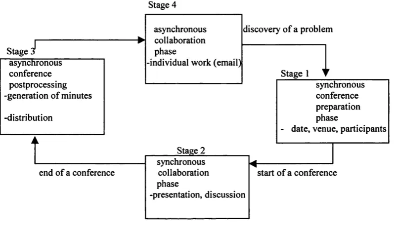
1.1 Group cooperation and different phases
Specific types o f group cooperation can be decomposed into asynchronous collaboration, followed by a synchronous collaboration phase as shown in Figure 1.
Stage 3
asynchronous conference postprocessing -generation of minutes
-distribution
end of a conference
Stage 4
asynchronous collaboration phase
-individual work (email)
discovery o f a problem
Stage 1
synchronous conference preparation phase
- date, venue, participants
Stage 2 synchronous collaboration phase
-presentation, discussion
start of a conference
Figure 1 : The four phases of group collaboration
Synchronous interaction requires the presence o f all cooperating users while asynchronous cooperation occurs over a longer time period and does not require the simultaneous interaction o f all users [Rodden]. In this thesis we concentrate on the synchronous collaboration phase (stage 2). This phase covers the entire course o f a conference with two or more participants. A conference may include presentations, discussions, reviews, voting, cooperating work sessions (e.g joint editing etc.). Due to the immediate interactions, the synchronous collaboration phase is also best-suited for updating group members about the latest developments, current project status, etc. Therefore, this cooperation phase is crucial to the entire process o f group collaboration.
In reality, the borders between the phases are soft: individual phases may overlap with others. Depending on the situations, phases may also be very short or even left out entirely.
The next section gives an overview o f conferencing and discusses different conference parameters and components and their positions in different layers o f OSI.
1.2 Conference parameters and components
Figure 2 shows different meeting types that present the type o f conference on the left hand side, a simplified correlation with meeting types, a set o f meeting parameters [Schooler92] like interactivity between participants, and the number o f participants that may be involved. These parameters and components make up a canonical model o f conferencing which is the guideline for designing either a distributed or a centralised model o f conferencing (discussed further in section 1.3).
In the following, a set o f parameters that are shown in Figure 2 are discussed. These parameters may be used to describe the characteristics o f all meeting types [Schooler92]: • Interactivity - Traditionally, a highly interactive conference tends to be a telephone
call, or a hallway meeting where number o f participants is low and it has high coordination.
• Group size - Ranges from two to more than a million (TV broadcast), for most review type o f meetings or small panel discussions, groups o f up to twenty are common. • Conference duration - Ranges from minutes to hours.
• Geographic distribution - participants could be located on the same floor, in the same building, conference room or different countries.
• Establishment - conferences can be established in an ad-hoc manner or in advance, it may start at a planned time or it may start when the invitee has joined the phone call. Big conferences like seminars are normally planned in advance whereas telephone calls take place in an ad hoc manner.
Floor control -Floor control, a metaphor for "assigning the floor to a speaker", which is applicable to any kind o f sharable resource within conferencing and collaboration environments. The tighter the floor control is, the conference type is classified more as a formal conference or tightly coupled conference.
Meeting type Main characteristics Interactivity no o f Participants'
Point-to-point call
Hallway meeting
Review meeting
(e.g. boardroom meeting)
Classroom
Panel discussion
Seminar
Lecture
TV broadcast
high coordination high
rigid
small sessions high
static high
low
few policies low
low overhead
Large sessions
dynamic (receivers change)
2-6
2-20
less coordination medium-low 10-100
10-100s
1 Os-1000s
Figure 2 Meeting Types [Source: Schooler [Schooler93]]
• Conference policy - A conference policy describes how strictly a conference is managed and issues o f conductorship (as described below) and privacy issues. User characteristics influence a policy, for example, a policy might be user-dependant and role dependant. A chairperson role might allow a single person to mediate floor control decisions, or priorities associated with users might help resolve conflicting
requests for control. A policy might implement a single global thread o f control for a whole application, or it might provide independent control over individual parts o f an application (i.e. objects) [Boyd]. A conference architecture has to accommodate both extremes as far as these policies can be actively supported by technology [Boyd]. Privacy policies control whether other clients can learn o f the sessions existence, its attributes and the identities o f the current session participants.
• Conduct management - A conference may be chaired by a participant (the chair person may be prearranged) or the conductor role may be passed around. A conference may also switch between conducted and non conducted mode depending on the task being performed.
• Coupling mode - Coupling mode refers to the consistency o f state information about a teleconference at the various participating sites. In a tightly coupled scenario, all participants are aware o f the participant list, their roles, what applications are there and why and how they are being used, e.g. a small meeting room. In a loosely coupled scenario, consistency is not explicitly provided for. Participant lists are not exactly known, all the applications may not be used by everyone at every site. An example o f this could be a talk with an audience o f hundreds o f listeners.
The next section is a detailed overview o f conference control and its association with different levels.
1.3 Conference Control Requirements and different perspectives
Most o f the conferencing models need to fulfil some basic system requirements:
a) Application interaction - Applications for multimedia conferencing, e.g. video tool, whiteboard etc. need to be started with the correct initial state, and the knowledge o f their existence must be propagated across all participating sites. Applications may need to cooperate (for example to achieve audio and video synchronisation)
b) Membership control - Who is currently in the conference ? [Handley]
d) Network Management - Request to set up the connections between end-points and request from the network to change bandwidth usage.
e) Session management - Startup and Finish Conference, inviting people, joining, side sessions etc.
t) Ordering - Process ordering and ordering o f the resource requests, so avoid all necessary deadlock situations,
g) Reliability - Sending applications need to be sure that the destinations received the messages. Whether all the messages sent out have to be acknowledged or the n out o f
m destinations picked up the message is a design issue within the conference control.
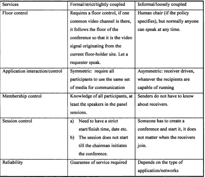
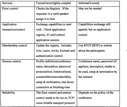
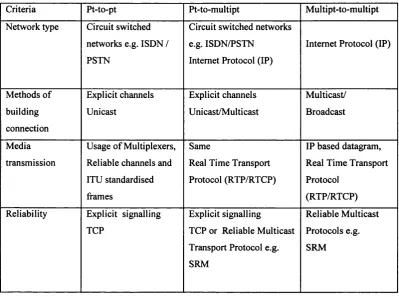
Depending on users’ activities in different styles o f conferencing, the services expected from conference control vary from application level to network level. So for example, in a tightly coupled conferencing membership control and its consistency are very critical to the user in the application layer. The network should be reliable to support this activity but it is not up to the network to provide that information. On the other hand, in a loosely coupled conferencing, the network must be able to handle a large number o f participants. In this framework consistency arises slowly by virtue o f the periodic updates sent by network nodes (details in Chapter 4). Table 1, 2 and 3 outline the different services provided by conference control at user, application and network level.
Services Formal/strict/tightly coupled Informal/loosely coupled
Floor control Requires a floor control, if one
common video channel is there,
it follows the floor of the
conference so that it is the video
signal originating from the
current floor-holder site. Let a
requester speak.
Human chair (if the policy
specifies), but normally anyone
can speak at any time.
Application interaction/control Symmetric: require all
participants to use the same set
of media for communication
Asymmetric: receiver driven,
whatever the recipients are
capable o f running
Membership control Knowledge of all participants, at
least the speakers in the panel
sessions.
Senders do not have to know
about receivers.
Session control a) Need to have a strict
start/finish time, date etc.
b) The session does not start
till the chairman initiates
the conference.
Someone has to create a
conference and start it, it does
not matter when the receivers
join.
Reliability Guarantee of service required Depends on the type of
appl ication/networks
Table 1: Human level o f conference control
Services Formal/strict/tightly-coupled Informal/Loosely
Floor control Checks the Registry, If the
requester is a valid speaker
assign it to him.
May not be needed
Application
Interacti on/control
Exchange capabilities to start
with. Check application
registry, If valid control
application session.
Capabilities exchange still
applies, but no application
control.
Membership control Update the registry. Includes
Join, Leave, Invite, Exclude and
authentication control.
Use RTCP [RTP] to inform
about the participants
Session control Profile defmition(conference
name, description, password
protected/not, listed/unlisted,
conductible/nonconductible),
setup & termination, tear down
connection at finishing time
Conference name, password (if
applies), description, media to
be used, setup & termination by
the initiator
Reliability The floor control and session
control needs to be run on TCP/
some reliable transport protocol
Depends on the policy o f the
conference
Table 2: Application level of conference control
Criteria Pt-to-pt Pt-to-multipt Multipt-to-multipt
Network type Circuit switched
networks e.g, ISDN /
PSTN
Circuit switched networks
e.g. ISDN/PSTN
Internet Protocol (IP)
Internet Protocol (IP)
Methods of building connection Explicit channels Unicast Explicit channels Unicast/Multicast Multicast/ Broadcast Media transmission
Usage of Multiplexers,
Reliable channels and
ITU standardised
frames
Same
Real Time Transport
Protocol (RTP/RTCP)
IP based datagram.
Real Time Transport
Protocol
(RTP/RTCP)
Reliability Explicit signalling
TCP
Explicit signalling
TCP or Reliable Multicast
Transport Protocol e.g.
SRM
Reliable Multicast
Protocols e.g.
SRM
Table 3: Network level of conference control
In order to conduct a point-to-point or point-to-multipoint conference, we need to create certain types o f channels which convey the services. The conferences based on Circuit Switched networks have separate channels for call connection/control and media transmission. For example, for two people to exchange audio, two logical channels must be opened, one from caller to callee, and vice versa. Also in order to carry media, two different channels must be opened from both sides. This is done to ensure reliable delivery of media.
looks like. A typical desktop conferencing always shows certain activities as seen in Figure 3.
Conference creation (assignment of a conference ID)
Advertise the conference Invite participant
i
i
Participant chooses to enter conference Invitee is notified
--- 1--- ► Reject invitation
Admission control (negotiate capabilities/codecs etc.)
Join conference (if password is needed, provide it)
Media flow (if different media then media gateway is used)
t
Floor control (send media if the current participant is the floor holder)
End o f a conference / participants leave
i
Tear down connection
Figure 3: Activities in a canonical conference
the requestor gets to speak or transmit data and this process is fair (i.e. consistent with the conference policy). The minimum quality that is expected from a conference is the reliable delivery o f data. After the conference terminates, the appropriate channels for media or signalling are successfully closed down.
Observation shows a canonical model o f conferencing tends to follow a pattern which is described above, which proposes that the minimum number o f essential activities that a control mechanism needs to cater for are:
• Creation o f a conference • Facilities to join a conference • Invite a participant
• Floor control • Reliability
• Leave a conference
Most o f the activities shown in Figure 3 are supported in CCCS proposed in this thesis.
1.4 Thesis statement and objectives
The main objective o f this thesis is to present a generic framework for multimedia
conferencing.
To identify and observe different coordination and control tasks
associated with separate conferencing model and propose an ideal way to integrate and
support these tasks. Identify parts in specific architecture where components are missing
and where components that can be unified easily.
This research work sets out to propose a framework. Common Conference Control Services (CCCS) to show that it is possible to develop a generic framework for conference control and conferencing. During the research a number o f sub-objectives became clear which makes this framework more effective:
• Transport protocol • Reliability
CCCS framework has been designed to be extensible. In the future when there will be a requirement to add billing and authentication services as an integral part o f commercial conferencing, CCCS is flexible enough to cater for that. The architectures we have today for conferencing do not support additional services to be added in the easiest manner. In this thesis a new charging mechanism is proposed as a value added service for conference control which can be integrated in the proposed framework.
The framework proposed needs to support major existing conferencing architectures from networks perspective to be effective. A network needs to assist the CCCS to provide its main ser\dces reliably in a scalable manner. Reliable data delivery for conferencing control functions in a heterogeneous environment like the Internet model has not been investigated and lacks a solution. A suitable transport protocol has been proposed that will provide the requirements o f conference control, like congestion control, membership control and reliability over the Internet.
Finally, an implementation needs to be carried out to validate the concept o f interoperability o f different conferencing models.
1.5 Thesis Outline
In Chapter 2, related work is discussed, mainly giving an overview o f IETF and ITU models o f conferencing; its design, architecture and distinctive models o f conference control associated with these architectures are also reviewed. A summary o f both models o f conferencing is provided at the end o f the chapter. We did not consider it appropriate to provide an extensive overview o f much earlier work that assisted in the evolution o f the conferencing frameworks we have today, since this is covered elsewhere [Boyd]. However, we will mention early work where we consider it relevant.
generic framework for conference control referred as CCCS, that can provide that functionality will be introduced in Chapter 3. In this chapter, two main features o f conference control protocol are identified and a framework in that reference is developed. A framework that can interoperate between two innately different models o f conferencing has been implemented as a proof o f concept. Implementation details such as message format, transport services, error control and performance is also discussed here.
In Chapter 4, reliable network protocols, especially reliable IP multicast protocols are reviewed. A generic framework for conference control such as CCCS needs to provide its services reliably. Therefore, a reliable network is required to support this framework to be effective. The conferencing architectures seen in ITU today provide reliability but not scalability, whereas in the IETF model o f conferencing we experience the contrary. Therefore, a network protocol that can support a large number o f participants but be reliable at the same time is vital. Reliable IP multicast introduced in 1990 [Deering] shows a promising solution for future conferencing and therefore in this chapter we introduce some o f the available protocols.
In Chapter 5, some o f the reliable multicast transport protocols described in Chapter 4 are analysed for the purpose o f conference control. In other words, most suitable features and functionality provided by reliable IP multicast protocols for some crucial features o f conference control are identified. We do not propose a new network protocol but propose some adaptations to the most suitable existing network protocol.
Chapter 2
Related Work
This thesis and the related work that we discuss here, concentrates on different models o f conferencing, its structure and requirements. In this chapter in particular we discuss design, implementation and requirements o f conferencing in Application and Session layer. We do not discuss network or transport layer requirements in details here.
Computer based, desktop conferencing systems help people to interact with each other from their homes or offices by exchanging information in several media. These systems support real-time conversation through the co-ordinated exchange o f voice, video, and computer program output (e.g., text, graphics, and spreadsheets) [Ahuja]. Conference participants can share multimedia information, simultaneously view and update information if required. The participants can be close to one another, exchanging information over a local area network (LAN), or geographically separated, transmitting information over wide area networks (WANs). A common goal o f these conferencing systems is to emulate important characteristics o f face-to-face conversations. The catch with personalizable conferencing is that it is difficult, if not impossible, for designers to predict ahead o f time the complete range o f behaviours the system should exhibit. One solution is to make the system flexible, so that new behaviours can be created and old ones modified in ways that the original designer had not anticipated.
conference policy or at least to inform the crowd o f who is present. In addition, security measures and interoperability may be required to enforce the conference policy.
In this chapter, we review how conferencing architectures have developed and evolved to meet the above mentioned criteria. We primarily focus on the circuit switched ITU and the packet switched IETF model o f conferencing, since these two models o f conferencing dominate the research community and the commercial industry. In the process, the shortcomings and the strengths o f both models are pointed out. Then we focus on other conferencing architectures and conference control protocols that have been researched and implemented. Finally we look at some gateway protocols that are currently being analysed and implemented as a result o f a dramatic change in telecommunication industry. The most significant change in the last twenty years has been the move from using circuit switched networks for multimedia data towards packet-switched networks and the Internet in particular for multimedia data [Handley M]. More recently, ITU’s original design o f conferencing has evolved to include packet networks, and a more loosely coupled and distributed approach to conference control.
2.1 The ITU architecture for multimedia conferencing
The design o f ITU’s conferencing and the controls associated with it originated in person-person video telephony, across the POTS (Plain Old Telephone System) or its digital successor, ISDN. This is a circuit model, where one places a call using a signalling protocol with several stages and the link resources are allocated at the call setup. The resources such as communication channels are released at the end o f a call. The general assumption is that all participants are consistent about the status o f other participants, applications and applications’ capabilities.
The low level protocols have been primarily designed for point-to-point audiovisual communication, in particular video telephony. They define the communication procedure for placing a multimedia call between two systems which are network dependant. The low level protocols which are network specific are developed by Study Group 15 o f the ITU^ and are defined in several series o f recommendations:
• The H.310 series o f recommendation for ATM networks, • The H.320 series o f recommendations for ISDN
• The H.321 recommendation for use o f H.320 on top o f ATM
• The H.323 series o f recommendations for corporate (inter) networks, and
• The H.324 series o f recommendation for analogue telephone networks and mobile systems.
Along with the definitions o f the system components, system operation, and communication procedure, a set o f audio and video encoding recommendations has been defined^. Wenger [Wenger95] discusses various encoding schemes and especially the H.320 series o f recommendations.
2.1.1 T.120 recommendations
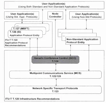
The high level conferencing infrastructure for ITU is described in the T.120 series o f recommendations. Its development started around 1990 with the first recommendation o f the series being approved by the ITU in 1993. At the time o f writing, ten recommendations have been approved that define multipoint communication and conference control functionality as well as application protocols. The T.120 model is composed o f a communications infrastructure and application protocols that make use o f it. The ITU Secretariat maintains a list o f the currently valid ITU Recommendations
^The work started in the late 1980s for video telephony over ISDN
(T. 121 - T. 127). Each layer provides services to the layer above and communicates to its peer(s) by sending Protocol Data Units (PDU) via services provided by the layer below.
User Application(s)
(U sing Both S ta n d a rd an d N o n -S tan d ard A pplication P ro to co ls)
User Application(s) (U sing Std. Appl. P rotocols)
Node Controller
f
T.127 (MBFT) T.126 (SI)A p p lic a tio n P ro to c o l E n tity
IT U -T T .1 2 0
A p p lic a tio n P ro to c o l R e c o m m e n d a tio n s
User Application(s) (U sing N on-S td P ro to co ls)
Non-Standard Application Protocol Entity
Generic Conference Control (GOG) T.124
Multipoint Com munications Service (MCS) T.122/125
Network Specific Transport Protocols T.123
ITU-T T.120 Infrastructure Recommendations
Figure 4: T.120 recommendation infrastructure
2.1.1.1 Different components of T.120 based conferencing
Node 1
Node Controller
T op GOG Provider
M C S Connections
Node 2 Node 3 Node 4
GCC Provider
GCC Provider
G CC Provider
\pplicatloi Protocol
s ^ t i t ^
(pplicatioi Protocol
s J n t i t y ^
Node Controller
Node Controller
Node Controller
Figure 5: Hierarchy structure ofT .120 nodes connecting up to a single MCU
As it can be seen from the above diagram, each domain has a single Top Provider or MCU (marked as Node 1) that houses the state information o f all other nodes in the domain and is critical to the conference. If the Top Provider either fails or leaves a conference, the conference is terminated. If a lower level MCU (i.e., not the Top Provider) fails, only the nodes on the tree below that MCU are dropped from the conference.
• Generic Conference Control (GCC)
T.124 Generic Conference Control provides a comprehensive set o f facilities for establishing and managing the multipoint conference. It is with GCC that we first see features that are specific to the electronic conference. At the heart of GCC is an
important information base about the state of the various conferences it is servicing. One node, which may be the MCU itself, serves as the Top Provider for GCC information. Any actions or requests from lower GCC nodes ultimately filter up to this Top Provider.
GCC is updated and can be used to automatically notify all endpoints when these actions occur. GCC also knows who is the Top Provider for the conference. However, GCC does not contain detailed topology information about the means by which nodes from lower branches are connected to the conference.
Every application in a conference must register its own application ID with GCC. This enables any subsequent joining nodes to find compatible applications. Furthermore, GCC provides robust facilities for applications to exchange capabilities and arbitrate feature sets. In this way, applications from different vendors can readily establish whether or not they can interoperate and at what feature level. GCC also provides conference security. This allows applications to incorporate password protection or "lock" facilities to prevent uninvited users from joining a conference.
Another key function o f GCC is its ability to prevent conflicts for resources such as tokens and channels. Its ability to manage shared resources ensures that applications do not step on each other by attaching to the same channel or requesting a token (such as floor holder token) already in use by another application. Finally, GCC provides capabilities for supporting the concept o f strict floor control in a conference. GCC allows the application to identify the floor controller and a means in which to transfer the holder’s token.
The design and the structure o f T.120 based conferencing imply that when the number o f clients and applications increase, the size o f GCC’s register containing information o f capabilities and various features o f clients grow with it. The Top Provider becomes a bottleneck and the performance o f the MCU decreases. In order to address some o f these problems, T.124 has been revised.
• T.124 Revised
all nodes participating in a conference any time a node joins or leaves a conference. This registry contains detailed information on applications, other nodes’ capabilities and their details.
To improve the distribution o f roster information, the concept o f Node Categories was introduced. These categories provide a way for a T.124 node to join or leave a conference without affecting the roster information that was distributed throughout a conference. In addition, the Full Roster Refresh, which was previously sent any time a new node joined a conference, was eliminated by sending out roster details from the Top Provider. These changes will not affect backward compatibility to earlier revisions o f T.124.
2.1.1.2 Sequence of actions in T.120 based conferencing
The pattern o f a T.120 based conference is: a) Create the conference
b) Invite a participant to the conference
c) The participant accepts and joins the conference d) Update the roster/application/membership registry e) Terminate the conference
2.1.2 H.323 conferencing
H.323 [H.323] is an umbrella recommendation from the ITU which is designed to extend traditionally circuit based audio visual and multimedia conferencing services into packet (i.e. IP-based) networks. The H.323 system aggregates a number o f standards, which together allow establishing and controlling point-to-point calls as well as multipoint conferencing. It provides a tightly controlled communication model, with explicit control and media connections set up between participants.
Although H.323 is minimally defined to operate utilising only peer H.323 terminals, the recommendation defines a number of additional logical H.323 elements. These elements are: terminals, gatekeepers, gateways, and multipoint control units (MCUs). Their main functions are:
• Terminal- clients/endpoints that provide two-way communication
• Gateway- an optional element to provide interoperability (H.320 compliant terminals over (ISDN, H.324 over PSTN)
• Gatekeeper - performs a number o f tasks: address translation, bandwidth management, and charging for calls.
• Address translation - gatekeeper acts as a central point for a H.323 zone address translation from LAN aliases to IP or IPX.
• Bandwidth management - it is up to the gatekeeper to ensure that calls made to H.323 terminals via a gatekeeper have enough bandwidth to complete the call.
• Charging - work is currently in progress [Gary] to allow calls to be routed to the gatekeeper so that they can be charged.
• MCU- supports conferences between three or more terminals, mainly consists o f MC (multipoint controller) and MP (multipoint processor). MC handles capability negotiations and MP deals with media streams like media mixing, switching
Although H.323 clearly defines services and interactions between all of these logical elements, there are no specific hardware or software requirements mandated. Figure 6 depicts an environment of H.323 in terms of the logical system components and also shows a sample network topology which interoperates with the circuit switched networks (ISDN, PSTN) based conferencing
H .3 2 3 C o n fe r e n c in g A r c h ite c tu r e
H 323 terminal H H .323 M CU
%
Puoke l Buse d Ne tw ork
Galway”
G a te k e e p e r
^ Switched ciratit 0 (IS D N )
:\fs §--- Networks
- S p e e c h O n ly
Internet H .324 (PO T S)
H.323 Network
Figure 6: Environment o f H.323 and sample network topology
2.1.2.1 Scope of H.323
is used while for transporting audio and video, unreliable connection (UDP) is specified. T.120 specification is used for data.
The initial connection is made from the caller to a well-known port on the callee. H.323 has specified the call signaling and bearer capability control in two separate protocols, H.225 and H.245. H.225 [H.225J covers the call setup and the initial call signalling. The H.225 document embodies two sub protocols: Registration, Admission and Status (RAS) and the call control messages are derived from Q.931. H.245 [H.245] is the media control
Q .931
(H .2 2 5 ) H .245 T .1 2 0 H
X . 224 C lass 0 H
TCP
R T F/R T C F (H .2 2 5 )
U D F
Figure 7: Conference stack for H.323
protocol that H.323 system utilises after the call establishment has completed. The addressing information required to create the separate H.245 protocol channel is passed in the call control message during the Q.931 call establishment phase. H.245 is used to negotiate and establish all of the media channels carried by RTP/RTCP. The H.245 protocol forms the common basis for media and conference control for a number of ITU multimedia communication systems. The functionality offered by H.245 that is used by H.323 falls into four categories:
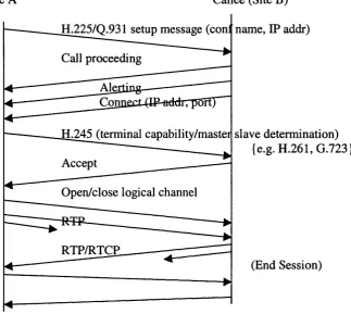
2.1.2.2 Sequence of operations in H.323 based conferencing
When the H.323 based conference runs over UDP it uses RAS (Registration, Admission and status) to setup the call. When the underlying transport protocol is TCP, the call setup messages are sent on the first TCP connection and the caller establishes the callee. Four setup messages: Setup, Alerting, Connect and Release Complete are necessary. Their operations and syntax are defined in detail in the Q.931 and H.225 specifications. The call signalling specified in H.225 follows a set of setup messages through a reliable channel which is based on the Q.931 protocol. H.245 uses the reliable H.225 call signalling channel to perform H.245 control functions, such as master/slave determination and conference control. During the terminal capability exchange procedure, both ends are based on their own terminal capability to set up the mutual acceptable bearer service to the network. Then logical channel (s) are opened to provide the bearers, for example, two channels for video and one for audio. This procedure is very similar to the bearer capability request in the ISDN Q.931 and SS7 ISUP.
Figure 8 shows the sequence of actions for setting up a conference in H.323. The caller sends Setup to initiate the conference immediately after establishing TCP connection.
The Setup message contains the caller’s name and IP address. The callee sends Alerting
Site A
H.225/Q.931 setup message (con; Call proceeding
H.245 (terminal capability/mastei Accept
Open/close logical channel
RTP/RTCP
Callee (Site B) name, IP addr)
slave determination) {e.g. H.261, 0.723}
(End Session)
Figure 8: Message sequence in a H.323 based conferencing
2.1.2.3 Netmeeting - A product based on H.323
perform server transactions such as logging on and off and creating a directory listing of available users.
2.1.3 H.Loosely Based Conferencing
ITU based conferencing does not scale to very large numbers of participants because it uses a centralised architecture relying on a Multipoint Control Unit MCU to distribute media or data to multiple clients. The concept of H.Loosely coupled conferencing has been introduced to address the scalability problem. The main idea is to separate passive “listening” participants from interactive participants.
As shown in Figure 9, there is a panel in this type of conferencing, which consist of active participants who are senders and receivers of data and/or audio. The main principles of tightly coupled conferencing apply to the panel members. This panel consists of a small H.323 conference connected to a large number of RTF receiving terminals via RTP/RTCP. Within the panel, full interaction is allowed. Interaction could be through social- or chair- control.
S m all H .323 P anel T ig h tly -C o u p led C o n feren ce (D ecen tralized m o d el show n) H .323
H .323 H.24
C h air H .323 H .323
R T F R T F R T F R TF R eceiv er R eceiv er R ec eiv er R eceiv er
Large R T F /R T C F -B ased L o o sely -C o u p led C o n feren c e
RTF R eceiv er
R TF R eceiv er
R T F R ec eiv er
R T F R eceiv er
R T F R eceiv er
R T F /R T C F A udio S ession
R T F /I T C F V ideo Session
R T F R T F R T F R T F R T F R T F R eceiv er R eceiv er R ec eiv er R eceiv er R ec eiv er R ec eiv er
Outside the panel, the participants are passive; they are essentially receivers who are not allowed to interact. If they wish to interact, they have to join the panel or get invited by the panel. Inside the panel any H.323 model - centralised, decentralised, or hybrid - can be used. But outside the panel multicast is used in order to provide the scalability required for the H.Loosely coupled conference. This can be achieved by using a Multipoint MP to multicast media streams to the RTP receiving terminals.
• Summary
The infrastructure for ITU standardised conferencing follows a very formal policy where call setup emulates the design used in the POTS networks. The functionality assessed from this type of conferencing can be listed as follows:
• A strict conference control functionality to enforce policies; • Reservation services for conferences and conference resources
• Support of conductorship and (for conducted conferences) of floor control
• Administrative functions for managing applications within the conference including capability negotiation, resource arbitration and address translation (from telephone network to IP netowork)
• Application protocols ( e.g. T.127) for whiteboard, file transfer and remote device control
• A high layer entity (such as MCU) is responsible for organising nodes in a hierarchy based conference
2.2 The IETF architecture for multimedia conferencing
Various working groups have contributed to the development of a teleconferencing architecture in the IETF. These efforts started in the late 1980s with the work on multicasting for the Internet protocol in order to support group communication [Deering91]. Afterwards, improvements to the multicast routing infrastructure - the Multicast Backbone, Mbone (see section 2.3.1) [Mbone] have been achieved and resource reservation mechanisms to achieve a reasonable service quality have been worked out [Zhang93]. The Mbone has been used for a number of applications including multimedia (audio, video and shared workspace) conferencing. These applications involved vat (LBL’s Visual Audio Tool), ivs (INRIA Video Conferencing system), rat (UCL’s Robust Audio Tool), nv (Xerox’s Network Video Tool), wb (LBL’s shared whiteboard), and vie (LBL’s ) among others. The main distinctions between this type of architecture and the ITU’s video conferencing architecture are a) in the IETF based conferencing architecture, all the protocols use a distributed architecture b) these protocols mainly work over IP and the control of conferences is very loosely coupled.
2.2.1 lETF’s basic requirements and design
As mentioned above, the IETF based conferencing architecture consists of several independent protocols which operate in a stand-alone manner. For example, the protocol that is used to advertise a conference is called SAP (Session Announcement Protocol), and RTP (Real-time Transport Protocol) is used to carry audio and video. The design of the lETF’s conferencing system have been made in a modular fashion. In ITU’s architecture, an H.323 conference combines the audio, video, invitation functions (H.225) and conference control (H.245) to provide an integrated solution for a conferencing. In contrast, lETF’s audio tool is separated from the video tool and the protocol for advertising can be separated from the signaling protocol (Session Initiation Protocol).
consistency between all participants, and so they do not attempt to do so [Handley]. The conference control they support usually consists of:
• Periodic (unreliable) multicast reports of receivers
• The ability to locally mute a sender if one does not wish to hear them.
2.3 Different protocols
The following sections describe all the major components and the protocols that contribute towards the IETF based conferencing architecture.
2.3.1 Mbone
The multicast backbone, or Mbone [Mbone], implements IP multicast. During 1991, IP multicast was deployed on the DARTnet testbed network. In spring 1992, the DARTnet's native multicast network was extended to cover a small number of additional sites by tunnelling IP multicast across parts of the Internet without native multicast support. As a temporary measure, the Mbone (Multicast Backbone) was put together to allow reception of live audio from the IETF meeting in San Diego. Forty subnetworks in 4 countries and three continents were able to receive audio and talk back to the meeting. Although the audio quality was poor, the principle had demonstrated, and sufficient interest shown that the Mbone was not taken down again.
2.3.2 Session Directory Protocol (SDP)
A session description expressed in SDP [SDP] is a first generation of conference control for Mbone based conferencing in the manner of a Session Directory - comparable to a TV program listing. SDP is a short structured textual description o f the name and purpose of a conferencing session. SDP lists the media, protocols, codec formats, timing and transport information that are required to decide whether a session is likely to be of interest and to know how to start media tools to participate in the session.
SDP is purely a format for session description - it does not incorporate a transport protocol, and is intended to use different transport protocols as appropriate, including the Session Announcement Protocol (discussed in section 2.3.3), Session Initiation Protocol (section 2.3.4), Real-Time Streaming Protocol, electronic mail using the MIME extensions, and the Hyper-Text Transport Protocol (HTTP).
mjh 2890844526 2890942807 IN IP4 128.16.6.4 Multimedia seminar _________________ x . Seminar on Internet multimedia
IijjIv/ / \\ w v\ , c s .ik‘LK:,i!k
mjh' iM.cclu (markhandley) IN IP4 224.2.17.12/127 t = 873397496 2873404696. Recvonly
Audio 49170 RTP/AVP 0 Application 32416 udp wb Orient:portrait
Video 51372 RTP/AVP 31
\v Originator
\ S e s s i o n ID and version timestamp Originating host
Title
Information about the session URL for more information Email address to contact
Connection information (multicast address & TTL)
Start time (NTP timestamp) Stop time (NTP timestamp)
Attribute indication session is receive only PCM audio using RTP on port 49170 Wb application on port 32416
Wb is in portrait mode
H.261 video using RTP port 51372
In Figure 10 the session entitled “ Multimedia Seminar”, will use audio, video and an application called “ wb”, and that someone called “ Mark Handley” is responsible for the session.
However, this SDP also indicates the precise timing of the session (the “ t=” line gives start and stop times), that the session is multicast to group 224.2.17.12 with a TTL of 127, the audio is 8KHz law carried by RTF to UDP port 49170, the video is H.261 encoded, also over RTP but to port 51372, and the whiteboard program should be started up in portrait mode using port 32416.
Thus SDP includes the session name and a description of its purpose, the times the session is active, the media comprising the session, and information to receive those media (addresses, ports, formats and so on).
As resources necessary to participate in a session may be limited, some additional information may also be desirable, including information about the bandwidth to be used by the conference and contact information for the person responsible for the session.
In general, SDP must convey sufficient information to be able to join a session (with the possible exception of encryption keys) and to announce the resources to be used to non participants that may need to know.
2.3.3 Session Announcement Protocol (SAP)
2.3.4 Session Initiation Protocol (SIP)
The problem of not being able to invite users was solved by the second generation of conference control tools. The required functionality is provided by the Session Initiation Protocol SIP [SIP]. It is a simple, one step conference initiation protocol with basic support for address resolution, call forwarding and redirection. It is currently under development within the IETF MMUSIC (Multiparty Multimedia Session Control) working group. The protocol format is derived from SDP with elements from Hypertext Transfer Protocol (HTTP). SIP is a very lightweight signaling protocol with 6 methods and 20 header fields, mostly self-describing. Also it is meant to scale better (uses DNS) than signalling protocols designed in ITU.
whereis ve?
3
INVITE [email protected]
200 OK
Loniaci! eveiffeasnsreatr
ns.isi.edu
ÊSI
eve is at east
INVITE
east.isi.edu
c
. Contact:
lsi.edu [email protected]
Figure 11 : SIP Request Being Relayed
conferencing. Instead east.isi.edu routes the call to her regular telephone and it acts as a gateway into the department PBX.
The example above uses proxies that relay the SIP call. Relaying is often performed when the gateway or firewall to a site wishes to hide any search that goes on internally from the caller’s machine.
• Summary
The IETF model of conferencing supports large groups of humans and deliver real-time information at a number of levels. The functionality can be summarised as below:
• The Mbone based conferencing are multicast based
• It lacks explicit session membership and explicit conference control mechanisms • These sessions consist of a number of many-to-many media streams supported using
Real time Transport Protocol (RTP) [RTP] and Real time Transport Control Protocol (RTCP) using IP multicast. The only conference control information available during the course of a session is that distributed in the RTCP session information, i.e. an approximate membership list with some attributes per member [RTP].
• In traditional Internet, network resources are not explicitly reserved which may be required for real time delivery of audio and video for the duration of a conference. In IETF new service model and protocols (such as RSVP) to reserve capacity is defined which is more flexible than that available with circuit switching.
• Distributed architecture to advertise sessions (SAP) and invite participants in a conference (SIP) which are “light weight” protocols
![Figure 2 Meeting Types [Source: Schooler [Schooler93]]](https://thumb-us.123doks.com/thumbv2/123dok_us/8611628.1401336/16.595.38.412.207.579/figure-meeting-types-source-schooler-schooler.webp)