University of South Carolina
Scholar Commons
Theses and Dissertations
2018
System Optimization and Material Development
of Solid Oxide Cells for Energy Conversion and
Storage
Libin Lei
University of South Carolina
Follow this and additional works at:https://scholarcommons.sc.edu/etd
Part of theMechanical Engineering Commons
This Open Access Dissertation is brought to you by Scholar Commons. It has been accepted for inclusion in Theses and Dissertations by an authorized administrator of Scholar Commons. For more information, please contactdillarda@mailbox.sc.edu.
Recommended Citation
System Optimization and Material Development of Solid Oxide Cells
for Energy Conversion and Storage
by
Libin Lei
Bachelor of Engineering
Guangdong University of Technology, 2010
Master of Engineering
South China University of Technology, 2013
Submitted in Partial Fulfillment of the Requirements
For the Degree of Doctor of Philosophy in
Mechanical Engineering
College of Engineering and Computing
University of South Carolina
2018
Accepted by:
Fanglin (Frank) Chen, Major Professor
Kevin Huang, Committee Member
Xinyu Huang, Committee Member
John R. Regalbuto, Committee Member
ii
© Copyright by Libin Lei,2018
iii
ACKNOWLEDGEMENTS
First, I would like to express my gratitude to my advisor, who has provided his
knowledge, experience and insightful guidance during my doctoral study. Not only his
encourage but also his critical comments for my study and research are the sources of
energy for my progress. I would also like to thank my thesis committee members, Dr. Kevin
Huang, Dr. John R. Regalbuto and Dr. Xinyu Huang for their invaluable suggestions and
continuous support during my PhD study. Financial supports from the U.S. National
Science Foundation (DMR-1210792), the US Department of Energy SECA Core
Technology Program (under award number DE-FE0031176) are gratefully acknowledged.
Second, I would like to express my appreciation to my colleagues for their assistance
and contributions to my research. It is great to have some encouraging discussions and
cooperation with some of my colleagues, namely Dr. Shumin Fang, Dr. Tong Liu, Dr. Yao
Wang, Dr. Yu Chen, Dr. Cong Ren, Dr. Zetian Tao, Dr. Xiaoming Wang, Dr. Jing Chen
and Mr. Jihao Zhang.
Finally, I am very thankful for my parents, my girlfriend and my family. They support
and encourage me when I am following my dream.
iv
ABSTRACT
Solid oxide cells (SOCs) can convert chemical energy to electricity in the fuel cell
mode and store electricity to chemicals in the electrolysis mode. However, there are still
critical barriers, such as energy efficiency and durability, for the development and
commercialization of SOCs. The objective of this dissertation is to apply system
optimization and materials design to address the critical barriers for solid oxide cells in
energy conversion and energy storage applications. One major focus of the dissertation is
related to improve energy efficiency, enhance the cell performance and achieve
multifunctionality in solid oxide electrolysis cells (SOECs). In addition, development of
robust air electrode and mitigation of Cr poisoning in the air electrode of solid oxide fuel
cells (SOFCs) is also pursued.
Electrolysis of steam or carbon dioxide using SOECs is a promising energy storage
method that can efficiently convert electrical energy into chemicals. In conventional
SOECs, a significant portion of electricity input is consumed to overcome a large oxygen
potential gradient between the electrodes. Therefore, to reduce the electricity consumption
and improve the system efficiency, a novel and efficient syngas generator, integrating
carbon gasification and solid oxide co-electrolysis, is presented and evaluated in the first
part of this dissertation. The feasibility of this new system is demonstrated in
La0.9Sr0.1Ga0.8Mg0.2O3 (LSGM) electrolyte-supported SOECs. Both thermodynamic
v
be reduced by about 1 V and the electricity consumption can be reduced by more than 90%
upon integration SOECs with carbon gasification. On the anode side, “CO shuttle” between
the electrochemical reaction sites and solid carbon is realized through the Boudouard
reaction (C+CO2=2CO). Simultaneous production of CO on the anode side and CO/H2 on
the cathode side generates syngas that can serve as fuel for power generation or feedstock
for chemical plants. The integration of carbon gasification and SOECs provides a potential
pathway for efficient utilization of electricity, coal/biomass, and CO2 to store electrical
energy, produce clean fuel, and achieve a carbon neutral sustainable energy supply.
In the second part of this dissertation, to achieve multifunctionality and regulate
product in SOECs, a novel micro-tubular electrochemical reactor is studied, in which high
temperature co-electrolysis of H2O-CO2 and low temperature methanation processes are
synergistically integrated. The temperature gradient along the micro-tubular reactor
provides favorable conditions for both the electrolysis and methanation reactions.
Moreover, the micro-tubular reactor can provide high volumetric factor for both the
electrolysis and methanation processes. When the cathode of the micro-tubular reactor is
fed with a stream of 10.7% CO2, 69.3% H2 and 20.0% H2O, an electrolysis current of -0.32
A improves CH4 yield from 12.3% to 21.1% and CO2 conversion rate from 64.9% to 87.7%,
compared with the operation at open circuit voltage. Furthermore, the effects of the inlet
gas composition in the cathode on CO2 conversion rate and CH4 yield are systematically
investigated. Higher ratio of H:C in the inlet results in higher CO2 conversion rate. Among
all the cases studied, the highest CH4 yield of 23.1% has been achieved when the inlet gas
in the cathode is consisted of 21.3% CO2, 58.7% H2 and 20.0% H2O with an electrolysis
vi
Furthermore, the state-of-the-art SOECs are based on oxygen-ion conducting
electrolyte (O-SOECs), but SOECs using proton-conducting electrolyte (H-SOECs) offer
the advantages of producing dry and pure hydrogen. However, the development of
H-SOECs falls far behind that of O-H-SOECs, mainly due to technical challenges such as the
stability of the electrolyte and electrode in H2O-containing atmosphere at operating
conditions and the fabrication of thin electrolyte layer. Therefore, in the third part of the
dissertation, BaZr0.8Y0.2O3-δ (BZY) electrolyte and Sr2Fe1.5Mo0.5O6-δ (SFM) air electrode,
both are stable in H2O-containing atmosphere at operating conditions, are evaluated in
H-SOECs. In addition, in order to improve the performance of H-SOECs, thin BZY
electrolyte layer (about 16 μm in thickness) and nano-scaled SFM-BZY air electrode are
fabricated successfully, showing excellent SOEC performance (-0.21 A cm-2 at 600 oC)
and achieving faradaic efficiency of 63.6% at intermediate temperature.
Solid oxide fuel cell (SOFC) is the reverse operation of SOEC and can directly convert
the chemical energy in fuels to electricity with high efficiency and is fuel flexible. The
durability and performance of SOFCs are highly related to the reaction kinetics and
stability of the air electrode. To enhance the reaction kinetics of the air electrode, a novel
hybrid catalyst consisting of PrNi0.5Mn0.5O3 and PrOx is impregnated in the conventional
(La0.60Sr0.40)0.95Co0.20Fe0.80O3-x (LSCF) air electrode of H-SOFCs for the first time. The
effects of this impregnation on the electrochemical performance and durability of
H-SOFCs are investigated in the forth part of the dissertation. Single cells with impregnated
LSCF cathode and BZY electrolyte yield a maximum power density (MPD) of 0.198 W
cm-2 at 873 K, more than doubled than that with blank LSCF cathode (0.083 W cm-2) at
vii
electrochemical impedance spectroscopy (EIS) studies reveal that the hybrid catalyst can
substantially accelerate the oxygen-ion transfer and oxygen dissociation-absorption
processes in the cathode, resulting in significantly lower polarization resistance and higher
MPD. In addition, the hybrid catalyst possesses good chemical and microstructural stability
at 600 oC. Consequently, the single cells with impregnated LSCF cathode show excellent
durability. This study shows that the impregnation of this novel hybrid catalyst in the
cathode could be a promising approach to improve the performence and stability of
H-SOFCs.
Moreover, the state-of-the-art SOFC air electrode is suffering from
chromium-poisoning, leading to high SOFC cell performance degradation. To mitigate the effect of
Cr poisoning, placing Cr getter between the air electrode and the Cr sources is an efficient
approach. However, the stability of the state-of-the-art Cr getter materials in the SOFC
cathodic operation conditions remains challenging. For the first time, SFM is investigated
as Cr getter material in the fifth part of the dissertation. The reactivity of SFM, which is
stable in an atmosphere containing H2O and CO2, with Cr species (Cr2O3) is evaluated.
Subsequently, the feasibility of SFM as Cr getter material is investigated. The experiment
results show that SFM, which is stable in an atmosphere containing H2O and CO2,
possesses high reactivity and selectivity with Cr species (Cr2O3). Consequently, the
application of SFM layer can efficiently capture the gaseous Cr species, resulting in
viii
TABLE OF CONTENTS
ACKNOWLEDGEMENTS ... iii
ABSTRACT ... iv
LIST OF TABLES ...x
LIST OF FIGURES ... xi
CHAPTER 1 INTRODUCTION ...1
1.1 BACKGROUND ABOUT SOLID OXIDE ELECTROLYSIS CELLS ... 1
1.2 THERMODYNAMICS OF ELECTROLYSIS ... 3
1.3 MATERIALS OF SOCs ... 6
1.4 CHROMIUM POISONING IN AIR ELECTRODE ... 11
1.5 OBJECTIVE AND STRUCTURE OF THIS DISSERTATION ... 14
CHAPTER 2 EFFICIENT SYNGAS GENERATION FOR ELECTRICITY STORAGE THROUGH CARBON GASIFICATION ASSISTED SOLID OXIDE CO-ELECTROLYSIS ...17
2.1 BACKGROUND ... 17
2.2 EXPERIMENTAL ... 19
2.3 RESULTS AND DISCUSSION ... 21
2.4 CONCLUSIONS... 33
CHAPTER 3 THE CO-ELECTROLYSIS OF CO2-H2O TO METHANE VIA A NOVEL MICRO-TUBULAR ELECTROCHEMICAL REACTOR ...34
3.1 BACKGROUND ... 34
ix
3.3 RESULT AND DISCUSSIONS ... 37
3.4 CONCLUSIONS... 49
CHAPTER 4 INTERMEDIATE-TEMPERATURE SOLID OXIDE ELECTROLYSIS CELLS WITH THIN PROTON-CONDUCTING ELECTROLYTE AND ROBUST AIR ELECTRODE ...51
4.1 BACKGROUND ... 51
4. 2 EXPERIMENTAL ... 54
4.3 RESULT AND DISCUSSIONS ... 57
4.4 CONCLUSIONS... 68
CHAPTER 5 A HIGHLY ACTIVE HYBRID CATALYST MODIFIED LSCF CATHODE FOR PROTON CONDUCTING SOLID OXIDE FUEL CELLS ...70
5.1 BACKGROUND ... 70
5. 2 EXPERIMENTAL ... 72
5.3 RESULT AND DISCUSSIONS ... 75
5.4 CONCLUSIONS... 84
CHAPTER 6 AN EFFICIENT AND HIGH-SELECTIVITY CHROMIUM GETTER FOR SOLID OXIDE FUEL CELLS ...85
6.1 BACKGROUND ... 85
6. 2 EXPERIMENTAL ... 87
6.3 RESULT AND DISCUSSIONS ... 89
6.4 CONCLUSIONS... 98
FUTURE WORK ...99
x
LIST OF TABLES
Table 2.01 Comparison of electricity consumption for 1 mole ... 32
syngas production in the CG assisted and conventional mode. ... 32
Table 3.01 Gibbs free energy (kJ/mol) of methanation reactions. ... 38
Table 3.02 Direct synthesis of methane in solid oxide electrolysis cells... 46
Table 3.03 CO2 conversion ratio, CH4 yield ratio and CH4 yield rate ... 46
Table 4.01 Comparison of the performance of typical H-SOFCs with BZY as the electrolyte ... 63
Table 4.02 Comparison of the performance of H-SOECs at 1.3 V ... 67
xi
LIST OF FIGURES
Figure 1.01 Schematic of O-SOEC and H-SOEC. ... 2
Figure 1.02 Thermodynamics of H2O and CO2 electrolysis[9]. ... 3
Figure 1.03 Schematic of chemical and morphological changes at air electrode-electrolyte interface during electrolysis[22]. ... 9
Figure 1.04 Partial pressure of CrO2(OH)2 in wet air (3%H2O) and CrO3 in dry air over
Cr2O3 scale at different temperature[39]. ... 12
Figure 2.01 Schematic illustration of carbon gasification assisted solid oxide co-electrolysis. ... 21
Figure 2.02 Thermodynamic calculation as function of temperature for co-electrolysis process (a) conventional mode and (b) CG assisted mode. ... 22
Figure 2.03 Calculated Ere and Etn as a function of temperature for co-electrolysis process
in the (a) conventional mode, and (b) CG assisted mode. ... 24
Figure 2.04 The microstructure of single cell (a) SFM-SDC/LSGM/SFM-SDC triple layers ; (b) interface of SFM-SDC and LSGM. ... 26
Figure 2.05 (a) I-V curves for the electrolysis cells operated in conventional mode and CG assisted mode at 1123K; (b) impedance spectra for electrolysis cells operated in four different conditions. ... 26
Figure 2.06 (a) Thermodynamic equilibrium calculation results for the reaction of 2 mol O2 with 98 mol carbon at different temperatures; (b) TG and DTG of carbon source in air
and CO2 condition; (c) the exhaust gas composition in the air electrode side. ... 30
Figure 2.07 I-total energy efficiency curves for the electrolysis cell operated in conventional mode and CG assisted mode at 1123K. ... 32
Figure 3.01 Schematic of micro-tubular reactor. ... 37
xii
Figure 3.03 Electrochemical test of the electrolysis region in fuel cell mode with H2 as fuel
at 1023 K, (a) I-V curve; (b) Electrochemical impedance spectrum under OCV. ... 40
Figure 3.04 Electrochemical test of the electrolysis region in the electrolysis mode at 1023 K, (a) I-V curves; (b) impendence spectra under 1.3V. The inlet steam carrier is 15 sccm CO2-H2 with 20 vol% humidity. ... 42
Figure 3.05 Gas composition in the exhaust (a) with the inlet gas composition: 10.7%CO2
-69.3%H2-20%H2O; (b) with the inlet gas composition: 21.3%CO2-58.7% H2-20.0% H2O;
and (c) with inlet gas composition: 32.0%CO2-48.0%H2-20.0%H2O. ... 43
Figure 3.06 Short term stability of the micro-tubular reactor (a) stability of the electrolysis region and (b) the gas composition in the exhaust. ... 48
Figure 3.07 SEM images of the Ni-YSZ substrate (a) before the stability test; (b) after the stability test in the methanation region and (c) after the stability test in the electrolysis region. ... 49
Figure 4.01 Schematic of proton conducting solid oxide electrolysis cell with SFM as the air electrode. ... 54
Figure 4.02 XRD patterns showing (a) chemical compatibility between SFM and BZY (b) the stability of SFM in 20%H2O-air at 873 K... 58
Figure 4.03 The stability of LSCF in 20%H2O-Air at 873 K. ... 58
Figure 4.04 Electrochemical characterization of symmetrical cell (a) Impedance spectra in wet air (3% H2O) at 873 K and its equilibrium circuit; (b) Arrhenius plot of polarization
resistances. ... 59
Figure 4.05 SEM image (a) the cross section of single cell; (b) the surface of the BZY electrolyte; (c) the microstructure of SFM-BZY electrode at low magnification; (d) the microstructure of SFM-BZY electrode at high magnification. ... 60
Figure 4.06 Electrochemical performance of single cells in the fuel cell mode (a) I-V curves at different temperatures; (b) Impedance spectrum under OCV at 873 K. ... 62
Figure 4.07 I-V curves of single cell in electrolysis mode (3%H2O-air in air electrode,
90%N2-10%H2 in air electrode). ... 63
Figure 4.08 Short term stability in electrolysis mode (a) Current vs time; (b) SEM image of SFM-BZY air electrode after the stability test; (c) Hydrogen evolution rate and faradaic efficiency... 64
Figure 5.01 Schematic illustrations of blank LSCF electrode and PNM-PrOx impregnated
xiii
Figure 5.02 XRD patterns (a) chemical compatibility between PrNi0.5Mn0.5O3, PrOX, and
BZY; (b) Stability of PrNi0.5Mn0.5O3 and PrOX. ... 75
Figure 5.03 FESEM images of the single cells. (a) The surface of the BZY electrolyte; (b) The cross-section view of NiO-BZY anode and BZY electrolyte. ... 76
Figure 5.04 FESEM image of cathode (a) Microstructure of bare LSCF electrode; (b) Microstructure of LSCF electrode with PrNi0.5Mn0.5O3 and PrOX; (c) High magnification of image of LSCF electrode with PrNi0.5Mn0.5O3 and PrOX. ... 77
Figure 5.05 Electrochemical performance of single cells (a) I-V curves; (b) Maximum powder densities of single cells at various temperature. ... 77
Figure 5.06 (a) Impedance spectra Impedance spectra of single cells at 650 oC; (b) Polarization resistance of single cells at various temperatures; (c) Polarization resistance RH at various temperatures; (d) Polarization resistance RL at various temperatures. ... 78
Figure 5.07 (a) Electrical conductivity relaxation as a function of time at 973 K; (b) Plots of the surface exchange coefficients (Keff) as function of temperatures. ... 80
Figure 5.08 (a) Stability of single cells at 873 K (a) Operation of single cells at 0.6 V; (b) The microstructure of electrode after 100 h test. ... 81
Figure 6.01 The schematic of test setup... 89
Figure 6.02 The XRD patterns of SFM, Cr2O3 and mixture (1:1) before treatment... 90
Figure 6.03 The XRD patterns of SFM after CO2 and H2O treatment. ... 90
Figure 6.04 The XRD patterns of SFM-Cr2O3 mixture (1:1) after treatment (a) at 1223 K and 1123 K; (b) at 1023 K and 923 K. ... 91
Figure 6.05 The XRD patterns of SFM-Cr2O3 mixture (10:1) after treatment at 973 K and 1073K. ... 92
Figure 6.06 Impedance spectra of LSCF at 1073 K (a) Blank; (b) with Cr2O3; (c) with Cr2O3 and SFM getter. ... 93
Figure 6.07 Equilibrium circuit and fitting results of impedance spectra in Fig. 6.06(b). 95 Figure 6.08 Microstructure characterization of LSCF (a) blank before test; (b) blank after test; (c) with Cr source; (d) with Cr sourceand SFM getter. ... 95
1
CHAPTER 1 INTRODUCTION
1.1 BACKGROUND ABOUT SOLID OXIDE ELECTROLYSIS CELLS
Fossil fuels, such as coal, oil and natural gas, are non-renewable energy resources and
their ever-increasing consumption has led to excessive emission of greenhouse gases such
as CO2. Therefore, carbon emission reduction needs to be implemented and renewable
energy sources have actively been developed globally in the past decades. Renewable
energy sources such as wind and solar are now increasingly harvested to generate
electricity, but the intermittent nature of these energy sources requires the capacity for
large-scale electrical energy storage. Therefore, it’s essential to develop efficient electricity
storage technologies.
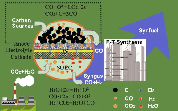
Electrolysis of steam/carbon dioxide by solid oxide electrolysis cells (SOECs) is a
promising energy storage method that can efficiently transform electrical energy into
non-fossil syngas (a mixture of H2 and CO) which can be converted to electricity when
required[1-3]. Meanwhile, it is an excellent alternative for CO2 utilization due to its high
conversion rate and flexibility[4, 5]. The produced syngas can also be subsequently used
as feedstock through the well-established Fischer-Tropsch (F-T) process to produce liquid
synthetic fuel that can be easily stored and transported using the existing infrastructure
compared with the alternative hydrogen[6]. Compared with low-temperature proton
exchange membrane (PEM) electrolyzers and alkaline electrolyzers, high temperature
SOECs offer significant advantages. For example, besides hydrogen, syngas can be
2
achieved for its high operation temperature[7]. In the past decade, there have been
increasing research interests in SOECs[8].
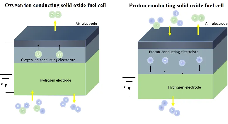
Figure 1.01 Schematic of O-SOEC and H-SOEC.
According to the types of the electrolyte, SOECs can be classified into two kinds,
namely oxygen-ion conducting SOECs (O-SOECs) and proton conducting SOECs
(H-SOECs), as shown in Fig. 1.01. In O-SOECs, the electrolyte is oxygen ion conductor.
Steam is fed to the porous hydrogen electrode side. When the required electrical potential
is supplied to the SOECs, water molecules diffuse to the reaction sites and are dissociated
to form hydrogen gas and oxygen ions at the triple phase boundaries of the hydrogen
electrode. The produced hydrogen gas diffuses to the hydrogen electrode surface and is
collected. The oxygen ions are transported through the electrolyte layer to the air electrode.
On the air electrode side, the oxygen ions are oxidized to oxygen gas. The reactions in each
3
Hydrogen electrode: H2O+2e-=H2+O2- (1.01)
Air electrode: O2-=0.5O2+2e- (1.02)
Overall reaction: H2O=H2+ 0.5O2 (1.03)
By contrast, the electrolyte is proton conductor in H-SOECs. Steam is fed to the air
electrode side. When the required electrical potential is applied to the H-SOECs, water
molecules diffuse to the reaction sites and are dissociated to form protons, oxygen gas and
electrons at the triple phase boundaries of the air electrode. The protons are transported
through the electrolyte layer to the hydrogen electrode side and then accept electrons to
produce hydrogen gas. The reactions in each electrode as well as the overall reaction can
be written as:
Hydrogen electrode: 2H++2e-=H2 (1.04)
Air electrode: H2O=2H++2e-+0.5O2 (1.05)
Overall reaction: H2O=H2+ 0.5O2 (1.06)
1.2 THERMODYNAMICS OF ELECTROLYSIS
Figure 1.02 Thermodynamics of H2O and CO2 electrolysis[9].
Fig. 1.02 shows the thermodynamics of H2O and CO2 electrolysis. The total energy
4
and CO2 electrolysis. The heat demand (T△Sf) increases with increasing temperature, while
the electrical energy demand (△Gf) shows the opposite trend. In other words, at elevated
temperature, a significant part of the total energy demand can be provided as heat instead
of electricity. In addition, this provides an opportunity to utilize the heat that is inevitably
produced when electrical current is passed through the electrolysis cell. Consquently, the
overall consumption of electrical energy is reduced and the efficiency for production of H2
and/or CO can be increased, when the operation temperature of electrolysis is increased.
This nature of electrolysis provides advantages to SOECs operated at high temperature,
compared with low temperature electrolysis cells.
During the operation of electrolysis, a voltage (E), which is higher than open circuit
voltage (reversible voltage Ere), is required to be applied to the electrolysis cells. Reversible
voltage Ere is defined as the minimum voltage required for splitting of either H2O or CO2.
The thermodynamic definition of Ere is as equation (1.07):
nF G Ere
(1.07)
where △G is Gibbs free energy of reaction, n is the number of electrons involved in the
reaction and F is the Faraday constant.
In addition, thermoneutral voltage Etn is another important parameter in SOECs. It is
defined as the voltage at which the generated heat in the electrolysis cell and the heat
consumption are equal. The thermodynamic definition of Etn is as equation (1.08)[9]:
nF H
Etn (1.08)
where △H is the molar enthalpy change of reaction.Theoretically speaking, there are three
5
status (Qre<Qir) and thermoneutral status (Qre=Qir). Where Qre and Qir are the reversible
heat and irreversible heat respectively. When the operating voltage (Vop) of electrolysis is
between Ere and Etn (Ere < Vop <Etn), extra heat input is needed to balance the enthalpy
change (endothermic status). In exothermic mode, the operating voltage is higher than the
thermoneutral voltage (Vop >Etn), extra heat, produced from resistance of the electrolysis
cell, has to be removed from the system. When operating the electrolysis cell under
thermoneutral condition (Vop =Etn), no extra heating and cooling is needed. Because
compared with heat, electricity is a more valuable form of energy, electricity is not desired
to transform into heat redundantly. Therefore, the SOECs is preferred to be operated in
endothermic status and especially in thermoneutral status.
In practice, the partial pressure of reactants or products is usually not 1. Especially in
SOECs, the inlet gas is always a gas mixture. Consequently, equation (1.07) is not enough
to predict the OCV of SOECs in practical use. In O-SOECs, equation (1.09), as shown
below, is developed for calculation of OCVs:
ectrode hydrogenel O de airelectro O OCV
p
p
F
RT
E
, , 2 2ln
4
(1.09)Where F is the Faraday constant, T the temperature (K), R the gas constant, and,
de airelectro O
p ,
2 and pO2,hydrogenelectrode are the oxygen partial pressure.
In term of H-SOECs, because not only proton but also oxygen ion and electron can
transport through the electrolyte, the calculation of OCVs is more complicated, compared
with that in O-SOECs. Considering the transport number of different carriers, the OCVs of
6
𝐸𝑂𝐶𝑉 = 𝑡𝑜𝐸𝑂+ 𝑡𝐻𝐸𝐻= 𝑡𝑂𝑅𝑇 4𝐹ln (
𝑃𝑂2,𝑎𝑖𝑟 𝑒𝑙𝑒𝑐𝑡𝑟𝑜𝑑𝑒
𝑃𝑂2,ℎ𝑦𝑑𝑟𝑜𝑔𝑒𝑛 𝑒𝑙𝑒𝑐𝑡𝑟𝑜𝑑𝑒) + 𝑡𝐻
𝑅𝑇 2𝐹ln (
𝑃𝐻2,ℎ𝑦𝑑𝑟𝑜𝑔𝑒𝑛 𝑒𝑙𝑒𝑐𝑡𝑟𝑜𝑑𝑒
𝑃𝐻2,𝑎𝑖𝑟 𝑒𝑙𝑒𝑐𝑡𝑟𝑜𝑑𝑒 )
(1.10)
where to and tH are the actual transport numbers of oxygen ions and protons respectively,
EO and EH are the thermodynamic OCV values of oxygen and hydrogen cells. Equation
(1.10) can be presented in another form:
𝐸𝑂𝐶𝑉 = 𝑡𝑖𝐸𝑂+ 𝑡𝐻𝐸𝐻2𝑂 = 𝑡𝑖 𝑅𝑇 4𝐹ln (
𝑃𝑂2,𝑎𝑖𝑟 𝑒𝑙𝑒𝑐𝑡𝑟𝑜𝑑𝑒
𝑃𝑂2,ℎ𝑦𝑑𝑟𝑜𝑔𝑒𝑛 𝑒𝑙𝑒𝑐𝑡𝑟𝑜𝑑𝑒) + 𝑡𝐻
𝑅𝑇 2𝐹ln (
𝑃𝐻2𝑂,ℎ𝑦𝑑𝑟𝑜𝑔𝑒𝑛 𝑒𝑙𝑒𝑐𝑡𝑟𝑜𝑑𝑒
𝑃𝐻2𝑂,𝑎𝑖𝑟 𝑒𝑙𝑒𝑐𝑡𝑟𝑜𝑑𝑒 )
(1.11)
where ti = to + tH is the actual transport numbers of ions, EO and EH are the thermodynamic
OCV values of oxygen and hydrogen cells, pH2O,airelectrode and pH2O,hydrogenelectrode are the
steam partial pressure. If the steam partial pressures are the same in both electrode, equation
(1.11) can be greatly simplified.
1.3 MATERIALS OF SOECs
1.3.1 ELECTROLYTE
According to the classification of SOECs, there are two kinds of electrolyte, namely
oxygen ion conductor and proton conductor. The most widely used oxygen ion conducting
electrolyte is yttria-stabilized zirconia (YSZ), which exhibits high oxygen ion conductivity
at high temperature (above 1073 K) and good mechanical strength. However, the typical
high operating temperature (above 1073 K) results in high performance degradation rate in
the range of 1-4%/1000h and high material cost. Therefore, lowering the operation
temperature of SOECs can potentially improve durability, reduce materials issues, increase
7
efficiency. But relatively low oxygen ion conductivity of YSZ at intermediate temperature
(below 973 K) limits its application.
For the application at intermediate temperature (below 837K to 973 K), doped
lanthanum gallate is alternative electrolyte material for O-SOECs. The doped LaGaO3
material has been found to have good ionic conductivity. The conductivity of
La0.9Sr0.1Ga0.8Mg0.2O3 (LSGM) has been reported to be 0.17 S/cm at 1073 K, which is
much higher than YSZ (0.026S/cm at 1073 K)[7]. However, LSGM is suffering serious
reactions with Ni on the hydrogen electrode [7]. This will require modification of the
conventional nickel based fuel electrode to avoid the formation of LaNiO3 and facture due
to thermal expansion coefficient (TEC) mismatch between electrolyte and electrodes.
Similar to LSGM, the doped ceria is considered as a potential
intermediate-temperature electrolyte for SOFC because of its high oxygen ions conductivity at a
temperature between 773 and 973 K [11]. However, partial reduction of Ce4+ to Ce3+ in
reducing environment leads to significant electronic conduction. As a result, a partial
internal electronic short-circuit happens in the electrolyte, leading to decrease of the current
efficiency and lattice expansion which may lead to mechanical failure[12].
For proton conducting electrolyte, there are mainly two groups, namely proton
conducting cerate and zirconate oxides. The electrolyte material is required to be stable in
H2O-containing atmosphere in the operating conditions. However, proton-conducting
cerate oxides, which are the most-widely investigated material for proton-conducting solid
oxide fuel cells (H-SOFCs), have been shown to be chemically unstable in H2O-containing
atmosphere both thermodynamically[13] and experimentally[14] at typical cell operating
8
conducting cerate oxide in H2O-containing atmosphere[15, 16]. On the contrary,
proton-conducting zirconate oxides have been proven to be chemically stable in H2O-containing
atmosphere[17, 18], making them the choice electrolyte for H-SOECs.
1.3.2 AIR ELECTRODE MATERIAL
In O-SOECs, the steam is fed to the hydrogen electrode and the air electrode is still
exposed to dry air atmosphere, which is the same of O-SOFCs. Therefore, conventional air
electrode materials of O-SOFCs can be applied to O-SOECs directly. So far, lanthanum
strontium manganate (LSM) is the most widely used air electrode material for O-SOECs
[19, 20]. However, it has been reported that LSM air electrode delaminates from YSZ
electrolyte during electrolysis due to high internal oxygen pressure near the air
electrode-electrolyte interface and the formation of lanthanum zirconate, as shown in Fig. 1.03 [21].
Grave et al. have reported that this electrolysis induced degradation can be completely
eliminated by reversibly cycling between electrolysis and fuel cell mode [22].
The high internal oxygen pressure near the air electrode-electrolyte interface is due to
the low ionic conductivity of LSM (5.93×10⁻⁷ S cm-1 at 1073 K). Mixed ionic electronic
conducting (MIEC) oxides, such as lanthanum strontium cobalt ferrite (LSCF), have been
applied to O-SOECs as air electrode material [23, 24]. In addition, redox stable perovskite
materials, such as Sr2Fe1.5Mo0.5O6-δ (SFM), have also been studied as air electrode material
of O-SOEC. SFM processes high oxygen ionic conductivity (0.13 S cm-1 at 1073 K in air),
reasonable electrical conductivity (14.93 S cm-1 at 1023 K in air) and shows excellent
9
Figure 1.03 Schematic of chemical and morphological changes at air electrode-electrolyte interface during electrolysis[22].
Unlike in O-SOEC, the steam is fed to the air electrode side in H-SOEC, as shown in
Fig. 1.01. Therefore, the air electrode material is required to be chemically stable in
atmosphere with high humidity. Up to now, most of the air electrode materials in H-SOEC
reported are only derived from proton conducting solid oxide fuel cells (H-SOFCs), but the
performance of these conventional H-SOFC air electrode materials doesn’t meet the
requirements of H-SOECs. As an example, LSCF (La0.6Sr0.4Co0.2Fe0.8O3-δ), a conventional
10
its stability in H2O-containing atmosphere is a serious concern, especially at intermediate
temperature range of 873-973 K [26, 27]. Therefore, it is essential to develop new material
for the air electrode of H-SOEC.
1.3.3 HYDROGEN ELECTRODE MATERIALS
The potential hydrogen electrode material has to meet the following requirements
including (1) good catalytic activity, (2) sufficient electronic conductivity, (3) proper
thermal compatibility and (4) good chemical stability.The Ni-based electrode is the most
common hydrogen electrode material for SOECs because of its high electrical conductivity,
excellent catalytic activity for high temperature steam/CO2 splitting reaction and low
cost[28]. The ionic conductor electrolyte phase such as YSZ or GDC is incorporated in
hydrogen electrode to increase the ionic conductivity, match the thermal expansion
coefficient (TEC) with the electrolyte and extend the triple phase boundaries (TPBs).
SOECs with the Ni-based hydrogen electrode have displayed good electrochemical
performance with low polarization resistance and high electrolysis current density [29, 30].
Although the nickel-based cermets are the most common hydrogen electrode material
for SOECs, Ni has poor tolerance to impurity poisoning and is susceptible to microstructure
changes from thermal or redox cycling, resulting in loss of TPBs and cell performance
degradation in long-term operations [25, 31]. Consequently, new ceramic materials such
as LaCrO3, SrTiO3, SFM, and LaVO3-based materials have been investigated as alternative
and more stable hydrogen electrode materials for SOECs.
Pervoskite LaCrO3-based materials are stable and conductive in both reducing and
oxidizing atmospheres. They are widely used as interconnect material and have been
11
electronic and ionic conductivity is tunable by adjusting the co-doping of divalent ions
such as Sr2+, Ca2+ and Mg2+ to the A-sites and transition metal ions such as Mn2+, Fe2+ and Co2+ to the B-sites [32-34].
Perovskite oxide LaxSr1-xTiO3+δ (LST) is another alternative ceramic hydrogen
electrode material for SOECs. It is a typical n-type semiconductor and can achieve an
electrical conductivity as high as 30 S cm-1 at intermediate temperature upon reduction in
reducing atmosphere. Furthermore, LST is stable in pure H2 up to 1673 K. Therefore, LST
has attracted much attention to be used as hydrogen electrode materials in the SOC [35].
Xie et al. have utilized the electronic conductor (LST) and oxygen-ion conductor (GDC)
to form LST-GDC composite hydrogen electrode for co-electrolysis application. The
electrolyte-supported SOECs with the cell configuration of LST-CGO/YSZ/LSM-GDC
functioned well in the electrolysis conditions even without using hydrogen as the reducing
gas as typically required in the electrolysis cells using nickel-based hydrogen electrode[36].
Perovskite Sr-doped LaVO3 (LSV) exhibits high electronic conductivity about 120 S
cm-1 at 1073 K, and it is also very stable over a wide range of oxygen partial pressure from 10-4 to 10-22 atm with considerable sulfur tolerance and coking resistance at elevated temperature. Yoon et al. [37] have reported the co-electrolysis performance of LSV-YSZ
composite materials as hydrogen electrode for electrolyte-supported cells with the
configuration of LSV-YSZ/YSZ/LSF-YSZ, which exhibited the cell polarization
resistance of 0.89 Ω cm2 at 1073 K in the 70% (20% CO-80% CO
2)–30% H2O atmosphere. 1.4 CHROMIUM POISONING IN AIR ELECTRODE
The reducing operation temperature of SOCs greatly increases the feasibility of using
12
such as Sr-doped lanthanum chromite, metallic materials have high electronic and thermal
conductivity, negligible ionic conductivity, good machinability and low cost. However, the
oxidation and corrosion on metal surface becomes problematic at elevated SOCs operating
temperatures, which may lead to substantial increase in the ohmic resistance of SOC stack.
High Cr content alloys draw significant attention because of their anti-oxidation property
at high temperatures. However, the volatilization of gaseous Cr-species from the alloy
surface leads to drastically degradation of air electrode performance which becomes a
serious issue in SOC development and commercialization [38]. Cr vaporization is affected
by serval factors such as the flow rate, flow regime, temperature and humidity. The
representative vapor species of Cr are CrO3 in dry air and CrO2(OH)2 in wet air. Fig. 1.04
shows the temperature dependence of the partial pressure of these two main Cr species over
Cr2O3 scale in wet and dry air, respectively [39]. From Fig. 1.04, it can be seen that the
partial pressure of CrO2(OH)2 is larger than that of CrO3, suggesting that Cr vaporization
is more serious in wet air than in dry air. In addition, the partial pressures of CrO2(OH)2
and CrO3 increase with increasing temperature.
Figure 1.04 Partial pressure of CrO2(OH)2 in wet air (3%H2O) and CrO3 in dry air over
13
Two general pathways have been reported for Cr-poisoning, one is the chemical
reaction and the other is the electrochemical reaction. The representative chemical reaction
pathway has been demonstrated by Jiang et al. [38] who have systematically studied the
Cr deposition mechanism in LSM and LSCF air electrode. In LSM, Mn2+ was generated
during air electrode polarization at high temperature, which served as the nucleation agent
for the formation of Cr2O3 from Cr-Mn-O nucleus for LSM, as shown in reactions
(1.12-1.15):
Cr2O3 +3/2O2=2CrO3(g) (1.12)
Mn2++CrO3=Cr-Mn-Ox(nuclei) (1.13)
Cr-Mn-Ox+ CrO3= Cr2O3 (1.14)
Mn2++Cr-Mn-Ox+ CrO3= (Cr,Mn)3O4 (1.15)
In LSCF, SrO served as the nucleation agent for LSCF air electrode, as shown
in reactions (1.16-1.18):
SrO+CrO3=Cr-Sr-Ox(nuclei) (1.16)
Cr-Sr-Ox+ CrO3= Cr2O3 (1.17)
SrO+Cr-Mn-Ox+ CrO3= SrCrO4 (1.18)
In the electrochemical reaction pathway, it has been suggested that volatile
CrO2(OH)2 is formed under typical SOFC operating conditions. These gas phase chromium
species can deposit on the air electrode forming Cr2O3, while the oxide anions diffuse
through the electrolyte, as shown in reaction (1.19):
CrO2(OH)2(g)+6e-= Cr2O3(s)+2H2O+3O2- (1.19)
Whether through chemical or electrochemical pathways, deposition of Cr-containing
14
limits oxygen exchange with the bulk electrolyte, degrading overall fuel cell performance.
Considering the electrochemical pathways, a mixed ionic and electronic conducting air
electrode is more tolerant to Cr-poisoning due to the expansion of the area available for
electrochemical deposition of chromia and the promotion of chromia deposition in less
critical areas instead of only to the air electrode/electrolyte interface for a predominantly
electronic conducting air electrode. In addition, to reduce the concentration of the volatile
chromia species, metallic interconnect surfaces have been subjected to various coatings.
The function of the coating is to form a ceramic phase that is electrically conducting but
has lower chromia evaporation rates. However, coatings also increase the cost for the
metallic interconnects. Complete coverage of the entire metallic surfaces is often difficult
due to the complex geometry for most of the metallic interconnect designs. The long-term
reliability of the coating is also a concern. Consequently, Cr getter materials have been
developed to mitigate the air electrode Cr-poisoning by capturing the volatile Cr-species
before they reach the electrochemically active air electrodes[40, 41]. Uddin et al. [41] have
reported that the application of a Cr getter layer can efficiently prevent Cr poisoning in the
bulk air electrode and air electrode-electrolyte interface. However, the stability of Cr getter
material in operation condition and the replacement of Cr getter layer in SOC stacks are
still problems.
1.5 OBJECTIVE AND STRUCTURE OF THIS DISSERTATION
According to the discussions above, one objective of this proposal is to optimize the
system of SOEC to increase energy efficiency. In conventional SOECs, a significant
portion of electricity input is consumed to overcome a large oxygen potential gradient
15
system efficiency, a novel and efficient syngas generator, integrating carbon gasification
and solid oxide co-electrolysis, is presented. The electrochemical performance and energy
efficiency of this novel system have been investigated and compared with those of
conventional O-SOECs. Furthermore, in the Chapter 3 of this dissertation, for direct
synthesis of methane in co-electrolysis, a novel micro-tubular electrochemical reactor is
presented. High temperature co-electrolysis of H2O-CO2 and low temperature
methanantion processes are synergistically integrated in this reactor. The performance and
stability of this reactor have been studied. The effect of inlet gas composition on the
conversion percentage of CO2 and the yield of CH4 have also been investigated.
Moreover, another objective of this dissertation is focused on developing robust and
high performance air electrode material for proton conducting solid oxide reversible cells
(H-SORC). The development of H-SOCs is far behind that of O-SOCs, mainly due to
technical challenges such as the stability of the electrolyte and electrode in H2O-containing
atmosphere at operating conditions and the sluggish reaction kinetics in the air electrode.
Therefore, in the Chapter 4 of this dissertation, to solve the stability problem,
BaZr0.8Y0.2O3-δ (BZY) electrolyte and Sr2Fe1.5Mo0.5O6-δ (SFM) air electrode, both are
stable in H2O-containing atmosphere at operating conditions, are applied and evaluated
H-SOECs. In the Chapter 5 of this dissertation, to enhance the reaction kinetics in the air
electrode, a novel hybrid catalyst consisting of PrNi0.5Mn0.5O3 and PrOx is impregnated in
the conventional LSCF air electrode of H-SOFCs for the first time. The effects of this
impregnation on the electrochemical performance and durability of H-SOFCs are
16
The volatilization of gaseous Cr-species from Cr containing interconnect materials
leads to drastically degradation of air electrode performance which becomes a serious issue
in SOC development. To mitigate the effect of Cr poisoning, introducing Cr getter between
the air electrode and the Cr sources is an efficient approach. However, the stability of the
state-of-the-art Cr getter materials in the SOFC cathodic operation conditions remains
challenging. For the first time, Sr2Fe1.5Mo0.5O6-δ (SFM) is investigated as Cr getter material
in the Chapter 6 of this dissertation. The reactivity of SFM, which is stable in an atmosphere
containing H2O and CO2, with Cr species (Cr2O3) is evaluated. Subsequently, the feasibility
17
CHAPTER 2 EFFICIENT SYNGAS GENERATION FOR ELECTRICITY
STORAGE THROUGH CARBON GASIFICATION ASSISTED SOLID
OXIDE CO-ELECTROLYSIS
2.1 BACKGROUND
There are some paramount challenges for the large scale deployment of SOECs[8,
30, 42, 43]. One major challenge is that a significant portion of electricity input is
consumed to overcome a large oxygen potential gradient (open circuit voltage up to 1 V)
in the co-electrolysis process, because the air electrode is often exposed to air with a high
oxygen partial pressure[44]. Considering that the electrical consumption is crucial for its
commercial competitiveness, it is very desirable to reduce the oxygen partial pressure of
the air electrode in order to lower the open circuit voltage (OCV). Furthermore, utilization
of oxygen produced in the air electrode is also vital for improving the overall system
efficiency. However, there are only very limited reports concerning the reduction of
oxygen potential gradient in SOECs. Martinez-Frias et al. reported that natural gas
assistance can reduce the OCV of electrolysis and improve the efficiency with heat
recovery system[44]. Wang et al. reported that introduction of reducing gases (CH4 or CO)
in the air electrode can decrease the electrochemical potential required for electrolysis [45,
46]. However, in these studies, the utilization of oxygen produced in the air electrode is
18
oxidation of methane and co-electrolysis, in which the potential barrier is reduced and
oxygen (produced in the air electrode) is utilized to partially oxidize methane to produce
syngas[47].
Carbon gasification (CG) is a process to transform carbon-containing solids (such as
coal and biomass) into gaseous fuels such as CO, H2, and CH4. It has emerged as a clean
and effective way for the production of gaseous fuels that can be used for power generation
or synthesis of chemicals [48, 49]. CG is already a well-developed technology and has been
widely applied in Integrated Gasification Combined Cycle (IGCC), production of syngas,
and solid oxide fuel cells (SOFCs) [50-62]. Similarly, solid oxide co-electrolysis and CG
process can be synergistically combined and an integrated paradigm can be achieved. The
production of CO by carbon gasification in the air electrode side can eliminate the uphill
potential barrier in SOECs. Furthermore, partial oxidation of carbon in the air electrode is
an exothermic reaction that can provide heat for the endothermic electrolysis reaction in
the hydrogen electrode. Carbon-based solid oxide steam electrolysis, containing molten
silver as the air electrode has been described theoretically [63]. Noticeably, above certain
temperature, carbon-based solid oxide steam electrolysis process can occur spontaneously
without input of external electricity. The feasibility of steam-carbon solid oxide
electrochemical cells for hydrogen production has been reported [64-66]. However, the
feasibility of syngas production has not been reported yet for carbon assisted SOECs.
Compared with the steam electrolysis (hydrogen production), co-electrolysis of H2O and
CO2 (syngas production) is not only an energy conversion method but also an effective
19
air electrode side in CG-assisted SOEC have not been reported, which are critical to assess
the energy efficiency of the system.
In this chapter, a novel and efficient syngas generator, in which carbon gasification
and solid oxide co-electrolysis process are synergistically combined, is presented, as
schematically illustrated in Fig. 2.01. The feasibility of this novel integrated system has
been studied in La0.9Sr0.1Ga0.8Mg0.2O3 (LSGM) electrolyte-supported SOECs. The carbon
gasification process in the air electrode side is investigated by thermogravimetry (TG) and
gas chromatography (GC). Based on the electrochemical and GC data, electricity
consumption and energy efficiency of this device are calculated to demonstrate its
advantages.
2.2 EXPERIMENTAL
2.2.1 THE CHARACTERIZATION OF CARBON POWDERS
The carbon source used in this study is activated carbon with 10 wt.% Fe loading [58].
The gasification behaviours of carbon powder were studied by thermogravimetric analysis
(STA 449 F1 Jupiter, Netzsch, Germany) in air and in CO2 atmosphere, respectively over
the temperature range of 323–1273 K. The heating rate was fixed at 5K min−1. The total
flow rate of gases was 60 ml min−1. Thermodynamic calculation was conducted using the
HSC 6.0 software.
2.2.2 PREPARATION OF SINGLE CELLS
Dense electrolyte support was prepared by pressing La0.9Sr0.1Ga0.8Mg0.2O3 (LSGM)
(Fuel Cell Materials, USA) powders into pellets and then sintered at 1723 K for 5 h. After
sintering, the LSGM pellet is 10.7 mm in diameter and 0.5 m in thickness. The electrode
20
screen-printed on both sides of the LSGM electrolyte and then fired at 1373 K for 2 h. The
effective electrode area was about 0.33 cm2. Gold paste was used as the current collector.
2.2.3 CELLS CHARACTERIZATION
The prepared SFM-SDC/LSGM/SFM-SDC single cells were sealed between two
alumina tubes using silver paste (DAD-87, Shanghai Research Institute of Synthetic Resins,
China). High temperature ceramic adhesive (552-1105, Aremco, USA) was then applied
outside the sealed cell to minimize gas leaking. 8 ml min-1 CO2 (16 vol.%), 10 ml min-1 H2
(20 vol.%), 24 ml min-1 N
2 (48 vol.%) and 8 ml min-1 H2O (16 vol.% AH) were introduced
in the hydrogen electrode side during the electrolysis test. The flow rates of CO2, H2 and
N2 were controlled by mass flow controllers (APEX, Schoonover, USA). Steam was
generated using a humidifier by heating liquid water to a pre-determined temperature.
Heating tape was used to surround gas pipes to avoid condensation. The exact water partial
pressure of the inlet gases was continuously measured using a humidity sensor (HMP 337,
Vaisala, USA). Carbon source was placed into the upper tube of the air electrode side. The
exhaust gas with 5 mL min-1 N2 as sweep gas from the air electrode side was analysed by
a gas chromatograph (7890A, Agilent, USA). Electrochemical characterizations including
current density-voltage I-V) and impedance spectra measurements for the single cells were
conducted on an electrochemical test system (Versa STAT 3-400, Princeton Applied
Research, USA). The I-V curves were recorded from OCV to OCV+1V with a voltage
sweeping speed of 0.03 V s-1. Electrochemical impedance spectra (EIS) under both OCV
and electrolysis conditions (0.15 mA cm-2) were recorded with a voltage amplitude of 30
21 2.3 RESULTS AND DISCUSSION
2.3.1 THE PRINCIPLE AND THERMODYNAMIC CALCULATION OF
CONVENTIONAL AND CG ASSISTED CO-ELECTROLYSIS
Figure 2.01 Schematic illustration of carbon gasification assisted solid oxide co-electrolysis.
Fig. 2.01 illustrates the working principle of the CG assisted co-electrolysis,
which is the same as the conventional co-electrolysis in the hydrogen electrode side.
In both modes, a feed stream consisting of H2O and CO2 is introduced to the
hydrogen electrode side, where H2O and CO2 accept electrons from an external
circuit to produce H2, CO and oxygen ion O2-, as described in reactions (2.01) and
(2.02). Reverse water gas shift reaction (RWGSR) also takes place in the hydrogen
electrode side, as described in reaction (2.03).
H2O+2e-=H2+O2- (2.01)
CO2+2e-=CO+O2- (2.02)
CO2+H2=CO+ H2O (2.03)
Compared with the conventional co-electrolysis, the significant distinction of
22
side, as shown in Fig. 2.01 (within the dotted rectangle). Through the Boudouard
reaction (reaction (2.04)), carbon reacts with CO2 to produce CO. The produced CO
diffuses to the triple phase boundary (TPB) sites of the air electrode to react with
O2- to form CO2, releasing electrons at the same time, as described in reaction (2.05).
Consequently, a sustainable cycle is realized due to the diffusion of CO gases and
the related reactions (2.04)-(2.05), similar to the “CO shuttle mechanism” in direct
carbon solid oxide fuel cells (DC-SOFCs) [60].
CO2+C=2CO (2.04)
CO+O2-=CO2+2e- (2.05)
The overall reaction of the CG assisted co-electrolysis is shown in reaction
(2.06):
H2O(g)+2C+CO2(g)=H2(g)+3CO(g) (2.06)
Figure 2.02 Thermodynamic calculation as function of temperature for co-electrolysis process (a) conventional mode and (b) CG assisted mode.
Fig. 2.02 shows the thermodynamic calculation results for the co-electrolysis
in different modes. When operated in the conventional mode, the process requires a
total amount of energy (△H) about 528 kJ mol-1 in the temperature range from 400
23
at higher temperature with the significantly increase of heat due to the positive
entropy change (△S), even at 1300 K, the ∆G still maintains at a high positive value
above 300 kJmol-1. Since electricity is much more valuable than joule heat which
may be readily available in the typical industrial processes or from solar heating,
this inevitably high electrical input definitely degrades the competitiveness of the
conventional solid oxide co-electrolysis technique.
When the co-electrolysis process is performed in the CG assisted mode as
described in reaction (2.06), the total energy decreases 41% from the conventional
mode of 528 to 310 kJ mol-1. Moreover, it is noticeable that the electrical energy
demand ∆G reduces dramatically with temperature. When the temperature reaches
1000 K, the ∆G becomes a negative value, suggesting that the CG assisted
co-electrolysis reaction can occur spontaneously without any external electrical input.
Furthermore, compared with the conventional mode, operational voltage
window of the system is much broader in the CG assisted mode, because the gap
between thermal neutral voltage (Etn) and reversible voltage (Ere) is larger in the CG
assisted mode. Larger gap between Etn and Ere makes electrolysis more flexible and
efficient. The thermal neutral voltage Etn and the reversible voltage Ere in different
modes are shown in Fig. 2.03. It can be seen that in both modes, Etn has a small
dependence on temperature, while Ere decreases considerably with increasing
temperature, leading to larger values of Etn – Ere at higher temperatures. Compared
with the conventional mode, Ere is much smaller in the CG assisted mode, resulting
in larger gap between Etn and Ere. Consequently, the operational window of
24
Etn is 1.374 V in the conventional co-electrolysis mode, which is larger than that of
the CG assisted mode (0.791 V). However, the Ere of CG assisted mode (-0.133V)
is much smaller than that of the conventional mode (0.961 V). As a result, the value
of Etn – Ere in the CG assisted mode (0.924 V) is larger than that in the conventional
mode (0.583 V), leading to larger operational window in the CG assisted mode.
Figure 2.03 Calculated Ere and Etn as a function of temperature for co-electrolysis process
in the (a) conventional mode, and (b) CG assisted mode.
In thermodynamic term, the CG-assisted electrolysis reaction is identical to
carbon gasification using steam and CO2 as gasifying agents. However, there are
several unique merits when it is performed in SOECs. The key point is that it is an
electrical energy to chemical energy conversion on a solid oxide cell, which can also
be directly used to generate electricity when operating in fuel cell mode. Thus the
solid oxide cell can serve as load levelling and energy storage between electricity
and fuel. Moreover, in the CG assisted electrolysis cell, the reaction and conversion
rate of the gasification reaction can be controlled and managed by the applied current
density. In addition, the design of the CG assisted electrolysis cell is flexible. It can
be implemented as distributed syngas generation device under atmospheric pressure,
25
operation. The CG assisted electrolysis cell can also be implemented in large scale
chemical plants or coal-based power plants. Lastly, because of the separation of
carbon and gas agent in the CG assisted electrolysis cell, clean and pure syngas
without contaminants such as H2S and NxOy can be produced in the hydrogen
electrode so that dirty fuels such as coal can be potentially converted to green and
clean fuels.
2.3.2 ELECTROCHEMICAL TEST OF THE CONVENTIONAL AND CG ASSISTED
CO-ELECTROLYSIS
To evaluate the feasibility of CG assisted co-electrolysis technique, symmetrical cells,
SFM-SDC/LSGM/SFM-SDC, that can work in both the conventional mode and the CG
assisted mode are fabricated and investigated to exclude the influence of material
composition and microstructure of cell components from different cells. SFM is chosen for
its good electrical properties and excellent redox stability [67]. It has been used as
symmetrical electrode material in SOFC mode and SOE mode [68-70]. SDC is
incorporated to increase the electrode ionic conductivity, and consequently improve the
cell performance due to enlarged active reaction sites [71, 72]. Shown in Fig. 2.04 (a) is
the cross section microstructure image of the electrolysis cell, with symmetrical tri-layers
structure. The LSGM electrolyte support layer, after sintered at 1723 K for 5h, is relatively
dense. Fig. 2.04 (b) displays that the porous SDC-SFM electrode is well adhered to the
26
Figure 2.04 The microstructure of single cell (a) SFM-SDC/LSGM/SFM-SDC triple layers; (b) interface of SFM-SDC and LSGM.
Figure 2.05 (a) I-V curves for the electrolysis cells operated in conventional mode and CG assisted mode at 1123K; (b) impedance spectra for electrolysis cells operated in four
different conditions.
The I-V curves of the CG assisted mode and the conventional mode are shown in Fig.
2.05 (a). It can be seen that at 1123 K, the OCV of the CG-assisted mode is -0.202 V,
indicating that electrolysis in the CG-assisted mode is spontaneous (i.e., it is generating
electricity), while the voltage needed for the electrolysis process of the conventional mode
is 0.877 V. It is noted that in order to enhance the electrode kinetics and have relatively
high electrolysis current density in practical applications, an external electricity input is
needed for the CG assisted mode even at an operating temperature higher than 1123 K.
27
stays below the one measured under the conventional mode, indicating that a much lower
voltage is required to produce the same electrolysis current density. For example, the cell
voltage to produce electrolysis current density of 0.4 A cm-2 is 0.9 V for the conventional
mode; while the required voltage has been decreased dramatically by nearly one order of
magnitude to 0.14V when the cell is operated under the CG-assisted mode. Lower OCV
means lesser potential barrier to split H2O or CO2 in the CG-assisted mode.
Electrochemical impedance spectra are measured in four different conditions, as
shown in Fig. 2.05 (b). The intercept of the real axis at high-frequency corresponds to
ohmic resistance of the cell, while the real axis range covered by the arc at lower frequency
region represents the overall electrode polarization resistance, including both the air
electrode and hydrogen electrode polarization resistances. The total resistance is the sum
of the ohmic resistance and the polarization resistance. As to the ohmic resistance of a cell,
it is the sum of the ohmic resistances of the air electrode, the electrolyte layer, the hydrogen
electrode, and the contact resistance between each two adjacent layers. From Fig. 2.05 (b),
it can be seen that the intercept of the real axis is very similar in four different measurement
conditions, indicating that the cell ohmic resistance is almost the same. Since the ohmic
resistance is mainly determined by the condition of the electrolyte in electrolyte-supported
cells, the similar ohmic resistances can be explained by the identical fabrication process of
the LSGM electrolyte in all cells tested.
In the conventional mode, the polarization resistance under 150 mA cm-2 (0.389
cm2) is smaller than that under OCV (0.517 cm2), suggesting that the reaction rate can be
enhanced with applied current. Comparing the polarization resistance under OCV in the
28
latter (0.890 cm2), which is possibly due to the introduction of the CG process in the air
electrode side (The major gas component in the air electrode side is found to be CO as
shown in Fig. 2.06). In the air electrode side of CG assisted mode, the produced O2- is
consumed by reacting with CO to form CO2 (O2-+CO=CO2+2e-). The larger polarization
resistance may be caused by the sluggish electrochemical reactivity of CO or the slow rate
of “CO shuttle”. Similar to the conventional mode, in the CG assisted mode, the
polarization resistance reduces to 0.71 cm2 when 150 mA cm-2 is applied. The larger
polarization resistance of the CG assisted mode indicates a larger polarization loss.
However, since the significant decrease in the open circuit voltage (i.e., a significant
reduction of potential barrier), a much lower overall electrolysis voltage is still achieved
for the CG assisted mode for the same current density compared with the conventional
mode. Consequently, the consumption of electrical energy can be reduced in the CG
assisted mode.
2.3.3 THE ANALYSIS OF CARBON GASIFICATION PROCESSS IN THE AIR
ELECTRODE SIDE
As shown in Fig.2.01, in the air electrode side of the CG assisted mode, carbon
source is introduced. Assuming that the amount of carbon is much larger than that
of O2, the gas atmosphere in the air electrode side under thermodynamic equilibrium
condition can be calculated by HSC 6.0 software, as displayed in Fig.2.06 (a).
Between 600 and 800 K, CO2 is the major product, while between 973 K and 1173
K (operation temperature of the CG assisted co-electrolysis in this study), CO
becomes the predominant product, suggesting that CO can be obtained in the air
29
Besides the thermodynamic factors, the kinetics of carbon gasification should also be
taken into consideration, because it is crucial for the rate of “CO shuttle” between the solid
carbon and the air electrode, which influences the performance of SOEC. Consequently,
the kinetics of carbon gasification in air and CO2 were studied by thermogravimetric
analysis, as shown in Fig. 2.06 (b). From the TG and DTG curves, it can be seen that weight
loss of carbon starts at approximately 600 K in the air, while weight loss only starts at about
850 K in CO2, indicating that carbon has higher reactivity with O2 than with CO2. This
result also reveals that below 850 K, the major product of O2 and carbon is CO2, consistent
with the thermodynamic calculation analysis.
Above 1000 K, the DTG curve (carbon in CO2) shows that the reactivity of
carbon with CO2 increases greatly with increasing temperature and reaches the
maximum at 1200 K. Therefore, at 1123 K (the operating temperature of SOEC in
this study), the reactivity of carbon with CO2 is not at the fastest condition. The
sluggish reaction could be one of the reasons for the larger polarization resistance of
the CG assisted co-electrolysis than that of the conventional co-electrolysis observed
in Fig. 2.05 (b). As the reaction rate increases with increasing temperature, the
polarization resistance of the CG assisted co-electrolysis can be reduced by further
30
Figure 2.06 (a) Thermodynamic equilibrium calculation results for the reaction of 2 mol O2 with 98 mol carbon at different temperatures; (b) TG and DTG of carbon source in air
and CO2 condition; (c) the exhaust gas composition in the air electrode side.
Fig. 2.06 (c) presents the exhaust gas composition in the air electrode side analyzed
by GC with 5 ml min-1 N
2 as sweep gas when the device is operated with a constant current
density of 300 mA cm-2. Besides N
2 from the sweep gas, the exhaust gas contains ~10%
CO and very small amount of CO2 (about 0.1%). Thus the gas generated in the air electrode
side is predominantly CO at the operating temperature (1123 K), which is consistent with
the results from thermodynamic calculation. It also demonstrates that “CO shuttle” works
31
2.3.4 ELECTRICITY CONSUMPTION AND ENERGY EFFICIENCY
Compared with heat and carbon sources, electricity is a more valuable energy
form. When the electrolysis cell is operated at thermoneutral voltage, only a small
amount of extra heat (4% of total energy input) is needed [1]. Furthermore, carbon
sources (coal and biomass) are typically cheap and abundant. Since electricity cost
is the major contributor for the production cost of syngas, the electrical efficiency
plays a decisive role in determining the economic competitiveness of this system.
Electricity input per unit of syngas production when the electrolysis cell is operated
at -0.4 A cm-2 is compared in different mode in Table. 2.01. In the CG assisted mode, the
total electrical energy needed is 13.8 kJ, which is even smaller than 1/15 of the
conventional mode (216 kJ). This substantial reduction in electricity consumption is due to
two reasons. On one hand, the portion of electrical energy for overcoming the potential
barrier is much smaller in the CG assisted mode compared with that in the conventional
mode. On the other hand, CO can be produced in the air electrode side of the CG assisted
mode. Consequently, more CO can be produced in the CG assisted mode for the same
amount of electricity consumed.
Although it has been shown that the introduction of carbon gasification in the
air electrode side can reduce the potential barrier and electricity consumption of
SOECs, the introduction of carbon source increases the input energy and the CG
process may lead to useful energy losses since some portion of the chemical energy
from carbon is converted into heat instead of electricity or chemical energy stored
32
defined as how much energy is converted to the desirable product [73-75]. The
energy efficiency can be evaluated by the ratio of energy output and energy input.
Figure 2.07 I-total energy efficiency curves for the electrolysis cell operated in conventional mode and CG assisted mode at 1123K.
Table 2.01 Comparison of electricity consumption for 1 mole syngas production in the CG assisted and conventional mode.
Conventional mode
CG assisted mode
Current density (A cm-2)
-0.4
Applied voltage (V) 1.12 0.143
Electrical power (W) 0.448 0.0572
Electrical energy (kJ) 216 13.8
The results of efficiency calculation for both modes are shown in Fig.2.07. The
efficiency of the conventional mode increases significantly below 0.4 A cm-2 and rises
steadily when the current density exceeds about 0.8 A cm-2. This trend is similar to that in
![Figure 1.03 Schematic of chemical and morphological changes at air electrode-electrolyte interface during electrolysis[22]](https://thumb-us.123doks.com/thumbv2/123dok_us/8358698.1383173/23.612.182.466.82.439/figure-schematic-chemical-morphological-electrode-electrolyte-interface-electrolysis.webp)
![Figure 1.04 Partial pressure of CrO 2(OH)2 in wet air (3%H2O) and CrO3 in dry air over Cr2O3 scale at different temperature[39]](https://thumb-us.123doks.com/thumbv2/123dok_us/8358698.1383173/26.612.200.431.487.659/figure-partial-pressure-cro-cro-scale-different-temperature.webp)