1
Design and Control of a Hydraulic Based Tire Changer
using
Hand
H2Optimal Synthesis Controllers
Mustefa Jibril1, Messay Tadese2, Eliyas Alemayehu Tadese3
1 Msc, School of Electrical & Computer Engineering, Dire Dawa Institute of Technology, Dire Dawa,
Ethiopia
2 Msc, School of Electrical & Computer Engineering, Dire Dawa Institute of Technology, Dire Dawa,
Ethiopia
3 Msc, Faculty of Electrical & Computer Engineering, Jimma Institute of Technology, Jimma, Ethiopia
Abstract
In this paper, the design and control of a hydraulic system based tire changer machine have been analyzed and simulated using Matlab/Simulink Toolbox successfully. The machine have a displacement input which is a leg pedal displacement in order to push the piston of the pump to fed the motor with a pressured hydraulic fluid to rotate the tire with an angular speed to mount and dismount it. Augmentation based H and H2optimal synthesis controllers have been used to improve the performance of the machine. Comparison of the proposed controllers for tracking a reference input speed have been done using two reference inputs (step and random) signals. Finally the comparative simulation results proved the effectiveness of the proposed tire changer with H synthesis controller in improving the settling time and percentage overshoot.
Keywords: Tire changer, Hsynthesis, H2optimal synthesis 1. Introduction
A tire changer is a machine used to assist tire technicians dismount and mount tires with vehicle wheels. After the wheel and tire meeting are removed from the car, the tire changer has all of the components necessary to cast off and replace the tire from the wheel. Different tire changers allow technicians to replace tires on motors, bikes and heavy-obligation trucks. New tire and wheel technology has improved positive tire changers to be able to alternate a low profile tire or a run-flat tire. The mount/demount mechanism consists of the duck head, swing arm, and vertical slide. The duck head is on the backside give up of the vertical slide. The duck head is uniquely fashioned, like a tapered invoice, to healthy next and surround the rim of a wheel. It can both be made from metal or plastic. The duck head mounts and demounts the tire from the wheel. The swing arm moves left and right. The cause of the swing arm is to move the duck head near or far away from the rim. The remaining factor of the mount/demount mechanism is the vertical slide. The vertical slide moves up and down in order that the duck head can match onto the edges of different length wheel widths. The vertical slide has a spring and locking take care of above the swing arm to set the duck head and preserve a solid position across the rim.
2. Mathematical Modelling of Tire Changer
2
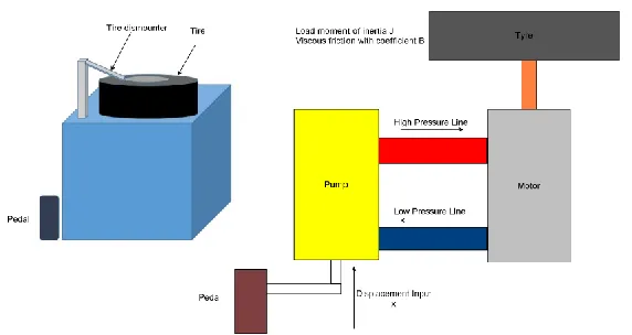
Figure 1 shows the design of the hydraulic based tire changer. The tire changer is controlled by pedal which means an input displacement is entered using this pedal. This displacement is an input to the pump and the pump injects a hydraulic oil to the motor and the motor rotates the tire with an output angular speed.
Figure 1 Hydraulic based tire changer
The hydraulic motor is controlled by the amount of oil delivered by the pump. By mechanically changing the pump stroke, the oil delivered by the pump is controlled. Like in a DC generator and dc motor, there is no essential difference between hydraulic pump and motor. In a pump the input is mechanical power and output is hydraulic power and in a motor, it is vice versa.
Let
qp Rate at which the oil flows from the pump
qm Oil flow rate through the motor
q Leakage flow rate
qc Compressibility flow rate
x Input stroke length
θ Output angular displacement of motor P Pressure drop across motor
The rate at which the oil flow from the pump is proportional to stroke displacement, i.e.
q
p
x
.Oil flow rate from-the pump,
1p p
q K x
Where
3
The rate of oil flow through the motor is proportional to motor speed, i.e.
.
m
d q
dt
. Oil flow rate through motor,
2m m
d
q K
dt
Where
Km = Motor displacement constant.
All the oil from the pump does not flow through the motor in the proper channels. Due to back pressure in the motor, a slices of the shape flow from the pump leaks back past the pistons of motor and pump. The back pressure is the importance that is built up by the hydraulic flow to overcome the hostility of free movement offered by load on motor shaft.
It is usually assumed that the leakage flow is proportional to motor pressure, i.e. qi ∝P.
Leakage flow rate,
3i i
q K P
Where
Ki = Leakage flow rate constant.
The back pressure built up by the motor not only causes leakage flow in the motor and pump but oil in the lines to compress. Volume compressibility flow is essentially proportional to pressure
and therefore the tariff of flow is proportional to the rate of innovations of pressure, i.e. c
dP q
dt
Compressibility flow rate,
4c c
dp
q K
dt
Where
Kc = Coefficient of compressibility.
The rate at which the oil flows from the pump is given by sum of oil flow through the motor, leakage flow rate and compressibility flow rate.
p m i c
q
q
q
q
Substituting Equation (1), (2), (3) and (4) from above Equations, we get
5p m i c
d dP
K x K K P K
dt dt
4
The torque Tm developed by the motor is proportional to pressure drop and balances load torque.
Hydraulic motor torque,
Tm = Kt P (6)
Where
Kt is motor torque constant.
The load has a moment of inertia J and viscous friction coefficient B, Then
Load Torque
2
2 7
l
d d
T J B
dt dt
Hydraulic power input
= qmP (8)
Substituting Equation (2) into eqn. (8), we get
Hydraulic power input 9
Mechanical power output 10
m m
d
K P
dt d T
dt
Substituting Equation (6) into Equation (10), we get
Mechanical power output K Pt d 11
dt
If the losses of the hydraulic motor are neglected, then the mechanical power output is equal to hydraulic motor input.
12m t
d d
K P K P
dt dt
From Equation (12), it is clear that
K
m
K
t.Hence we can write
m t m
T
K P K P
Since the load torque equals motor torque, T m = T l
2
2 13
m
d d
K P J B
dt dt
5
22 14
m m
J d B d
P
K dt K dt
Differentiating Equation (14) w.r.t time, we get
3 2
3 2 15
m m
dP J d B d
dt K dt K dt
Substituting for P and dP/dt to Equation (5), we get,
2 3 2
2 3 2 16
m i c
m m m m
dx d J d B d J d B d
Kp K K K
dt dt K dt K dt K dt K dt
Taking Laplace transform we get,
2
2
17 p
c i c m i
m m m
K s
X s K J K J K B K K B
s s s
K K K
The speed become
s s
s 18
Substitute Equation (20) into Equation (19) yields:
2
2
19 p
c i c m i
m m m
K s
X s K J K J K B K K B
s s
K K K
Rearranging Equation (19) the final transfer function becomes:
2
20X s s
K s s Where p m c i c c K K K K J
K J K B
K J 2 m i c
K K B
K J
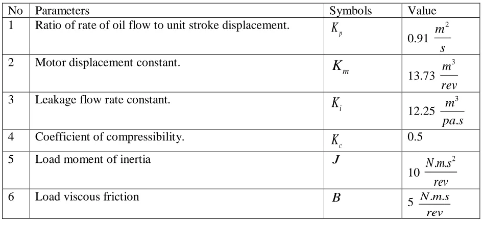
6 Table 1 shows the parameters of the system.
Table 1 System parameters
No Parameters Symbols Value
1 Ratio of rate of oil flow to unit stroke displacement.
p
K
0.91
2 m
s
2 Motor displacement constant.
m
K
13.73
3 m rev
3 Leakage flow rate constant.
i
K
12.25
3
. m pa s 4 Coefficient of compressibility.
c
K
0.55 Load moment of inertia J
10
2
. .
N m s rev
6 Load viscous friction B
5 N m s. .
rev
The transfer function of the tire remover system is
22. 25 50
5 s
X s s s
The state space representation becomes:
25 50 1
1 0 0
0 2.5
x x u
y x
3. Proposed Controllers Design
3.1Augmentation Based H infinity and H2 optimal Synthesis Controllers Design
7
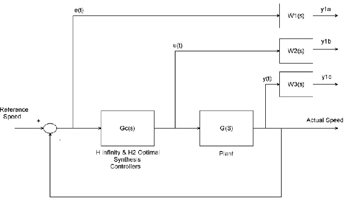
Figure 2 Tire changer with H infinity and H2 optimal synthesis controllers
One may marvel why we need to utility three weighting functions in Figure 2. First, we memo that the weighting functions are, respectively, for the three signals, namely, the error, the input, and the output. In the two-port state space structure, the output vector y1 = [y1a, y1b, y1c] T is not used directly to construct the control signal vector u2. We should understand that y1 is actually for the control design characteristic measurement. So, it is not strange to include the filtered "input signal" u(t) in the "output signal" y1 because one may requirement to measure the sovereignty energy to assess whether the designed controller is good or not. Clearly, Figure 2 represents a more general picture of H infinity and H2 optimal synthesis control systems. The weighting functions can also be regarded as filters. This type of frequency-dependent weighting is more practical. We will bazaar next that, given the weighting transfer functions, we can design an H infinity and H2 optimal synthesis controllers by using the impression of the augmented state space model.
The weighting function W1(s), W2(s), and W3(s) are chosen as
1 2 3
100
0.1 0.1
100 1
s
W s W s W s
s
The H infinity synthesis controller become
2
3 2
6.24 29.39 48.43 25.22 55.46 0.5521
cH
s s
s G
s s
The H2 optimal synthesis controller become:
2
2
3 2
0.8158 20.39 40.79 25.05 51.26 0.5101
cH
s s
s s s
G
8 4. Result and Discussion
4.1Comparison of the Tire Changer with H and H2Optimal Synthesis’s Controllers for a Desired Step Reference Input
The Simulink model for the tire changer with H and H2optimal Synthesis controllers for a desired step input speed is shown in Figure 3 below.
Figure 3 Simulink model for the tire changer with H and H2optimal Synthesis controllers for a desired step input speed
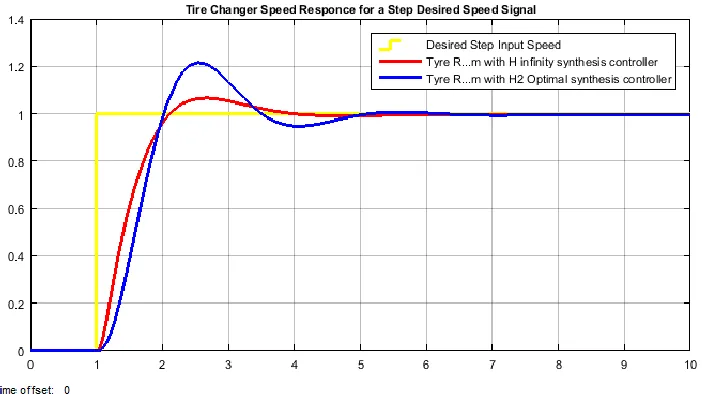
For a desired speed change from 0 to 1 rev/m input, the tire changer speed response simulation is shown in Figure 4 below.
Figure 4 Tire changer speed response simulation for a step input
For operating the system with 1 rev/min, the simulation result shows that the tire changer with H synthesis controller have a better rise time, smaller percentage overshoot and improved settling time than the tire changer with H2optimal synthesis controller.
9
The Simulink model for the tire changer with H and H2optimal Synthesis controllers for a desired random input speed is shown in Figure 5 below.
Figure 5 Simulink model for the tire changer with H and H2optimal Synthesis controllers for a desired random input speed
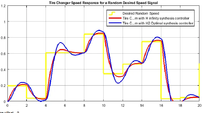
For a desired random speed change from 0 to 1 rev/m input, the tire changer speed response simulation is shown in Figure 6 below.
Figure 6 Tire changer speed response simulation for a random input
For operating the system with a random speed, the simulation result shows that the tire changer with H synthesis controller have track the random input speed with small overshoot than the tire changer with H2optimal synthesis controller.
5. Conclusion
10
used to improve the tire changer speed of rotation. Comparison of the proposed controllers have been analyzed and simulated using two reference inputs (step and random). Finally the comparative simulation results proved the effectiveness of the proposed tire changer with H synthesis controller in improving the settling time and percentage overshoot.
Reference
[1].Melku Abebe et al. “Design of Tire Changer” International Journal of Engineering Trends and Technology, Vol. 64, No. 1, pp. 8-23, 2018.
[2].Sutar Gururaj et al. “Study and Analysis of Tire Changing Machine Components” International Research Journal of Engineering and Technology (IRJET), Vol. 04, Issue 06, 2017.
[3].Pornima T. et al. “Machine for Tire Removing and Fitting on Rim of Wheel: A Review” International Journal for Scientific Research & Development, Vol. 4, Issue 05, 2016. [4].Hardik V et al. “A Literature Review on Design and Analysis of Tyre Envelope Expander
for Tyre Retreading Process” International Journal Of Engineering Innovation And Scientific Research, Vol. 1, Issue 2, pp. 10-13, 2015.