CSEIT184647 | Published – 08 May 2018 | May-June 2018 [ (4 ) 6 : 243-249 ]
National Conference on Engineering Innovations and Solutions (NCEIS – 2018)
International Journal of Scientific Research in Computer Science, Engineering and Information Technology
© 2018 IJSRCSEIT | Volume 4 | Issue 6 | ISSN : 2456-3307
1
Speed Control of Vehicle in Accident Zone
A Shabaz Khan
1, Chethan M N
1, Akash O
1, Ch. Rakesh Singh
1, D V Manjunatha
2 1UG Students, Department of ECE, AIET, Mijar, Karnataka, India2Sr. Prof. & HOD, Department of ECE, AIET, Mijar, Karnataka, India
ABSTRACT
In today’s world increase in population and life standards of people leading to rapid increment in the density of vehicles with enhanced speed and extra features. The craze in drivers makes them to drive the vehicles in high speed in all the regions (school zones, hospitals, bus stops etc.). The number of accidents is increasing due to which people are losing life and may be leading to permanent disabilities. In order to avoid all these problems the government authorities has taken several necessary steps like, sign boards, wearing helmet, speed humps etc. The rules and regulations are not effectively followed or not been observed by the drivers. If there is a system that intimates the driver about the rules and also control the vehicle in these sensitive areas. In this paper implementation of the system is proposed using two methods such as RF communication and Geo-fencing. The proposed system is an attempt to control the speed of the vehicle. The system is designed with software and hardware to intimate the driver about the speed of the area in which the vehicle is currently located. The main focus of this work is to provide safety and precaution to the driver as well as to the passengers and to avoid the accidents. In RF communication method RF transmitter is placed at accident zones and RF receiver placed in the vehicle will communicate using electromagnetic waves. The microcontroller is the brain of the system that activates the particular action corresponding to the received signal (represents the speed limit of the area). The implementation part is done by using geo-fencing technology to overcome from the drawbacks which are encountered in RF technology. Geo-fencing is a virtual geographical boundary defined by GPS that activate software solution when the device is tracked. Geo-fencing delivers the range of efficiency, utilization and safety benefits.
Keywords: RF transmitter and receiver, speed limits, sign boards, accident zones, Geo-fencing.
I.
INTRODUCTION
Over the decades most of the road accidents are due to over speeding of vehicles. The road accidents are increasing year after year due to more number of vehicles. The youthfulness in drivers makes them to drive the vehicle very rashly, which is the craze of every driver.Overspeeding in accident zones (like school areas, hospitals and crowded areas etc.) and also the speed humps are major cause for the accidents. In addition to that drivers often can’t recognize the appearance of unmarked speed
to traffic as well as accidents due to collision will be controlled. Due to advancement in technology, it is possible to control or set the speed of vehicle at a given limit on the roads like highways, express high ways and any area where the speed limit is desired by the authority. The system is applicable for any speed limit which can be set or controlled as per the requirement. The system is implemented using two methods, one is using RF communication system and
the second is using geo-fencing. In RF
communication, the system consists of transmitter and receiver. The transmitter is installed at the road side where the speed of the vehicle has to be controlled. The transmitter transmits the speed limit of that area is received by the receiver which fixed in the vehicle. The received speed limit is fed to microcontroller which activates the necessary action to control the speed of the vehicle. The RF transmitter and receiver communicates using radio frequency signal.
In geo-fencing, the geo-fence apps and tools monitor when mobile devices or other physical objects enter or exit an established geo-fenced area and provide an alerts or notifications to the controlling system. These alerts can be in form of text messages, e-mail notifications, phone calls or similar means of communication. Depending on the notifications, the speed of the vehicle is controlled.
II.
METHODS
The paper discuss about the two different methods to implement the objectives (providing prevention and precaution in accident zone). The two methods are RF communication system and Geo-fencing system. These are two different domains which are used to achieve the same goals. The RF communication method deals with the transmitter and receiver section with an encryption and decryption to provide security to the information to be transmitted. The information transmitted is the speed limit of the particular area, where the speed of the vehicle has to be controlled. The Geofencing method consists of
server and client. The server works with a principle of location based service and exchanges of information takes place with the push and pull method. The client refers to the vehicle that its speed has to be controlled to the speed defined for that geo-fenced area.
A. RF Technology
i. RF Transmitter
RF transmitter module shown in Fig. 1, is connected to a microcontroller through an encoder it transmits the radio wave signals. The transmitter works with Atmega328 microcontroller that transmits the data in parallel form to the encoder. The transmission range of an antenna is affected by the environmental factors like noise, harmonic and multi path data reception. The high range of transmission can be achieved by improving efficiency of antenna.
The encoder HT12E has 12 pins, in which 8 pins are address pins and other 4 pins are control pins connected to the microcontroller. The control pins are represented as D0 to D3 and address pins are from A0 to A7 and also the Transmission Enable (TE) pin is connected to ground or it can be left open. The data of encoder from analog pins has to match with decoder. The 1.1 MΩ resistor is connected across encoder to provide external resistance for the oscillator.
Figure 1.Block diagram of transmitter module
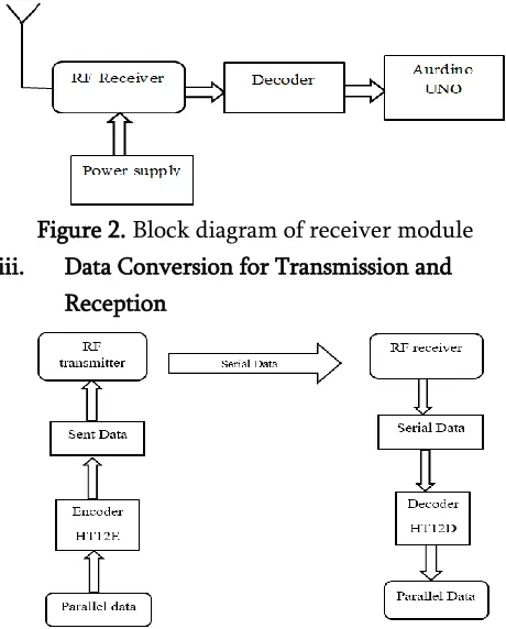
ii. RF Receiver
compared to super generative receiver. The quality of reception is high and also power design is complicated.
The data which is transmitted through the air medium is in analog form with amplitude modulation. The HT12D decoder is used to demodulate the original signal by providing additional bits so that the data can be recovered even if it is affected by noise. Here the decoder also has four control pins and eight address pins. The demodulation takes place only when the address pins of encoder and decoder matched. When the VT pin is high and blinking of LED indicates that the receiver has received the signal. The resistance of 51KΩ is used as an external resistance for oscillator in decoder.
Figure 2. Block diagram of receiver module iii. Data Conversion for Transmission and
Reception
Figure 3. Data transmission of RF Tx and Rx The transmission of data shown in Fig. 3 takes place between the transmitter and the receiver through the free space, so the air acts as a medium to transfer data. There is physical connection existing between transmitter and receiver. First the data is in parallel form is converted to serial form, data transmission in free space in forms of serial manner, and in the
receiver part these data are converted to a parallel form. These conversions of data take place in encoder and decoder, these conversions of data from one form to another form is explained below.
The RF technology has better prospective in other communication systems but in speed control system it has few drawbacks like one way communication, transmission range, installation and maintenance. The drawbacks of the system can be overcome by the Geo-fencing technology which is explained in the below section.
B. Geo-fencing
The implementation of Geofencing is to track, monitor and control the speed of vehicles. Firstly, the particular area has to be created as a geo-fenced area where the speed of the vehicle is to be controlled. The areas which are taken into consideration are school zone, accident zone, hospitals. The Fig. 4 shows the block diagram of the proposed system using geo-fencing. The inclusion of a microcontroller makes the system to be a stand-alone, which has capability to take decisions to keep the system functioning properly. The system consists of GPS and GSM modules.
server. The server is created to maintain the database. The database contains GPS values of the geo-fenced locations and the corresponding speed limits of those locations and the unique identity of the vehicles. When the vehicle enters the geo-fenced area the server compares GPS values of the location to which vehicle entered with the values which already stored in the server. The server sends a particular speed limit of that area only when the compared values are matched. The speed limit of the particular area is fed to microcontroller through GSM.Then the microcontroller takes necessary action to control the speed of the vehicle. The LCD display is used to display the particular speed limit of that area.
III.
RESULTS AND DISCUSSIONS
In this section the results are discussed for two different methods they are RF communication system and Geo-fencing. The hardware and software are implemented in prototype. This chapter shows the working of prototype and also the result obtained.
A. Results of RF Technology
The RF communication system consists of transmitter and receiver, which communicates with one another using pre-defined radio frequency range.
Figure 5. A snapshot of the RF communication system
The different speed limits are set in the transmitter part for different speed limit areas. The speed limit of particular area is transmitted in the form of both analog as well as digital forms. Receiver part is the controlling unit of the prototype. In non-speed limited areas the speed of the DC motors can be varied as per the user requirement. Potentiometer
acts as an accelerator in which the speed can be increased or decreased.
Figure 6. Testing of speed level-1
The Fig.6 shows the testing of speed level-1. In speed level-1 the maximum allowable speed is 30Kmph. If the user actual speed is greater than the allowable speed then the actual speed is reduced to 30kmph or below even though the user accelerates the vehicle is in a specified speed.
Figure 7. Testing of speed level-2
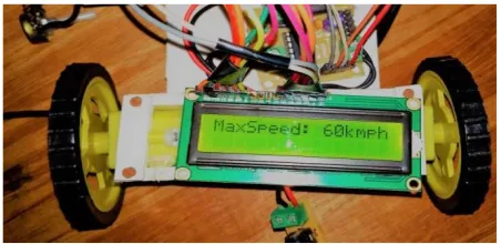
Figure 8. Testing of speed level-6
The Fig. 8 shows the testing of speed level-6. In speed level-6 the maximum allowable speed is 180Kmph. If the user actual speed is greater than the allowable speed then the actual speed is reduced to 180kmph or below. Even though the user accelerates the vehicle is in a specified speed.
Figure 9. Testing of speed level-7
The Fig.9 shows the testing of speed level-7. In speed level-7 the maximum allowable speed is 210Kmph. If the user actual speed is greater than the allowable speed then the actual speed is reduced to 210kmph or below. Even though the user accelerates the vehicle is in a specified speed.
B. Results of Geo-fencing Technology
Geo-fencing technology deals with client and server. Here the local host server is used to communicate with client. The channel is established by turning on hot spot of host device and connecting the client and application software installed in the system.
At first when the device in the vehicle turns ON, the Wi-Fi module updates the location of the vehicle by sending the latitude and longitudinal values. The devices which are created in the server are gets activate when it receives the positional value with unique identity number. The below Fig. 10 shows how the devices are activated in the server.
Figure 10. Device activation
Once the device is activated, the client and server are ready to establish communication with each other. In the beginning the reference location is send. The device comes into that reference position when vehicle turns on. The vehicle employs a rotary encoder to calculate the speed of the vehicle the speed will set in the vehicle by evaluating the feedback speed.
When the client is moving the latitude and longitude position of the vehicle gets updated. For every two seconds the client sends a location update. This data is transmitted through the wireless channel created from the mobile hotspot and the data send to the server. In server it checks the corresponding speed limit of that location and it is transmitted back in the same way.
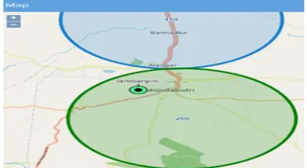
Figure 11. Snapshot of a device in reference position
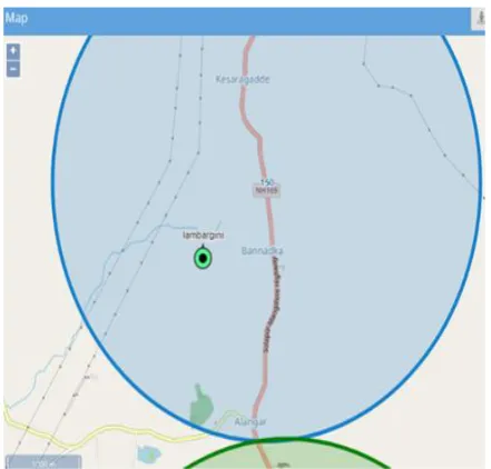
vehicle is reduced. The Fig. 12 shows the different speed zone in which vehicle is moved.
Figure 12. Image of a device moving to different speed zone
IV.
CONCLUSION AND FUTURE SCOPE
The different techniques and methods to control the speed of vehicle in accident zones are discussed in literature. The techniques used so far have the drawbacks which are complicated in implementation part and to meet the real time applications. The important aspect is that even the gap has to be built in terms of technology. The objectives can be met by using the geo-fencing technology. The proposed system is much more accurate and easy to implement in the real time. As the different accident zones like schools, hospitals, public areas and sensitive areas are marked in the traccar software. The additional information can also be provided for driver like nearby fuel stations, hospitals etc. there are some more additional features in this particular system like providing the location of the vehicle to the server and even vehicle tracking can be done.
The proposed work has great advantage and also it has some limitations, and every limitation is subject for research there are various methods to alert the driver and control the speed of the vehicle, a lot of research can be conducted in this field. The
geo-fencing technology is the new method to alert and respond according to it in the vehicle as the geo-fencing technology has various other futures which are required for the driver and also for the vehicle. The additional features are mentioned in the implementation.
The proposed work has a great application in the smart city. The most of smart activities is performed by the vehicle through the geo-fencing system. The activities like an alert can be made for no harm area, restricted speed limit area, payment of toll road and tracking vehicle etc.
V.
REFERENCES
1. P Gurusamy, M Anusha, N Devipriya, P Harini, MD Asrar UlHaque C, “Speed control of vehicle by detection of potholes and humps”, IJAREEIE, Vol 5, 1- 2 March 2016. detection dystem”, IEEE 2nd International conference on computational Intelligence & communication Technology, 2016.
4. Marco De Piante, Andrea M Tonello, “RF
architecture for wireless sensor network coverage improvement”, IEEE 5th (ICCE-Berlin) 2015.
5. Anirban Chowdhury, JhulanKumar, Abhra
Majumder, “A solution to speeding related problem in road vehicles using RFID tags”,
International Conference on control,
Instrumentation, Energy &Communication (CIEC), 2014.
7. Deepa B Chavan, Abdul Rahim Makandar, Faizul
Hakeem Khan, Syed AzimuddinInamdar,
“Automatic vehicle speed reduction system using RF technology”, Journal of Engineering Research and Applications, Vol 4, April 2014.
8. Nishanth P.R, Ancy John, “Intelligent vehicle with accident prevention”, NCTIMEMIC, Vol 3, 2017.
9. Juan Martin Raya Bahena, Carlos A Viles Cruz, Arturo Zuniga Lopez, Andres Ferrera – Ramirez, “Speed booms detection for a ground vehicle
with computer vision”, Advances in
Mathematical and Comutational methods. ISSN: 1792-6114.