DOI : https://doi.org/10.32628/CSEIT1952271
A Comparative Study on Load-Frequency Controllers of a
Five-Area Interconnected Power System
Dao Thi Mai Phuong
Department of Electrical Engineering Technology, Hanoi University of Industry, Hanoi, Vietnam
ABSTRACT
The crucial objectives of load-frequency control (LFC) to a multi-area interconnected power system are to maintain the system frequency at a nominal value (50 Hz or 60 Hz) and the tie-line power flows at predetermined values. Based on tie-line bias control strategy, conventional regulators, such as I, PI and PID, were initially used for solving the LFC problem. Due to the complexity, nonlinearity and uncertainty of a multi-area power system in practice, the conventional regulators may not obtain the control performances good enough to bring the network back to the steady state as soon as possible. Meanwhile, intelligent controllers, such as fuzzy logic (FL)-based controllers, are able to completely replace these conventional counterparts. The superiority of the FL-based LFC controllers over the conventional ones for a typical case study of five-area interconnected power grids is validated in this paper through numerical simulations implemented in Matlab/Simulink package. It should be apparent from this comparative study that the LFC controller based on FL technique is a feasible selection in dealing with the LFC problem of a multi-area power network.
Keywords: LFC, Five-Area Interconnected Power System, Conventional Regulator, Intelligent Controller, FL
I. INTRODUCTION
Together with voltage, frequency is a highly important parameter in power system operation and control. The frequency of an electric power grid is a systematic parameter, which is required to be a constant value at any point of the network. The nominal value of the electric power network frequency is 50Hz for most countries in the world, except in the US and Western of Japan the network frequency is 60Hz. It is an undeniable fact that the network frequency changes over time depending on load characteristic which is always varying in an electric power grid. Unacceptable system frequency deviations from the nominal value affect a lot of devices, causing unstable and uneconomic operation
of an electric power grid [1-3]. Therefore, it is necessary to establish robust load frequency control (LFC) strategies to control the automatic generation in an interconnected power system [1]. In general, the main roles of these control strategies are to maintain the frequency and tie-line power to ensure the optimal and economical generation in the power network.
performances are very poor, such as high overshoots and long settling times which strongly affect the operation and stability of the system [2], [4]. To overcome these drawbacks, intelligent controllers using modern control techniques, e.g., fuzzy logic (FL) have been investigating heavily in recent years. By using the FL controllers, the above control performances are significantly improved in order to achieve the desired control performances [4-5].
In this paper, different controllers, namely I, PI, PID, and FL are successfully investigated and compared to demonstrate the effectiveness of the tie-line bias control strategy used in the load frequency control problem. A five-area interconnected thermal power system using non-reheat turbines is mathematically built to implement the above controllers. Via the evaluation of simulation results obtained by using Matlab/simulink software, FL controllers are selected to be a more ideal regulator of this control problem. In the next section of this paper, we introduce the analysis of a five-area interconnected power system controlled by the tie-line bias control strategy. The following sections present the application of different controllers, namely conventional and intelligent controllers, based on the tie-line bias control scheme. The numerical simulation results and discussions will also be given in the last two sections of this paper to evaluate and choose the most effective controller to stabilize the frequency in an electric power grid.
II. MATHEMATICAL MODEL OF A FIVE-AREA INTERCONNECTED POWER SYSTEM
Establishing a mathematical model of a control system is the first step in designing a control strategy for any plant. In fact, this procedure normally includes several sub-steps, such as identification, mathematical approximation and optimization. This is an important step in order to ensure the accuracy and efficiency of the control system designing.
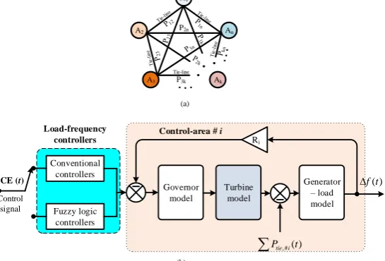
Practical interconnected electric power grids are highly complicated and it is impossible to create a mathematical model for all power networks. In this paper, a five-area interconnected power system is selected as a typical case study. Figure 1 (a) shows a power system including five areas interconnected through tie-lines. Here, each area or control-area is assumed to be connected with all other areas, so that the tie-line power flows can be easily exchanged among power stations. It is generally supposed that each control-area includes four main elements, i.e. a governor, a turbine, a generator and load. They are presented in Figure 1(b) for the ith control-area. The transfer functions in Laplace domain for these components are given in Table 1 [1, 2, 10].
Table 1: Transfer functions of each basic component of a control-area
Governor Turbine Generator-load
𝐺𝑔𝑖(𝑠)
= 1
𝑠. 𝑇𝑔𝑖+ 1
𝐺𝑡𝑢𝑟𝑏𝑖𝑛𝑒
1
𝑠. 𝑇𝑡𝑖+ 1𝑖
𝐺 𝐾𝑝𝑖
𝑠.𝑇𝑃𝑖+1𝑃
To describe the control plant for the whole system, the following state-space model can be used:
𝑋̇ = 𝐴. 𝑋 + 𝐵. 𝑈 + 𝐹. 𝐷 (1)
where,𝑋𝑇 = [Δ𝑓𝑖 Δ𝑃𝐺𝑖 Δ𝑃𝑉𝑖 Δ𝑃𝑡𝑖𝑒,𝑖], 𝑖 = 1,2,3,4,5
is the static variable, 𝑈𝑇 = [Δ𝑃𝐶1 Δ𝑃𝐶2 Δ𝑃𝐶3Δ𝑃𝐶4Δ𝑃𝐶5] is the control variation,
and 𝐷𝑇 = [Δ𝑃𝐷1 Δ𝑃𝐷2 Δ𝑃𝐷3Δ𝑃𝐷4Δ𝑃𝐷5] is a vector of
the load changes. Here, the deviation of the tie-line power of the ith control-area is calculated as follows:
Δ𝑃𝑡𝑖𝑒,𝑖(𝑠) = 2𝜋
𝑠 ∑ 𝑇𝑖𝑗 0(Δ𝐹
𝑖(𝑠) −Δ𝐹𝑗(𝑠))
5 𝑗=1 𝑗≠𝑖
(2) where 𝑇𝑖𝑗0 andΔ𝐹𝑖(𝑠) are the synchronizing factor of
the tie-line and the deviation of the frequency of the
𝐴𝐶𝐸𝑖(𝑠) =Δ𝑃𝑡𝑖𝑒,𝑖(𝑠) + 𝐵𝑖.Δ𝐹𝑖(𝑠).
(3) Using the above control signal, ACEi(s), each control-area might need only one regulator for both goals: elimination of the network frequency deviation and maintenance of the power flow exchange in the
tie-Figure 1. Interconnected power system model for LFC problem
(a) Multi-control-area model (b) Main elements of a control-area
III.DIFFERENT LOAD-FREQUENCY CONTROLLERS
3.1. Conventional controllers
Generally, the PID (Proportional – Integral –
Derivative) regulator is a type of conventional controllers suitable for many control problems. The principle of a PID regulator applied to the LFC is integral, derivative gain factors, integral time, and derivative time constants, respectively.
Applying the conventional PID regulator, it is necessary to find an appropriate tuning method for three factors: Kpi, KIiand Kdi. In this paper, the Ziegler-Nichols method to tune these coefficients has been employed. By applying this method, first, the integral and derivative gains are set to be zero, then, the proportional gain is tuned to reach the value at which the output of the system begins fluctuating. In the second step, the derivative gain will be defined with the tuned proportional gain above to make sure the transient performance. In the last step, the integral gain will be finally fixed with the other factors chosen above to ensure the steady state characteristic of the control system. Due to the sensitivity of the derivative factor, in many control systems, a PID regulator can be replaced with a PI one and the control performances are quite good enough.
3.2 Fuzzy logic controllers
The interconnected power system is actually characterized by a number of nonlinearities and uncertainties, making the design of an LFC controller highly challenging. Besides, the LFC controllers applying the conventional regulators as mentioned earlier may not be able to obtain the good control
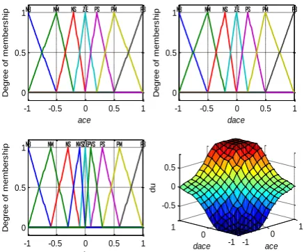
Figure 3: Degree of membership functions and the 3D surface of the proposed FL controller
Let us consider a FL controller which is used for the ith
control area in the given power system as shown in Figure 2. Based on the tie-line bias control scheme, there are a total of five FL controllers used in our control system. For each FL controller, as depicted in Figure 2, it has been fed by two input signals, ace and the acceleration of ace, dace, relating to ACE and the derivative of ACE as follows:
𝑎𝑐𝑒𝑖(𝑡) = corresponding to ACE and the derivative of ACE. The output of the given controller is du relating to the control signal of the ith area, Δ𝑃𝑟𝑒𝑓_𝑖, by the
proportional factor Kui and the summation (or integral) of dU (see Figure 2). In general, each FL controller is an input/output static nonlinear mapping and thus the principle of this FL controller can be
is clear the following equations can be deduced:
𝑈𝑖(𝑡) = 𝐾𝑢𝑖. 𝑢(𝑡) = 𝐾𝑢𝑖[ The equation (9) reveals that the working principle of the FL-based FLC controller is based on the PI regulator. Hence, it is reasonable to define this type of FL controller as a PI-FL controller.
Basically, there are three processes of a PI-FL controller: fuzzification, evaluation of control rule base, and defuzzification, as plotted in Figure 2. For the control rule base of the above FL controller, a 49-rule base is used in the present work. This 49-rule base designed is based on the understanding of the control system in order to minimize the frequency and tie-line power flow changes. A full rule base is illustrated in Table 1 with seven MFs for two inputs ace(t) and dace(t) and nine MFs for the output du(t).
Table 1: Rule base for the proposed FL controller
NB – Negative Big, NVS-Negative Very Small, NM –
Negative, NS-Negative Small, ZE – Zero, PVS- Positive Very Small, PS-Positive Small, PM-Positive Medium, PB-Positive Big
In this design, the MAX-MIN composition is used in which each output, MF, is resulted by a MIN operator.
Meanwhile, a MAX operator has been used for the corresponding FL output. Also, this operation will be illustrated in Figure 3 as the 3D membership surface. To verify the effectiveness of this control strategy, the next section will give the simulation processes and results obtained using Matlab/Simulink package.
IV. NUMERICAL SIMULATION RESULTS
In this section, to implement the simulation of the power system based on the tie-line bias control strategy corresponding to the Figure 3 illustrated earlier, four simulation cases are considered, namely I, PI, PID, and FL controller. In order to evaluate and compare different LFC controllers, a condition of load changes is fed to all simulation cases
𝐷𝑇= [Δ𝑃
𝐷1 Δ𝑃𝐷2 Δ𝑃𝐷3Δ𝑃𝐷4Δ𝑃𝐷5]
= [2(%)1(%)1.2(%)1.5(%)1(%)] (9)
where Δ𝑃𝐷𝑖is the load change in the area ith. Our
control objective is to regulate the state vector 𝑋1𝑇 =
[Δ𝑓𝑖 Δ𝑃𝑡𝑖𝑒,𝑖] which needs to be converged toward the
zero-steady state 𝑋0𝑇 = [00] with the best
performance characteristics, such as small overshoots and short settling times. Simulation results performed in Matlab/Simulink environment version 2015a, have been obtained as plotted in Figures 4 – 9.
Figure 4. Frequency deviations of the first and the fifth area using conventional regulators
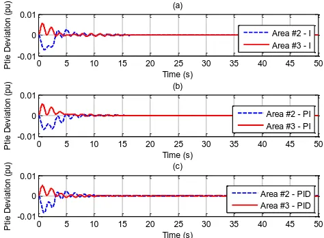
Figure 5. Tie-line power deviations of the 2nd and 3rd
area
Figure 6. Frequency deviations of five areas using FL controllers
Figure 4 illustrates the frequency deviations of the 1st
and 5th areas, corresponding to the application of I, PI,
and PID controllers in the given control system. Figure 5(a), 5(b), and 5(c) show the tie-line power deviations of the 2nd and 3rd areas, for three cases: I, PI,
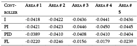
the frequency change error between I-PID controllers is the smallest, whereas the counterpart of I-FL controllers is the largest. Furthermore, to demonstrate numerically the obtained results, Table 2 and Table 3 represent the comparison for all cases. From these two tables, it is clear both the overshoot and settling time of the FL controller are much better than the those of the conventional controllers. These results lead to the removal of the worst case using the integral controller, and the selection of the most effective case using the FL controller for the control system under this study.
TABLE 2: THE COMPARISON OF THE FIRST OVERSHOOT, IN PU
TABLE 3: THE COMPARISON OF THE SETTLING TIMES, IN
SECOND,WITH THE GIVENTOLERANCE OF 0.1% CONTROLLER AREA #
Figure 7. Comparison of the LFC controllers under the present study
V. CONCLUSIONS
This paper investigated a comparative study of different LFC controllers for a typical case of five-area electric power grids. A type of FL controllers has been evaluated in comparison with the conventional counterparts including I, PI and PID regulators. Simulation results and analyses claimed that the FL controller is a perfect choice, achieving better control performances for solving the LFC problem of a multi-area interconnected power system. The difficulties of tuning method selection and/or dealing with the uncertainties and nonlinearities of the network have been able to be efficiently solved when applying the FL-based LFC controllers. Hence, it is feasible to apply this intelligent LFC controller instead of using the conventional counterparts. Future work arising from this study is that it should be necessary to determine an appropriate fuzzy rule base to obtain the desirable control performances for a practically electric power grid.
[1]. Leonard L. Grigsby. Power system stability and control. 3rd edition, CRC Press, 2016.
[2]. Jizhong Zhu. Optimization of power system operation. John Wiley & Sons, 2016.
[3]. A. Moeini and I. Kamwa. Analytical Concepts for Reactive Power Based Primary Frequency Control in Power Systems, IEEE Transactions on Power Systems, vol. 31, no. 6, pp. 4217-4230, Nov. 2016.
[4]. Patricia Melin, Oscar Castillo, Janusz Kacprzyk, Marek Reformat, William Melek. Fuzzy logic in
intelligent system design: Theory and applications. Springer, 2017.
[5]. K. Vinoth Kumar. Neural networks and FL. S. K. Kataria & Sons, 2009.
[6]. J. Liu, Q. Yao, Y. Hu. Model predictive control for load frequency of hybrid power system with wind power and thermal power, Energy, Vol. 172, 2019, pp. 555-565.
[7]. S. Hamid Shahalami, D. Farsi. Analysis of Load Frequency Control in a restructured multi-area power system with the Kalman filter and the LQR controller, AEU - International Journal of Electronics and Communications, Vol. 86, 2018, pp. 25-46.
[8]. C. Zhao, U. Topcu, N. Li and S. Low. Design and Stability of Load-Side Primary Frequency Control in Power Systems, IEEE Transactions on Automatic Control, vol. 59, no. 5, pp. 1177-1189, May 2014.
[9]. Ş. Sönmez, S. Ayasun and C. O. Nwankpa. An
Exact Method for Computing Delay Margin for Stability of Load Frequency Control Systems with Constant Communication Delays, IEEE Transactions on Power Systems, vol. 31, no. 1, pp. 370-377, Jan. 2016.
[10]. Mohamed M. Ismail, Ahmed F. Bendary, Load Frequency Control for Multi Area Smart Grid based on Advanced Control Techniques, Alexandria Engineering Journal, Volume 57, Issue 4, 2018, Pages 4021-4032.
[11]. H. Yousef. Adaptive fuzzy logic load frequency control of multi-area power system, International Journal of Electrical Power & Energy Systems, Vol. 68, 2015, pp. 384-395.
Dao Thi Mai Phuong received Msc degree
in Automation and Control at Hanoi
University of Science and Technology, in 2010. She received the PhD degree in
Control Science and Engineering at Hunan University,
in 2017. She is working as a lecturer and researcher at Hanoi University of Industry in Hanoi, Vietnam. Her research interests include smart grids, intelligent control, control theory and applications.
Cite this article as :
Dao Thi Mai Phuong, "A Comparative Study on Load-Frequency Controllers of a Five-Area Interconnected Power System", International Journal of Scientific Research in Computer Science, Engineering and Information Technology (IJSRCSEIT), ISSN: 2456-3307, Volume 5 Issue 2, pp. 1019-1025, March-April
2019. Available at doi :
https://doi.org/10.32628/CSEIT1952271