International Journal of Research in Advent Technology, Vol.2, No.2, February 2014
E-ISSN: 2321-9637
Setting Up the Organisation Standard in CAD Modeling
Environment
Deshmukh Akshay Vasantrao
S.Y.M.Tech Mechanical-PLM S.G.G.S.I.E.T., Namded
Nanded, India
Salve Kapil Babanrao
Asst. Professor J.D.I.E.T. Yavatmal
Yavatmal, India [email protected]
Ghatole Gunwant Arvindrao
F.Y.M.TechHeatPower SSPACE, Wardha
Wardha, India
ABSTRACT
So many Mechanical industries in India are introducing IT in their manufacturing process to reduce the time lag of launch a new product into the market. Since, the most industries are using CAD softwaretoprepare their product virtually instead of using the pencil, eraser and big drawing sheets. As we know that 80% time is waste in the design process. Also prepare drawing of part on such a huge sheet is quite difficult compared to using CAD software, because it reduces the time to prepare drawing of the part due to the availability of different features directly within the software. CAD software provides ease to prepare model virtually and also helpful to visualize the model before it is produced. Use of CAD software since reduces very much time in whole lifecycle of product. Most of the industries use the different kinds of CAD software according to their need. They were facing so many problems while designing the part also there can be possibility to introduce automation for the particular process. Those will become beneficial for the reduction of the design cycle time. In the paper I have decided toimplement the customization of CAD softwareCreo Elements/Pro, formerly known as Pro/ENGINEER, an integrated 3D CAD/CAM/CAE solution created by Parametric Technology Corporation (PTC).This will beneficial to reduce the time of designer while assembling a product.
Keyword: CAD customization, Proprogramming, Protoolkit
INTRODUCTION
Creo Elements is widely used software in the industries for preparing their drawings and models. Since, I have decided to provide automation facility in this software for the reducing the time of designer while designing. In customization I have decided to deal with assembly section of the Creo Elements, as industryisspendinghuge amount of time in removing constrains manually for huge number of components assembly which can be minimized. To minimize it I am preparing the ProToolkit application which will automatically remove constrains of component and fix itwith the help of batch mode.
1.1 Creo Elements
Pro/ENGINEER is the first commercial CAD system entirely based upon the feature-based design and parametric modeling philosophy. Creo Elements/Pro (formerly Pro/ENGINEER), PTC's parametric, integrated 3D CAD/CAM/CAE solution, is used by discrete manufacturers for mechanical engineering, design and manufacturing. 1.2 PTC Creo Elements Customization
Customization is defined as the configuration of products and services that meet customer’s individual needs. Customization research has been developed in the fields of product design and operations management to develop ways in which goods and services can be adapted to individual standards. [3]
To customize Creo Elements variousprogrammingtechniques are provided by PTC which are listed below:
a) ProToolkit
C programming based Application Programming Interface commonly known as API for Creo.
b) J-Link -Java programming interface for Creo.
c) Visual Basics Programming -Easy creation of user interfaces.
d) Web Link-JavaScript programming interface for Creo.
1.3Creo Elements/Pro TOOLKIT
Creo Elements/Pro TOOLKIT provides a large library of C functions to provide the external application safe and controlled access to the Creo Elements/Pro database and applications. Creo Elements/Pro TOOLKIT is the primary PTC application programmer's interface (API) for Creo Elements/Pro. [1]
Figure. 1. Working of a Pro/Toolkit application [6] An application that automates feature creation in Pro/Engineer first creates a two-dimensional section based on values input by the user and then performs the three-dimensional feature operation on it. Depending on the program parameters that define the sketch, the two dimensional section could be of any shape.
IIPROBLEM STATEMENT & PRAPOSED SOLUTIONS
The most of time consume of design engineer in setting up organization standard and modeling environment. We found some solution which stated below so that we can save lots of time to setting up organization standard and modeling environment.
So the following are the proposed solutions:
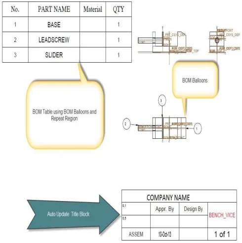
1) Defining standard BOM tables in drawing template with auto updating feature.
2) Modification with help of MS Excel. 3) Modification with help of Pro Programming.
4) Defining standard part with family table feature with help of MS Excel Integration.
So, we are providing a solution by setting up organization standard In a CAD modeling environment.
III CREATION OF BOM TABLE USING REPEAT REGION
The Bill of Material (BOM) lists all parts and part parameters in the current assembly or assembly drawing. The BOM also comprises a breakdown and a summary of the report. The Breakdown section lists what is contained in the current assembly or part. The Summary section lists the total quantity of each part included in the assembly, and is the list of all the parts needed to build the assembly from the part level.
3.1 BOM Balloons
BOM balloons are circular callouts in an assembly drawing that show Bill of Materials information for each component of an assembly view. The information is derived from a report table repeat region that you also specify as a BOM balloon region. Before you can add BOM balloons, you must create the table, add the repeat region, enter the desired report symbols, and designate the BOM balloon
region. When you have done this, you can show BOM balloons on a selected assembly view
Figure. 2. BOM Balloons
BOM balloons usually show an index number, corresponding to a part name in the table. The report symbol for the index number is rpt.index. The report symbol for the part name is asm.mbr.name.
Figure 3 -Drawing Sheet With BOM Balloons Table.
IV-MODIFICATION WITH HELP OF MS EXCEL.
The parametric nature of any component design makes the effective implementation of the designconcept with ease and simplicity using Pro/Engineer. Using parameters and its relationship, the parametricconcept is implemented for designing differentcomponents using Pro/Engineer software throughdifferent interface for automation of them. DetailMethodology of interfacing of Pro\Engineer with Excelsheet is reported in this chapter. Data from Excel istransferred to Pro/ENGINEER via Pro/Program toupdate the solid geometry.
REFERENCES
[1] Creo Elements/Pro 5.0 Creo Elements/ProTOOLKIT User’s Guide February 2011
[2] Horgan, Jack (2004-06-21). "EDA & PLM?"EDACafe.com Contributing Editor. Retrieved 2010-06-15
[3] The human dimension of modular care provision: Opportunities for personalization and customization by Carolien de Blok, Bert Meijboom, KatrienLuijkx, Jos Schols in. J. Production Economics 142(2013) page no.16–26. [4] Collaborative intelligent CAD framework incorporating
design history tracking algorithm by Hyunsoo Lee, JonghyunKimb, Amarnath Banerjee in Computer-Aided Design 42 (2010) page no. 1125–1142
[5] A study of the influence of technical attributes of beginner CAD users on their performance by R. F. Hamadea , H. A. Artailb Computer-Aided Design 40 (2008) page no. 262–272. [6] Integration of Pro/Engineer with Visual C++ using