ISSN 2348 – 7968
Design and Fabrication of a Model Methylpropane Rocket
Thruster
1
S.Tamil Selvan,2V.Saravana kumar,3R.PandyRajan
1Assistant prof.-(-(Aeronautical Engineering Department/Hindusthan Institute of Technology/India) 2Lecturer-(Aeronautical Engineering Department/KarpagamUniversity/India)
3Lecturer-(Aeronautical Engineering Department/KarpagamUniversity/India) ABSTRACT
The rapid growth in demand for spacecraft launch services has spawned a need for a variety of new, innovative, and low-cost propulsion technologies, Advanced, low-cost rocket engine controllers are a critical part of the technology required. Different forms of rocket thrusters are in use, the model rocket thruster developed based on the principle of MPDT. The model rocket uses electrical input with propellant. Numerous designs of thrusters of this type, using various kinds of propellant and operating at different power ranges were developed during this period of time. The most typical design schemes and their operation parameters are presented in the project.
Keywords-Thruster,mpdt,thrust,
I. INTRODUCTION
The working of Model Rocket Thruster works under the concept of Electric Propulsion. The 420V battery is connected with the Thruster as the Energy source through the Timing device. When the timing device operates energy source from the battery transmitted to the thruster. In this Electrical energy is converted into Heat energy.
The Burner is a circular device connected at one end with insulator and free in another end. The insulator which consist of four opening for the supply of propellant(Methylpropane Gas). It also provided with the Spark Plug at the center which is connected with electric supply. Whenever the Electric supply is given to the spark plug , which ignites and mixes with the propellant flow through the openings. Mixing of both Propellant and the spark results in the combustion. The burning of propellant takes place and the Flames will be developed at the rear end of the burner.
II. LITERATURESURVEY
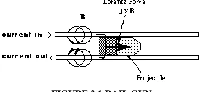
2.1 RAIL GUNS
Drive enough current down one side of two parallel conducting rails, across a conductor that can slide down the rails while maintaining contact, and up the other side and you have a rail gun. The current flowing in the rails create a strong magnetic field between them. The same current flowing across the sliding conductor is the current the magnetic field wants to push away.
ISSN 2348 – 7968
You'll need to added something like a machine gun feeder to supply it with a constant source of sliding projectiles (which we should now call "propellant" since we're using it as a rocket engine) but that's a simple mechanical engineering problem.
FIGURE 2.1 RAIL GUN
2.2MAGNETOPLASMADYNAMIC (MPD) THRUSTERS
Crank the power up on the rail gun high enough and the sliding conductor would vaporize. The engine would still work because the plasma would continue conducting current and be blown out the end of the gun. Flatten and bend one of the rails around in a tube surrounding the other rail and you have an MPD thruster. (For further details about MPD thrusters please check out the MY ELECTRIC ROCKET ENGINE page on this site.)
MPD thrusters are unique among the electric rocket engine fraternity because they are capable of producing thrusts as high as 50 pounds in an engine small enough to fix in a large shoe box. The problem with them is the electrodes wear out from handling all the current and they eat up enormous amounts of power: on the order of megawatts. There is currently no space power system that comes even close to this level. Typical performances numbers are 30 percent efficiency at 2,500 sec specific impulse. In laboratories they usually run on argon, but anything that can be pumped into them can be used. (When I was working in the lab I always wanted to run one of vaporized sodium metal.) Using hydrogen would push the specific impulse into the 15,000 sec or higher range.Because of their compact size and potential for high thrust MPD thrusters are one of the few viable options for primary propulsion on high-mass, deep space missions. I like to think of them as being the progenitors of the impulse engines of Star Trek fame.
FIGURE 2.2 MPDT
2.3 HALL THRUSTERS
ISSN 2348 – 7968
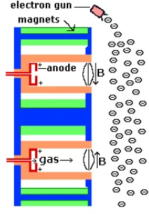
interplay of this magnetic field and the electric field between the anode propellant injectors and the electron cloud created outside of the thruster causes a current (called the Hall current) to be induced to flow azimuthally around the open annulus in the thruster. The magnetic field pushes on the current and accelerates it, and the gas it's traveling through, out of the thruster to create thrust. Note the electron gun mounted on top of the thruster. Typical thrusters in US laboratories are a foot or so across, use 1 to 5 kilowatts of power, operate at 2,200 sec specific impulse, produce less than one pound of thrust, and are 50 to 60 percent efficient. They are noted for their durability. New designs using vaporized bismuth can have efficiencies as high as 70 percent making them the efficiency rulers in the electric propulsion world. Hall thrusters come in two main variants: the Stationary Plasma Thruster (SPT) and the Thruster with Anode Layer (TAL). The SPT has insulating walls on the acceleration chamber and is longer, the TAL has conducting material lining the walls and is shorter.
FIGURE 2.3 HALL THRUSTER
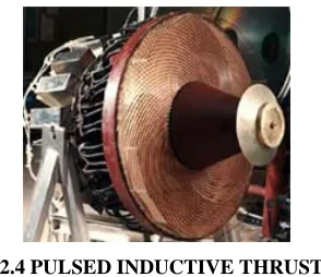
PULSED INDUCTIVE THRUSTERS
Imagine an electromagnet sitting on its end on a table. Now place a metal ring on top of it. Pulse current through the coil and a second current will be induced to flow through the ring. This induced current will flow around the ring in the direction opposite to the coil. We now have another case of a current (flowing in the ring) moving perpendicular to a magnetic field (created by the coil and directed along the coil's axis) so the Lorentz law tells us there will be a force on the ring wanting to push it away. If enough current is forced through the coil the ring will shoot straight up into the air. If the current in the coil is high enough and increases fast enough, the ring will be vaporized and ionized. Even in the gaseous state it'll still conduct the current and be accelerated away from the coil. That's what a pulsed inductive thruster is.
ISSN 2348 – 7968
FIG 2.4 PULSED INDUCTIVE THRUSTER
Pulsed inductive thrusters, are big, beautiful, sexy looking thrusters up to a meter in diameter. They operate in a pulsed mode at up to 1,000 pulses per second with specific impulses between 2,000 and 5,000 sec and thrusts of fractions of a pound to tens of pounds. Efficiencies can be as high as 50 percent.
Although the inductive coupling between the engine and plasma should imply that there is no erosion as there is in the MPD thruster, at high pulse rates the large surface area of the engine will be exposed to the thermal loading of having a virtually constant plasma mere centimeters from it. The coils could heat to the point where increased electrical resistance could cause problems or even melting. These engines are also power gluttons, eating up tens of kilowatts to megawatts of electricity.
III.DEVELOPMENTOFMETHYLPROPANEROCKETTHRUSTER
3.1CONCEPT BEHIND PROJECT
The Magneto plasma dynamic (MPD) thruster (MPDT) is a form of electrically powered spacecraft propulsion which uses the Lorentz Force (a force resulting from the interaction between a magnetic field and an electric current) to generate thrust. It is sometimes referred to as Lorentz Force Accelerator (LFA)
FIGURE 3.1 MPDT 3.2 OPERATING PRINCIPLE
ISSN 2348 – 7968
particles are propelled by Lorentz force resulting from the interaction between current flowing through the plasma and extremely applied magnetic field.
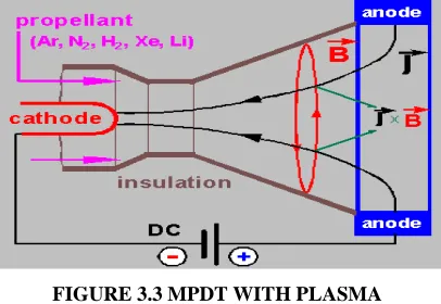
By principle there are two main types of MPD thrusters: Applied field and Self field thrusters. Applied field thrusters have magnetic rings surrounding the exhaust chamber to produce magnetic fields. In Self field thrusters there’s a cathode through the middle of the chamber. Xenon, Neon, Argon, Hydrazine and Lithium are used as propellants, but lithium proven to be the best.
Basically MPD consists of two metal electrodes. Rod shaped cathode at the centre and a cylindrical anode structure that surrounds the cathode. When a high electric arc is applied between the anode and the cathode, the cathode heats up and emits electrons. And the emitting electrons collide and ionize the propellant gas to create plasma. The electric current running through the cathode creates a magnetic field; this self induced magnetic field interacts with electric current flowing from the anode, through plasma to cathode producing a Lorentz force. This force pushes the plasma out of the structure. To produce more thrust external magnetic rings are used that creates magnetic fields to accelerate the plasma discharge.
Spacecraft propulsion is any method used to accelerate spacecraft and artificial satellites. There are many
different methods. Each method has drawbacks and advantages, and spacecraft propulsion is an active area of research. However, most spacecraft today are propelled by forcing a gas from the back/rear of the vehicle at very high speed through a supersonic de Laval nozzle. This sort of engine is called a rocket engine
FIGURE 3.3 MPDT WITH PLASMA
Irrespective of their interior details, magnetic tensor analysis yields a generic thrust relation: T = (J^2. µ /4pi) [ln (Ra/Rc) + A]
T= total thrust,
µ= vacuum magnetic permeability, J= total arc current,
Ra, Rb = effective arc attachment radii,
ISSN 2348 – 7968
IV.MODELROCKETTHRUSTER
4.1 MODEL ROCKET THRUSTER
The Model rocket thruster works on the basis of Electric Propulsion Components:
Burner
Propellant
Spark Plug
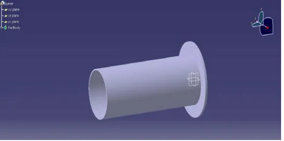
4.2 BURNER
It is a circular component in the Thruster with one end free and the other end closed. The closed end has the openings for propellant supply. Inside the burner the propellant is burnt using the spark from the spark plug, which is placed at the center of the closed end.
FIGURE 4.1BURNER DESIGN IN CATIA V5
4.3.PROPELLANT
ISSN 2348 – 7968
FIGURE 4.2TANK WITH METHYLPROPANE GAS
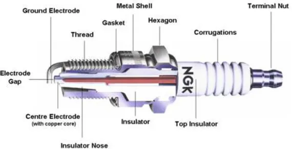
4.4.SPARK PLUG
A spark plug is a device for delivering electric current from an ignition system to the combustion chamber of a spark-ignition engine to ignite the compressed fuel/air mixture by an electric spark, while containing combustion pressure within the engine. A spark plug has a metal threaded shell, electrically isolated from a central electrode by a porcelain insulator. The central electrode, which may contain a resistor, is connected by a heavily insulated wire to the output terminal of an ignition coil or magneto.
The spark plug's metal shell is screwed into the engine's cylinder head and thus electrically grounded. The central electrode protrudes through the porcelain insulator into the combustion chamber, forming one or more spark gaps between the inner end of the central electrode and usually one or more protuberances or structures attached to the inner end of the threaded shell and designated the "side", "earth", or "ground" electrode(s).
FIGURE 4.3.SPARK PLUG
4.4.1 DIMENSIONS OF DESIGN
Burner - 200 (Length) mm
60(Outer Diameter) mm
56(Inner Diameter) mm
ISSN 2348 – 7968
Propellant Inlet - 10(Diameter) mm
4.5 3D VIEW OF THRUSTER
FIGUER 4.4 CATIA VIEW
The above figure shows the 2-D model of wing ribs plotted as per the given coordinates of base line configuration of NACA 0012. The process of wing ribs fabrication is began with determining the suitable number of rib sections and the location of main spars and sub-spars. The circular curves were then created by having a center at the center of the spar location and had a radius of 0.1 inch less than the distance between the center of the spar and the point on the contour of the airfoil perpendicular to the camber line. Each section of the ribs was cut with the CNC machine. Two generations of the rib sections were fabricated, the first generation had six rib sections and the second generation had four rib sections
The first generation provided smoother change in camber than the second generation. However, the trailing edge section of the first generation was extremely small which did not provide enough space for the actuator thus generation was selected for the wind tunnel model. With four rib sections, the main spar location was chosen at 2-in aft of the leading edge, which is 1/6 of the chord. The sub-spars aft of the main spar were 2 inches apart where the one in front of the main spar was located 1-1/4 inch from the main spar. Figure shows the drawing of wing rib cross-section.
4.6. WORKING
ISSN 2348 – 7968
The Burner is a circular device connected at one end with insulator and free in another end. The insulator which consist of four opening for the supply of propellant(Methylpropane Gas). It also provided with the Spark Plug at the center which is connected with electric supply. Whenever the Electric supply is given to the spark plug , which ignites and mixes with the propellant flow through the openings. Mixing of both Propellant and the spark results in the combustion. The burning of propellant takes place and the Flames will be developed at the rear end of the burner.
V. RESULT
5.1. CALCULATION
1. Combustion intensity
2. Specific impulse
3. Heat released
4. (Cj) jet velocity
5. Calorific value
6. Mass flow rate
Combustion intensity
CI = Heat released / Combustion volume * Calorific value
Combustion volume = Length *Area of inner Diameter
= 200*76*76
= 0.02*0.076*0.076
=1.155*10^-4
Calorific Value =49510 KJ/KG
=49.51 J/KG
Mass flow rate =p*velocity*area
=1.29*0.248*7.85*10^-5 =2.51*10^-5
Combustion intensity =49.22/49.51*1.155*10^-4 =8607.29KJ/G
ISSN 2348 – 7968
= 0.131
Spc = 1/Isp
= 1/0.131
= 7.633
5.2. PROPULSION EFFICIENCY
It determines how much of the kinetic energy of the exhaust jet is useful for propelling a
vehicle.
MASS OF METHYLPROPANE GAS
87.63 g (initial mass methylpropane cylinder)
− 86.98 g (final mass methylpropane cylinder)
0.65 g (mass methylpropane gas)
Molar mass of methyl propane (using the ideal gas law and the definition of molar mass):
PV = nRT
nmethylpropane = P methylpropaneV/RT = (0.9788302632 atm) (0.2761 L) / (0.08206 L·atm/K·mol) (294.75 K)
= 0.0111734803 molmethylpropane Molar Mass = g/mol
= 0.65 g methylpropane/0. 0111734803 molmethylpropane = 58.17345905 g/mol
EXHAUST VELOCITY
The velocity, relative to a rocket, at which exhaust gases leave the nozzle of the rocket's engine.
Delta V= V e In (MO / M)
V e = 4.494 By Newton’s second Law, F = m A
F = Force m = Mass A = Acceleration
Thrust (F) = Exhaust Velocity x rate of flow of mass = 4.4 km/s x 0.65 g
ISSN 2348 – 7968
FIGUER 5.1JET FROMMETHYL PROPANETHRUSTER
5.3. Conclusion
The methyl propane gas in our thruster created a huge thrust production and also it can be enrolled in the space rocket. By using methyl gas as propellant, the gas used in the thruster system will help the rocket to achieve the Target in a required interval of time and the thrust produced by the help of this gas will have good propulsive efficiency.
REFERENCES
[1]. en.wikipedia.org/wiki/Rocketengine
[2]. en.wikipedia.org/wiki/Cryogenic_rocket_engine [3]. www.grc.nasa.gov/WWW/k-12/rocket/rktengperf.html [4].grabcad.com/library/g80-13t-model-rocket-engine [5.grabcad.com/library/tag/rocke
[6] . www.ijstr.org/final.../Modeling-And-Analysis-Of-Rocket-Outer-Shell.pdf [7].en.wikipedia.org/wiki/Isobutane