Applications of Smalltalk/V to
Digital Image Processing
A thesis submitted in fulfilment of the requirements for the award of the degree of
MASTER OF SCIENCE
from
Victoria University of Technology
by
Fei Liu, BE
Department of Computer and Mathematical Sciences
Abstract
The author has demonstrated Smalltalk as a medium for explorations in image processing by creating within it an expandable environment for image processing. He has produced two versions: one for DOS, and one for Windows which is hereafter referred to as ImageLab. The Windows version, ImageLab, may be used in two ways: as a stand alone by a non-programmer for whom the existing functionality is adequate; or within the Smalltalk environment by a programmer who might wish to expand the functionality.
In creating ImageLab the author recognised that:
• the BitBlt operation was eminently suitable for implementing basic morphological operations;
• and that Smalltalk was eminently suitable for implementing other morphological operations as algebraic expressions in three basic operations (using Huang's BIA). He has given examples to show ImageLab 'in action'. In particular, he has applied his environment to making a contribution to the detection and counting of clusters of points (relevant to the detection and counting of clusters of microcalcifications revealed in mammograms of patients with early signs of breast cancer).
1
•nppljii^iif inn
JL^Cl^Iill < H I w l I
The candidate hereby declare that the work in this thesis, presented for the award of the Master of Applied Science and submitted in the Department of Computer and Mathematical Sciences, Victoria University of Technology
:-• is that of the candidate alone and has not been submitted previously, in whole or in part, in respect of any other academic award and has not been published in any form by other person except where due reference is given, and
• has been carried out during the period from January 1992 to February 1994 under the supervision of Dr. Don Watson and Mr. Tom Peachey.
Signature
=— •- — - •
Acknowledgments
The author of this thesis wishes to acknowledge the following organisations or people for directly or indirectly providing assistance and guidance while carrying out this research and writing this thesis.
Dr. Don Watson and Mr. Tom Peachey, the academic supervisors, for their patient,
encouraging supervision, invaluable guidance and assistance, enlightening advice and suggestions, and constructive criticisms during the research and preparation of the thesis.
Mr. Robert Hinterting, for Smalltalk and debugging of my programming. Thanks are
extended to Associate-Professor Charles Osborne, Mr. Alasdair McAndrew, Mr.
Martin Schweitzer, Dr. Hao Shi for their constructive suggestions, and the people
who discussed the topic with me through internet.
Mr. P. Rajendran and Mr. Damon Burgess, technical officers, for their significant help in providing machines, manuals and other facilities.
The Australian International Development Assistance Bureau, for providing the scholarship covering tuition fees and health insurance cover.
Since the English is the author's second language, a lot of people helped him when he wrote the thesis. The author would like to give his thanks to Dr. Don Watson, Mr.
Tom Peachey, Mrs. Betty Watson and Mr. Mehmet Tat.
Table of contents
Abstract
Declaration
Acknowledgments
Table of contents
List of figures
List of tables
1
a
iii
iv
viii
xi
Chapter One
1.1
1.2
Chapter Two
2.1
2.2
Introduction 1
The problem 1
The scope of the thesis 2
Image-processing languages - a brief review 5
The computer and digital image processing 5
The computer languages used in image
processing 7
Chapter Three
3.1
3.2
3.3
3.3.1 3.3.2 3.3.3 3.3.43.4
3.4.1 3.4.2
Object-oriented techniques and Smalltalk 9
The history of object-oriented technology 10
The history of object-oriented programming
languages 10
Constituents of an OOL 11
Programming with objects 11 Computation by message-passing 11
Abstraction to classes and subclasses 12 Programming in the presence of inheritance 12
The benefits of introducing OOL to image
processing 13
Modelling an image as an object 14
3.4.3
3.5
3.6
3.7
3.7.1 3.7.2 3.7.33.8
3.8.1 3.8.2Chapter Four
4.1
4.1.1 4.1.24.2
4.3
4.3.1 4.3.2 4.3.34.4
4.4.1 4.4.2 4.4.3 4.4.4Chapter Five
5.1
5.2
5.2.1 5.2.2 5.2.3 5.2.4 5.2.55.3
5.3.1 5.3.2Quadtree and multi-resolution
The history of Smalltalk
Smalltalk versus other OOLs
The development environment
Inspecting an instance of Form
Browsing a disk file containing a Form Constructing windows
Bit-block transfer (BitBlt)
The operationsAdvantages of Smalltalk in image processing
Mathematical morphology and image algebra
The overview of morphology
Image and image transformation
Mathematical morphology for binary images
History of image algebra
Huang's image algebra
Two principles and the basic elements Three basic operations
Other operations
Applications of image algebra in Smalltalk
Applications: filtersApplication: shape recognition (template matching) Application: edge detection
Application: convex hull
Development of image-algebra applications in
Smalltalk
Overview of image-processing applications
An image-processing system in Smalltalk/V286
The user interface of the application The class ImageDataBaselnspector The class ImageProcessor
Adding methods to a system class Limitations in SmalltalkA^286
ImageLab in Smalltalk/VWin
The SmalltalkAWin environment The classes GraphLab and ImageLab
5.3.3 5.3.4 5.3.5
5.4
Chapter
6.1
6.2
6.3
Chapter
7.1
7.1.1 7.1.2 7.1.3Chapter
8.1
8.1.1 8.1.28.2
Chapter
9.1
9.2
9.2.1 9.2.3 9.2.3 9.2.4Six
Seven
Eight
Nine
References
Appendices
Appendix A
Multi-Document Interface Tool bar and status bar On-line help systemCustomised design
Exploring gray-scale images
Ways of viewing gray-scale erosion and
dilation
Pseudo gray-scale morphological operations
Three-level gray-scale images
An application of ImageLab
Labelling connected components in binary
image
The classical method The morphological method
Application of the new labelling method
Non-morphological image processing methods
in Smalltalk
Quad-tree in Smalltalk
Quad-tree fundamentals Quadcode in Smalltalk
Adaptive quadtree: A new method for image
coding
Conclusion and further work
Conclusions
Further work
Further work on gray-scale images Other Smalltalk platforms
Object-oriented image database An image processing language
Disk 1 (The programs in VWin)
Appendix B Disk 2 (Sample images and programs in V286) Al
Appendix C Classes and methods of Small-Image Database A2
Appendix D Classes and methods of Image processor A6
Appendix E Classes and methods of Image(V286) A14
Appendix F Classes and methods of ImageLab A19
F.l Methods in class Bitmap A19
F.2 Methods in class ImageLab A31
F.3 Methods in class ILTextWindow A49
F.4 Methods in class Image Window A50
List of figures
Figure 2.1 Fundamental steps in digital image processing 6 Figure 3.1 Illustration of the relationship between class and objects 12
Figure 3.2 An image object 15 Figure 3.3 Class Image and its hierarchy 16
Figure 3.4 Partitioned image 17 Figure 3.5 Corresponding quadtree of partitioned image 18
Figure 3.6 A typical Smalltalk environment(VWin) 21
Figure 3.7 An instance of class Form 22 Figure 3.8 Bit array of form circular disk 22 Figure 3.9 The form store format in Smalltalk/V286 23
Figure 4.1 Illustration of dilation 28 Figure 4.2 The three basic operations 33 Figure 4.3 Sample images for the difference operation 35
Figure 4.4 Sample images for the intersection operation 35 Figure 4.5 Sample images for the erosion operation 36 Figure 4.6 Sample images for the symmetric difference operation 37
Figure 4.7 Sample images for the open operation 38 Figure 4.8 Sample images for the close operation 38 Figure 4.9 Sample images for the hit or miss transform operation 39
Figure 4.13 Sample images for removing high frequencies 42
Figure 4.14 Sample images for band pass filter 43
Figure 4.15 Sample images for shape recognition 44
Figure 4.16 Sample image of edge detection 44
Figure 4.17 Sample image of convex hull 46
Figure 4.18 Sample images of shape analysis by using convex hull 46
Figure 5.1 The run-time structure 50
Figiu*e 5.2 The user interface of the Small-Image Database 51
Figure 5.3 The window of image processor environment 52
Figure 5.4 The structure of class ImageDatabaselnspector 55
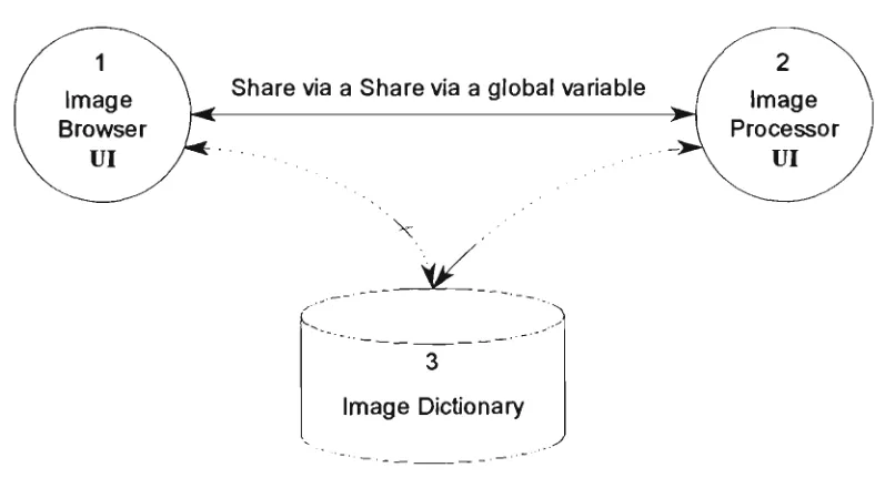
Figure 5.5 Communication via a global variable Q 57
Figure 5.6 Class hierarchy structure 61
Figure 5.7 A typical ImageLab working environment 68
Figure 5.8 Tool pane of ImageLab 69
Figure 5.9 Status pane of ImageLab 69
Figure 5.10 Work flow diagram 71
Figure 5.11 Contents of ImageLab's on-line help system 72
Figure 6.1 OR table 81
Figure 6.2 MAX table 81
Figure 6.3 The original image (Lena) 82
Figure 6.4 The edge detected image 83
Figure 7.1 J shapes template for blob colouring 87
Figure 7.2 L shapes template for blob colouring 89
Figure 7.3 Original image for D-transform 91
Figure 7.4 D-transformed image 91
Figiu^e 7.5 Foreground reference image 92
Figure 7.6 Background reference image 92
Figure 7.7 Original image 92
Figure 7.9 The original image X 93
Figure 7.10 The noise need to be removed 93
Figure 7.11 High frequency noise is removed 93
Figure 7.12 The blobs of interest are extracted 93
Figure 7.13 Selected blobs transformed to single points 93
Figure 7.14 The band filter image pair 94
Figure 7.15 Original image with clusters 95
Figure 7.16 Structuring element 95
Figure 7.17 Result after closing operation 95
Figure 7.18 Selected blobs transformed to single points 95
Figure 8.1 Representation of a binary image by a region quadtree 97
Figure 8.2 The original image 101
Figure 8.3 The quadtree 101
iilil?
A t* 'j_ l 1 '
|||)f tables
Table 3.1 An image class
Table 3.2 A subclass of image class
Table 3.3 The form store format in Smalltalk/VWin
Table 3.4 BitmapFilelnfoHeader format
Table 3.5 Bit Block operations
Table 4.1 Five basic elements
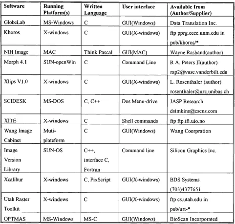
Table 5.1 A survey of current image-processing software
16
16
23
23
25
32
Chapter 1
Introduction
1.1 The problem
One of the approaches traditionally used for the building of image-processing systems makes use of subroutine libraries. Such an approach, while allowing some ease of development through standard pieces of software in the context of widely diffused languages, such as Fortran or C[CART89], has significant limitations. Extensibility is restricted: the collage of routines with other pieces of software can produce inconsistencies due to the overlaying of global control variables and the possible mismatch of the routine interfaces with the problem to be solved. Speed is affected by the difficulties of supporting integration for specific architectures.
Recent developments in the field of programming languages, specifically object-oriented programming, offer a highly modular structure of programs, good reusability of software modules with ease of reconfiguration and a single data model between the main memory and the database. Moreover, object-oriented languages allow the extension of the basic data types to data types related to the specific application. For example in the development of an image-processing system, an object-oriented language will facilitate the creation of an image data-type. In this way, a highly specific development environment can be created, based on standard platforms, without the need to define specific languages.
This work develops an image processing system within the Smalltalk environment. Since our aim is to explore the use of object-oriented programming in image processing, the system does not offer all the facilities of a commercial imaging system. In the main we have concentrated on those techniques based on mathematical
morphology.
Mathematical morphology modifies an image by applying various binary operations to the image and a smaller image, called the structuring element. The first systematic treatment of mathematical morphology was the two-volume work by J. Serra
[SERR82a]. However, a visit to Serra's work could well be prefaced by the reading of two relevant chapters of a recent book by R.M. Haralick and L. Shapiro [HARA92]. In the course of developing his Digital Optical Cellular Image Processor (DOCIP), K-S Huang [HUAN89] devised a Binary-Image Algebra (BIA) which allowed him to express morphological operations in terms of three fundamental operations. These three operations are implemented in Smalltalk as basic methods in this work.
Within Smalltalk the key underlying process in the author's work has been the
bit-block transfer (BitBlt). BitBlt appears to the programmer as a parallel operation on a
rectangular array of bits(or bytes) and the operations of BitBlt are admirably suitable for morphological operations.
The use that one can make of image-processing software is limited by the flinctionality provided by the designer. There is a place for software that is expandable in the hands of a user. The present work creates within the Smalltalk environment a sub-environment for image processing. The environment may be used as a stand alone program, in which case no knowledge of Smalltalk is required. Alternatively, it may be run from inside the Smalltalk environment using only a cursory knowledge of Smalltalk. Within that environment the kernel operations may be readily expanded by a Smallalk programmer to perform other processes required by the user.
1.2 The scope of the thesis
In Chapter Three, we introduce the object-oriented concepts, and the benefits which an object-oriented language can offer to image processing. Also in this chapter, we demonstrate how to model an image as an object. Beginning with a brief history of Smalltalk followed by a comparison of Smalltalk with other object-oriented languages, we highlight two features of Smalltalk particularly pertinent to image processing - the graphics classes and the bit-block- transfer operation.
Chapter Four presents the theoretical background of this project. We begin with a brief introduction to the concept of mathematical morphology and its history. We then turn to Huang's image algebra [HUAN89] which expresses each morphological operation in terms of three fundamental operations. For each operation we state Huang's expression, give the Smalltalk method implementing it, and use Smalltalk to generate the images illustrating the operation.
The core of Chapter Five is a description of the image-processing environment which we have developed in Smalltalk. This chapter begins with a brief overview of existing image-processing packages available either commercially or from the public domain, and running under the most common operating systems (DOS, Windows, Macintosh and UNIX). We then introduce our own image-processing environment in two versions: (1) the DOS version and (2) the Windows version - ImageLab.
Chapter Six gives an exploration on gray-scale images. First we introduce a different ways of viewing the gray-scale dilation, then we present the pseudo gray-scale morphological operation.
The purpose of Chapter Seven is to show ImageLab in action by describing how the author used ImageLab to make a contribution to the research on the counting of 'blobs' in a binary image. Chapter Eight complements the preceding chapter by giving two examples of the implementation of non-morphological operations. In the first we create a class QuadCode which offers an introduction to multi-resolution techniques, and propose the adaptive quad-tree. In the second we explore the fast Fourier transform (FFT).
The final Chapter of the thesis contains the concluding remarks and some suggestions for fiiture work.
words (instance variable, method names, class names, etc) are embedded in ordinary text.
Chapter 2
Image-processing languages - a brief review
Introduction
This chapter gives an overview of digital image-processing. We begin with a brief history of the impact of computers on image processing, and display the structure of a modem digital image-processing system. We then survey the computer languages, including object-oriented languages, that are used in digital image-processing.
2.1 The computer and digital image processing
Digital image-processing is used for two different purposes:
• enhancing particular aspects of an image; and
• preparing images for the measurement of the features and structures present.
At that time ( from late 60's to early 80's), there were three prominent scientific applications of digital image processing: (1) remote sensing, (2) medical imaging and (3) particle physics. Images in such applications are large, require high resolution, and need much computation time. The cost was such that only government and military agencies, in the main, could sponsor the work.
Today, we are in the middle of a revolution sparked by the rapid progress in video and computer technology. Personal computers and workstations have become powerfiil enough to process image data. They have also become cheap enough to be widely used. Consequently, image processing is turning from a specialized science in areas such as astronomy, remote sensing, electrical engineering, and computer science into a standard scientific tool. Applications of image processing are now found in virtually all natural sciences[JAIN89] and are serving many industrial purposes (eg. robot vision).
A general digital image processing system involves five sub-systems which are
[GONZ92]:-1. image acquisition, 2. image storage, 3. image processing,
4. image communication, and 5. image output.
The fundamental steps in digital image processing are shown in the following
diagram:-Segmentation Representation & description / " T
Pre-Processing
7r\—
^
Image acquisition
\l/
(r
Knowledge base
Problem domain
Recognition and
interpretation
Output lUt
Storage
Digital images can be acquired by video cameras, scanners and other digitisers. Output devices include monitors, film and printers. Storage of images entails the need for high capacity devices such as optical disks, magnetic tapes and magnetic hard disks. Software for genemal-purpose digital image-processing tends to be concentrated in the areas of pre-processing, segmentation, representation and description, recognition and interpretation [RUSS92].
2.2 The computer languages used in image processing
The origins of image-processing languages in the United States lie in two projects: (1) the DoD (ARPA)-sponsored ILLIAC project at the University of Illinois[McC063] from which evolved the PAX language, later more fiilly developed and documented at the University of Maryland and (2) the NASA-sponsored IPL (Image Processing Laboratory) at JPL (Jet Propulsion Laboratory) which produced the language VICAR (Video Image Communication and Retrieval) reviewed by Castleman[CAST79]. These projects were implemented in the early to mid-1960s. PAX was written as a collection of FORTRAN subroutines to run on the Univac 1108, while VICAR, also in FORTRAN, was written for the IBM 360. PAX is a general purpose image-processing language while VICAR is more mission oriented being intended for use with the Ranger, Surveyor, Mariner, Viking and Voyager space exploration projects[PRES81].
It is not surprising that, until the early 1980s, FORTRAN was the language most widely used for digital image processing[PRES83]; it was widely available on many platforms and could satisfy the heavy computational demands of image processing.
However, since even the best FORTRAN compilers can not always generate assembly language optimised for rapid manipulation of arrays of numbers, many image-analysis systems are partly coded directly in assembly language, thus placing a burden on the image-processing programmer especially one whose training is not in computer science.
Today, many widely used image-processing packages are written in CpLIND91]. Khoros, a complete image-processing package, running on the Sun-Sparc workstation, which has been placed in the public domain, is completely written in C. This package is widely used by scientists around the world, and there is a very active news group on Internet. Much commercial image-processing software is also written in C; examples are GlobLab Image from Data Translation, and OPTIMAS from BioScan Incorporated.
Other popular computer languages are also employed in image processing. Pascal, a typical procedural computer language, was used to create NIH Image 1.52, image processing software for the Macintosh. Prolog was used by Vision Dynamics in creating the VSP software[BATC91].
Image-processing languages have also emerged as extensions of existing computer languages. An example is PICL (Pictorial C Language) which is an extension of PCL (Pyramid C language) and is oriented to image analysis because it supports pictorial data-types[GESU91].
Chapter 3
Object-oriented techniques and Smalltalk
Introduction
This chapter has two objectives: to introduce object-oriented technology and its relevance to image processing; and to show why we have chosen Smalltalk as our medium for applying object-oriented techniques to image processing.
To attain the first objective we begin with a brief review of the history of oriented technology, and oriented languages (OOLs). We then examine object-oriented languages in more detail. We shall discuss the main constituents of an OOL. These will include objects, messages, methods, classes and inheritance. We shall then be ready to see the benefits which an OOL can offer to image processing. We shall see how an image may be treated as an object, how objects with identical behaviour and structure may be gathered in to a class, and how inheritance enables the commonality of similar classes to be elevated to a superclass. As a further example, we shall see how readily a data-structure such as a quad-code, which is part of the image-processing toolbox, may be accommodated within the Smalltalk system.
The work of this thesis conjoins two activities - image processing and object-oriented programming. Of the various object-oriented languages the one that emerged as most suitable for our task was Smalltalk, the subject of the second objective of this chapter. After a brief note on the history of Smalltalk and comparison with other OOLs we turn to a description of the Smalltalk environment.
Smalltalk is the purest, and amongst programming environments, Smalltalk's is the most creative and productive.
Finally we highlight two features of Smalltalk particularly pertinent to image processing - the graphics classes and the bit-block transfer operation.
3.1 The history of object-oriented technology
The first person to formally identify the importance of composing a system in levels of abstraction was Dijkstra [DIJK76]. Pamas later introduced the concept of information hiding [PARN72] which is central to the nature of an object. The greatest influence upon object-oriented development derives from a small number of programming languages which will be discussed in the next section. In two decades, the object-oriented technology has become mature and has divided into several branches such as, object-oriented language (OOL), object-oriented programming (OOP), object-oriented analysis (OOA) and object-oriented design (OOD)
3.2 The history of object-oriented programming
languages
Several programming languages have contributed to the evolution of today's object-oriented programming languages (OOL). In the 1950s, LISP, a language for list processing, introduced the concept of dynamic binding. SIMULA 67, developed in the 1960s as a language for programming simulations, introduced the class as a language mechanism for encapsulating data, and inheritance as a mechanism for elevating the commonality of two classes into a superclass. Data abstraction, in the form of abstract data types, was introduced in the r970s, first in academic languages such as CLU, developed at the Massachusetts Institute of Technology, and later in more commercially popular languages such as Ada and Modula-2. With the beginning of the 1980s came the real dawn of the object-oriented programming era. Smalltalk-80 was introduced commercially in 1983. Other object-oriented programming languages, such as C++, Objective-C, Eiffel, the Commom Lisp Object System, and Actor became commercially available [C0X91].
everything is an object. This group includes Smalltalk, Actor, and Eiffel. The other camp includes the hybrid languages such as C++, Objective-C, The Common Lisp Object System (CLOS) and the various object-oriented Pascals [WINB90].
In general the pure object-oriented languages emphasise exploration and rapid prototyping, while hybrid languages emphasise runtime speed and ease of incorporating object-oriented extensions for the programmer with an orientation towards procedural languages. The more mature OOLs, such as Smalltalk, also offer robust class libraries and rich sets of development tools. These capabilities are gradually being incorporated into the hybrid languages.
3.3 Constituents of an OOL
An object-oriented programming language has four basic mechanisms. They
are:-• Objects,
• Messages and methods, • Classes, subclasses, • Inheritance.
3.3.1 Programming with objects
A traditional program consists of procedures and data. An object-oriented program consists only of objects that encapsulate both procedures and data. An object orientation views such a system as a collection of objects, where each object models an entity or event in an application problem and where all objects work together to achieve the goal and task of the overall system. The central software concept is "object". An object captures the identity, structure and behaviour of the application entity that it represents.
3.3.2 Computation by message-passing
Methods are procedures which reside in an object and determine how the object acts when it receives a message. The instance variables store information or data local to the object. Methods execute in response to messages and manipulate the values of instance variables. Methods may also send messages to other objects requesting action or information.
3.3.3 Abstraction to classes and subclasses
A class is a description of a set of nearly identical objects. It consists of methods and data that summarise common characteristics of a set of objects. The ability to abstract common methods and data descriptions from a set of objects and store them in a class is central to the power of object-orientation. An object is an instance of a class. A class can also summarise common elements for a set of subclasses. By using subclasses, object-oriented programmers describe applications as collections of general, or abstract, modules. Common methods and data are elevated as high as possible so that they are accessible to all relevant subclasses. The relationship between a class and its instances is similar to the relationship between a factory and its
products:-CD
Products - Objects
Factory - Class
Fig. 3.1 niustration of the relationship between class and objects
3.3.4 Programming in the presence of inheritance
the object-oriented concept that contributes most to the increase in productivity which flows from the use of an object-oriented programming language.
Classes and their subclasses form class hierarchies, which capture the "is a" relationship among them. An instance of a derived class is also an instance of all its superclasses. While object-oriented languages all implement inheritance, they vary in how they treat multiple inheritance, and how they handle the access and redefinition of features in a subclass that are defined by a superclass. For example, some languages provide multiple inheritance, which means that classes can have more than one
superclass. These languages provide more generality, solving, for example, problems like expressing what a toy house is. Is it a kind of toy, or is it a kind of house? With mutiple inheritance, it can be both [C0X91].
3.4 The benefits of introducing OOL to Image
processing
Four key concepts that summarise the advantages of the object-oriented approach are
encapsulation, abstraction, polymorphism and persistence [MEYE88].
Encapsulation is the formal term used to describe the bundling of data and methods
inside an object. It provides information hiding* as well as access to selected features of an object.
Abstraction is defined as extracting essential properties of a concept. It allows us to
neglect the specific details of something and focus on its essence.
Polymorphism is the capability of program entities to belong to more than one type.
The same message may be defined in several classes and an argument passed by a message is not restricted in type. It allows the specification of algorithms at higher or more abstract levels.
Persistence refers to the permanence of an object, that is, the amount of time for
which it is allocated space and remains accessible in the computer memory.
Before talking about the utility of image processing in an OOL, we need to examine the general benefits of an OOP language. An object-oriented programming language offers a major opportunity for improving software productivity [EGE92]. A programming language that supports the object-oriented paradigm benefits the software developer by providing a natural way to model complex, real-world phenomena, this resulting in faster and easer coding. The overall approach of reducing code by using inheritance to program the differences is one of the key tactics of object-oriented programming and a unique capability of object-oriented languages. Pre-defined class libraries, a component of the mature object-oriented languages which results in a reduction of design time and coding time, enhance the benefits of using object-oriented languages.
Encapsulation is one of the most beneficial concepts in the context of object-oriented programming. It combines data structures and functionality into objects. It also hides internal aspects of objects from its users and declares which features of an object are accessible[Y0UR91a].
Another very important characteristic and benefit of object-oriented programming is that the interpretation of a message is in the hands of the receivers. Operations exhibiting this property are said to be polymorphic. Messages can be thought of as late-bound procedure calls, where the actual method of procedure to be invoked is not determined until the message is actually sent to a specific receiver. The programmer does not have to memorise a unique vocabulary for each class used in building his applications[YOUR91b].
3.4.1 Modelling an image as an object
Like other objects in the real world, images can be modelled as objects. Images have common characteristics which can be used in the description of the image. For
example:-Size ~ width and height. Colour — mono or colour. Resolution ~ bits per pixel.
Operations frequently performed on images are:
Copy ~ copy to another device. Cut ~ cut partial image.
Paste ~ paste another image to the image. Reflect ~ reflect the original image about a line.
Complement ~ forming the photographic negative of the image.
In OOP this set of operations is called the behaviour of the image objects. Other examples of operations, combine two images, are the union of image and logical operations such as the logical a/iJ of pixel values.
The data and the behaviour can be encapsulated into an object. A set of image objects may be represented as a pack of
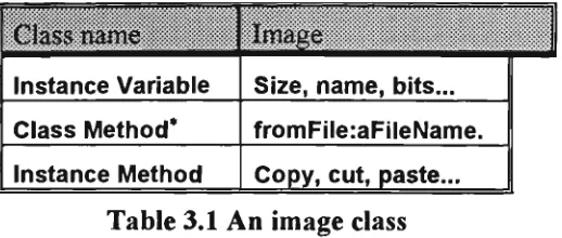
templates:-3.4.2 Image class
Image:-Class name
Instance Variable
Class Method* Instance Method
Image
Size, name, bits...
fromFile:aFileName.
Copy, cut, paste...
Table 3.1 An image class
We can then introduce subclasses of Image to differentiate among binary, grey-scale and colour images. Consider, for example, a class Binarylmage as subclass of the class Image. Taking advantage of inheritance, we do not need to re-code the copy, cut and paste methods. The instance variables and methods of the class Image will be inherited by the class Binarylmage, and methods may be re-defined if necessary. Additional instance variables and methods which might be needed by the class Binarylmage may be added to it. In the following table, the parentheses enclose what is inherited from the
superclass:-Sub-Class nam€
Instance Variable
Class Method
Instance Method
Binarylmage
(Size, name, bits...) offset (fromFile:aFileName...), fromScreen...
(Copy, cut, paste...), union, reflect...
Table 3.2 A subclass of image class
In the same way we may define classes GrayScalelmage and Colorlmage as subclasses of the class Image, thus yielding the following class hierarchy
:-GrayScalelmage Colorlmage
Fig. 3.3 Class Image and its hierarchy
An object-oriented programming language supports polymorphism which allows us to pass the same message to objects produced by different classes. When an object receives a message the method for the message will be found in the class to which the receiver belongs. For example, the unary message selector union might be found in the class GrayScalelmage and in the class Binarylmage, but the methods would be different. When the message union is passed to an object which is an instance of class Binarylmage, the method union in class Binarylmage will be executed.
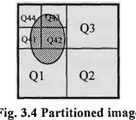
3.4,3 Quadtree and multi-resolution
A quadtree is a tree data-structure (a tree in which each node has exactly four descendants) which represents an image [HARA93]. Each node of the quadtree represents a square subset of the image's spatial domain. The root node of the quadtree represents the spatial domain of the entire image. If all pixels of the square represented by a node have the same value, then that node becomes a leaf in the tree. If the image being represented is a binary image, then the corresponding quadtree is called binary quadtree. If the image represented is a gray-scale image, then the corresponding quadtree is called a grey-scale quadtree.
For example, suppose we have the following
image:-Fig. 3.4 Partitioned image
follows:-Fig. 3.5 Corresponding quadtree of above partitioned image
The root of the tree corresponds to the entire image, and each set of four child nodes of a parent node corresponds to a subdivision of the square represented by the parent node. In this case it is only the quadrants represented by Ql and Q4 which have undergone further subdivision since all the pixels in Q2 and Q3 have the same value.
Since we model the image as an object and abstract it into a class and its subclasses, it is easy to use the data structure to encode and decode an image. All we need to do is to introduce a few instance methods into the class Binarylmage ( to encode a binary image). If the method offers scope for generalisation we can elevate it to the class Image. We need to introduce instance methods as follows
:-• Introduce in the class Image an instance method to return a nominated quadrant of an Image - quadrant: anint
• Introduce an instance method in the class Image to return a 'sub-quadrant' or quadcell by a Quadtree - quadcellAt: aQuadcode
• Introduce in the class Image an instance method to determine whether an image is white (pixel values equal to 1 if we deal with a binary image) - is White.
• Introduce an instance method in the class Image which returns an OrderedCollection of instances of Quadcode, indicating the quadrants which are white - quadsWhite
Two more instance methods are introduced into the class Image,
quadRecursiveWhite and quadRecursiveWhiterqC qCdCllln:qCdColln, which
specify all quadrants and sub-quadrants.
Chapter Eight which discusses non-morphological image-processing methods in Smalltalk.
The class Quadtree exemplifies the use of object-oriented techniques in image processing. The first benefit is that we only need to program the difference, since the class Quadtree is a subclass of OrderedCollection. This not only increases our programming productivity but also reduces the number of mistakes in coding the program thus reducing the time spent in debugging. Another obvious advantage is the reuseability of the code. Some of the methods for a binary image will be applicable to a gray-scale image or a colour image without modification because we defined GrayScalelmage and Colorlmage as subclasses of the class Image. More advantages will be discussed in later chapters.
3.5 The history of Snnalltalk
In the eariy 1970s, Alan Kay and Adele Goldberg developed the Smalltalk system at the Software Concepts Group of the Xerox Palo Alto Research Centre. While not the first object-oriented programming language, it was Smalltalk which lead the way into the object-oriented era [WINB90].
The first publicly available version of Smalltalk was released in 1983 as Smallltalk-80. It was a result of evolution from the early versions Smalltalk-72, Smalltalk-74, Smalltalk-76 and Smalltalk-78 respectively. Smalltalk-80 was initially available only on powerful graphical workstations. Because Smalltalk is embedded in a complete interactive programming environment it requires significant memory, computing, and graphics capabilities. However these requirements become less onerous as the cost of memory, storage and speed falls. The current versions of Smalltalk, Object-works for Smalltalk-80 and SmalltalkA^, are available for a range of computers, from small personal computers up to the most advanced graphical workstations [LALO90a].
There are also two versions of Smalltalk which reside in the public domain: Little Smalltalk which implements the language only and provides a text-based user interface; and GNU Smalltalk, which is based on the XI1 window system.
In this chapter, VWin refers to SmalltalkA^in and V286 refers to SmalltalkA^286. SmalltalkA^ is available on various personal platforms such as PCs and Macs.
3.6 Snnalltalk versus other OOLs
Smalltalk is the purest of the object-oriented languages. In Smalltalk every object is an instance of a class; in contrast, C++ grafts class objects onto the non-class objects of C. In Smalltalk a variable is a pointer to an object, the assigimient operator re-directs a pointer, and one explicitly makes a copy of an object when necessary; in contrast, in C++, making copies is implicit and one must explicitly introduce pointers in order to avoid copying. In Smalltalk it is implicit that all objects are created at runtime, and a garbage collector gathers any object which is no longer referenced by another object; in contrast, in C++, one must explicitly use new to create an object at runtime, and use d e l e t e to reclaim its space. In Smalltalk it is implicit that the method invoked by a message is determined by the class (rather than a superclass) of the receiver; in contrast, in C++, one must explicitly use virtual to accomplish the same effect. SmaUtalk has always been equipped with a vast library of classes; in contrast, although class libraries have begun to appear with various C++ compilers, they have yet to achieve the commonality that exists amongst the dialects of Smalltalk.
The cost of simplicity and purity can be loss of power. Smalltalk achieves encapsulation by hiding all instance-variables and exposing all instance-methods. C++ grants the programmer the discretion to classify members as private or public (or protected).
However all such comparisons as above must be relative to the context in which the language is to be used. For example, if the context is the teaching of object-oriented programming then Smalltalk has much to commend it, even though a novice, especially if the person is an experienced programmer of conventional languages, might find it hard to master the Smalltalk approach at the begiiming. The biggest step is to write the first Smalltalk program. After that, programming productivity will rapidly increase.
Smalltalk also excels in the context of exploring concepts from some domain, such as image processing.
3.7 The developnnent environment
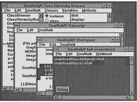
Smalltalk provides the richest and most mature programming environment. Smalltalk programming is characterised by a total integration of tools. Editors, file managers, compilers, debuggers, and print utilities are all included wdthin the Smalltalk environment. All those tools are available at all times. The Smalltalk programmer carries on a series of activities or conversations with individual tools. These activities can be interleaved. Activities or conversations can be interrupted and resumed at any time without loss of context or information. Switching from one activity or conversation to another is as simple as clicking a mouse button. The following is a typical screen display in the Smalltalk development
environment:-Fig. 3.6 An typical Smalltalk environment(VWin)
modified code can be recompiled and tested in a matter of seconds. Sequences of such modifications result in working prototypes and eventually elaborate designs that can be polished and turned into finished applications. This style of program development could be described as programming by iterative enhancement.
3.7.1 Inspecting an instance of Form
The two fundamental classes for creating and manipulating graphical images in Smalltalk-80 are the classes Form and BitBlt. Forms are used to represent images, while instances of class BitBlt represent operations on forms. The corresponding classes in VWin are Bitmap and GraphicsTool respectively.
Let us examine an instance of the class Form. The data of an instance of Form comprises a height, a width, an offset, and a bit-array that stores the image. The offset of a form is the amount by which the form should be offset when it is displayed or when its position is tested. Every form has an assumed origin at the top left-hand comer of the image. For example, we have a form of a circular disk as
follow:-Q
Fig. 3.7 An instance of class Form
This disk form has height and width equal to 32 and an olTset 0@0. The bit array
In the above figure, "1" represents a white pixel in the circle form and "0" stands for a black pixel in the form.
3.7.2 Browsing a disk file containing a Form
Different platforms have different ways of storing forms. In SmalltalkA'^ 286 we shall define our own file format
as:-iiiliigiiiiiiiiiiii ^^•ilfpiliiiiiiiiliii
space Image namc(8)
space Width(2) Height(2>
Bit
Arrav(n)
Fig. 3.9 The form store format in SmalltalkA^286*
In SmalltalkAWin, forms (images) are stored in windows bitmap format. A bitmap file stored by SmalltalkA^in will have following
structure:-Bitmap File Header
Bitmap Information Header
Bitmap Byte Array
Table 3.3 The form store format in SmalltalkA^in
The BitmapFileHeader in the above table is the first fourteen bytes of the bitmap file. The following table illustrates the BitmapFileHeader structure*:
Field Type
WORD DWORD WORD WORD DWORD
Argument Type
bfType bfSize bfReserved bfReserved bfOffBits
Description
Type of file Size of file RESERVED RESERVED
Offset to beginning of bitmap
Restrictions
Must be BM
Specified in DWORDs Must be set to 0 Must be set to 0 Specified in bytes Table 3.4 BitmapFilelnfoHeader Structure Format
* Numbers shown in parentheses are bytes occupied in the format
3.7.3 Constructing windows
We can easily manipulate images with the help of Smalltalk's graphical programming enviroimient. To construct a graphics window to display images, we need to invoke the GraphicPane class in V286 or the GraphPane class in VWin, to obtain an instance of those classes.
VWin graphics windows are built on a graphics interface language called Graphics Device Interchange (GDI) in Microsoft Windows. In run time, VWin calls the GDI library functions to implement Smalltalk graphical operations.
3 . 8 Bit-block t r a n s f e r (BitBlt)
The class BitBlt is the heart of Smalltalk's graphics system. It performs all bitmap manipulations. Smalltalk-74 was the first Smalltalk to used BitBlt as its main operation for bitmap graphics. The specification for BitBlt arose out of earlier experience with Turtle graphics, text display and other screen operations such as scrolling and menu overlays. The specification of BitBlt has been used by others under the name RasterOp. These operations are implemented directly as machine-coded primitives to improve performance [KRAS83].
Recent work by Simon Lau [LAU93] demonstrated the performance gains in using BitBlt. He produced various implementations of Conway's game of Life in V286. The best time he could get without BitBlt was 3 minutes. He then used the BitBlt algorithm from Adele Goldberg's book "Smalltalk-80 The language" [GOLD89], and reduced the time to 7 seconds - reduction by a factor of about 25.
3.8.1 The operations
3 7 1
1
4
6
• '
Form over destination becomes source
Form orRule source OR into destlnafion Form andRule source AND into destination
Form under source AND into destination
Form erase if source is 1 then destination becomes 0
Form reverse source XOR into destination
Form orThru first erase without specifying mask form, then OR with mask form specified
Table 3.5 Bit Block operations*
VWin uses Window's 256 BitBlt operations which include the seven operations in V286. In SmalltalkA^286 syntax, the copyBits message is executed like
this:-dForm copy: (sPoint extent:sExtent) from: sForm
to: dPoint rule: anInt
3.8.2 Advantages of Smalltalk in image processing
An important class of image processing algorithms is based upon the theory of mathematical morphology, described in detail in the next chapter. Morphological operations form logical combinations of the values at sets of adjacent pixels. The BitBlt operations are adnurably suited to morphological operations since they appear to the programmer as parallel operations on a rectangular array of bits (or bytes). In the image processing area, one approach is to use image algebra to express image operations.
We shall find that Huang's image algebra [HUAN89] provides a decomposition of general operations, including low-level image processing operations, into three fundamental operations. This decomposition is inherently parallel and provides a direct mapping to the machine architecture, such as the Bit Block Transfer in Smalltalk.
Chapter 4
Mathematical morphology and image
algebra
Introduction
The word morphology commonly denotes a branch of biology that deals with the form and structure of animals and plants. We use the same word here in the context of mathematical morphology as a tool for extracting image components that are useful in the representation and description of region shape, such as boundaries, skeletons, and the convex hull.
This chapter presents the theoretical background of this project. We begin with a brief introduction to the concept of mathematical morphology and its history. We then turn to Huang's image algebra which expresses each morphological operation in terms of three fundamental operations. For each operation we state Huang's expression, give the Smalltalk method for implementing it, and use Smalltalk to generate the images illustrating the operation. Next, we give examples of the use of these operations in image processing: construction of filters, shape recognition and forming the convex hull of a set.
4.1 The overview of morphology
only formulated the modem concepts of morphological image-transformations but also designed and built the Texture Analyser System. Since those early days, morphological operations and techniques have been applied to vision problems at all levels.
Mathematical morphology is a form of mathematics used for analysing and describing shapes. It treats images as set of points in space (rather than as arrays of numbers or as connected blobs). Because it treats images as sets, the operations for combining two images are set operations, rather than arithmetic ones.
This approach is both non-linear and irreversible ~ for most morphological operations there is no inverse operation to undo their effect. Each operation thus loses some of the information that was there before. It is the art of the user to manage the loss of information, so that he can extract the message that he seeks and progressively eliminate irrelevant detail.
4.1.1 Image and image transformation
We are concemed with images defined at points {x, y) in the plane. We denote the universal set of all image points by W. Normally W will be some rectangular window. An image is defined by a function gonW such that g{x, y) is the value of the image at {x, y). This will be a real value in the case of a gray-scale image or a 3-component vector for a colour image.
A binary image is a special case of gray-scale image for which the set of image values is composed of two elements: " 1" representing white, a foreground point or image point, and "0" representing black, a background point. The set of foreground points in such an image is interpreted as the object or shape depicted by the image. So a binary image may be considered as a set, the set of points in FT with value 1.
4.1.2 Mathematical morphology for binary images
For binary images, mathematical morphology treats images as sets of points. So the image transformations are considered as set operations. Serra [SERR82a] restricts mathematical morphology on binary images to those set operations that satisfy four principles. The first is that the transformation must be independent of a translation of the sets, that is, the transform of the translation of a set must be the translation of the transform of that set. The second is that the transformation must be independent of a scaling of the set. The final two principles are rather technical, concemed v/ith the localisation of the information used to compute the result and a requirement that arbitrarily small changes in a set cannot produce large changes in its transform.
In practice, mathematical morphology is mainly concemed with transformations based upon two fundamental ones: dilation and erosion. We now describe these. At this stage we restrict the underlying image space to the discrete lattice J\J, the set of points with integer coordinates, although mathematical morphology also applies to images defined on a continuous domain. Now (x, y) is considered to define a pixel and gix, y) the image value there.
Consider an image A (considered as a subset of the pixels in W). We perform a dilation to obtain a new set B in the following way. Each pixel in W will be in B if it, or any of its "neighbours" are in A. There is complete freedom in deciding which pixels are considered neighbours so long as there is consistency. For example. Figure 4.1(a) shows one possible selection of neighbours. The central pixel, containing a circle, is interpreted as the pixel under consideration and the pixels denoted by crosses are the neighbours. This particular dilation will convert set/i, shown in Fig. 4.1(b), to set Bin Fig. 4.1(c).
X
o
X X X X
X 1
1 1 1
1 1 1
1 1 1 1
1 1 1 1
1 1 1 1 1
( a ) ( b )
Fig. 4.1 Illustration of dilation
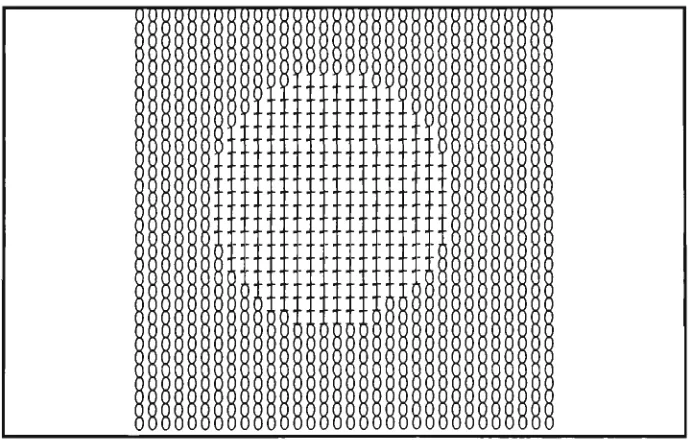
Mathematically, the most convenient way to describe this process is to consider the pbcels marked o or x in ( a ) as a set or image itself, called the structuring element. We denote it by R here. Then the result of the dilation is vsritten A®R. For the stmcturing element the origin is taken at the o pixel. Then in set notation,
A®R = {{x, y)\{x + u,y + v)&A for any (w, v ) G R)
For later generalisation to gray-scale images, an altemative formula is
{A®R){x,y)= \ g{x+u,y+v) {u,v)eR
where V denotes the logical OR of the Boolean g values.
An erosion C of a set A is defined similariy to a dilation, except that pixel {x, y) will be in C if (jf, y) and all of its neighbours are in A. For a stmcturing element R the result is written AQR. SO I '
AeR^ {{x, y)\ {x + u, y + v) G A for a\\ {u, v) E R)
or equivalently,
{AeR){x,y)= A g{x+u,y+v) {u,v)eR
Where A denotes the logical AND.
We may consider the stmcturing element as a mask. The origin of the mask is moved to each pixel in turn and that pixel is considered part of the dilation of A if the stmcturing element touches A. It is considered part of the erosion of A if the stmcturing element lies entirely inside A. In the example shown in Fig. 4.1, the stmcturing element can nowhere fit inside A, so the erosion of A in that case is the null set.
The complement of a set A (denoted by .4 ) is the set of points in the universal set W but not in A. Clearly dilating a set has the effect of eroding its complement. More precisely
AeR=A®R
^= {(X, y) I {-X, -y) G R}
More generally, a morphological operation is some logical combination of the Boolean values g(x+u, y+v) where {u, v) ranges over the stmcturing element. In general we drop the requirement that the origin is in the stmcturing element. Different stmcturing elements address different concerns. For example, a 3-by-3 square stmcturing element can be used to eliminate a round comer in a shape, and a stmcturing element in the form of a thin line can be used in the processing of striated textures.
4.2 History of image algebra
Serra and Sternberg were the first to unify morphological concepts and methods into a coherent algebraic theory specifically designed for image processing and image analysis. Sternberg was also the first to use the term image algebra [STER80]. More recently, P. Maragos introduced a new image algebra unifying a large class of linear and non-linear systems under the theory of mathematical morphology [MARA85].
G.X. Ritter et al introduced Air Force Armament Laboratory (AFATL) Standard Image Algebra [RITT90]. This algebra provides a common mathematical environment for image-processing algorithm development and methodologies for algorithm optimisation, comparison and performance evaluation. In addition, the image algebra provides a powerfiil algebraic language for image processing which, if properly embedded into high level programming, will greatly increase a programmer's productivity as programming tasks are greatly simplified due to replacement of large blocks of code by short algebraic statements.
Another algebraic stmcture with the same goals as the AFATAL image algebra is the algebra described by Giardina and Dougherty [DOUG87]. It also defines a set of basic or primitive image operations.
4.3 Huang's image algebra
Huang's image algebra provides a decomposition of general operations, including low-level image processing operations, into three fundamental operations. The parallelism of these fundamental operations makes them suitable for expression in terms of the bit block-transfer operations in Smalltalk.
4.3.1 Two principles and the basic elements
Huang proved his two fundamental principles that basically define the BIA. They
are:-Principle 1.
Fundamental Principle of Image Transformations
Any binary image morphology transformation T can be implemented by using an appropriate reference image R and the three fimdamental operations (details in next
section):-1. Complement of an image. 2. Union of two images.
3. Dilation of an image using a reference image.
Principle 2.
Fundamental Principle of Reference Images R
Any reference image R can be generated from elementary images (I, A, A' 1, B, B"l) by using the three flindamental operations.
are:-/ = 1(0,0)}
A = {(1,0)}
A-^= {(-1,0)} B={{0,1)} B-^= {(0,-1)}
consisting of an image point at the origin consisting of an image point right of the origin consisting of an image point left of the origin consisting of an image point above of the origin consisting of an image point below of the origin
Table 4.1 Five basic elements
For example, we can define a 4-connected reference image
thus:-N.=I^AUA-'KJB^B-^
Huang defined 4-connected and 8-connected as
follows:-Two image points (x,v) and |ij) of an image are 4-connected <-> there exists a sequence of image points {X,V) = (XO,YO), ( X I , Y I ) , ..., (Xm/Vm> =(i,i), where (X|^,yi^) is a 4-neighbour of (^\^.^,'V\i.'\) and {x^^,y^JeX, 1 ^ l < ^ m .
Two image points (x.y) and (i,j) of an image are 8-connected <^ there exists a sequence of image points (x,y) = (xo,yo), (x^.V^), •/ (Xm'Vm) =(iJ)r where (x,^,Vi^) is a 8-neighbour of (xi^.i/Vi^.^) and |X|^,y|^)eX, l ^ k ^ m .
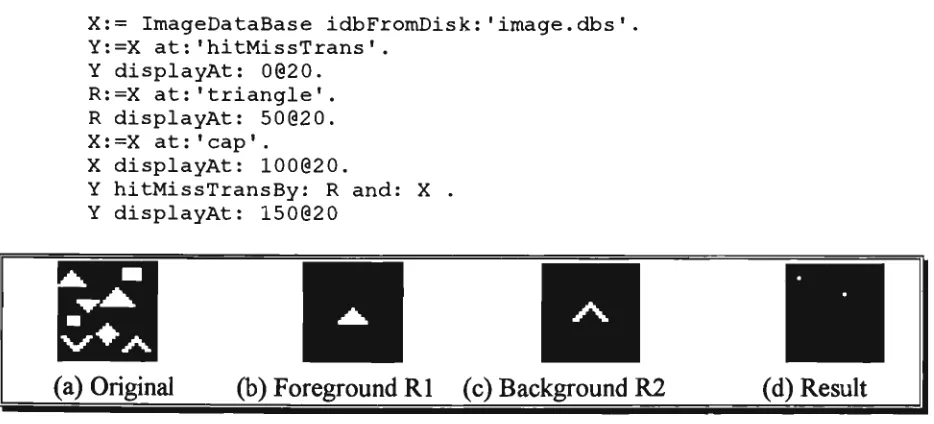
Other operations such as opening, closing, thinning and thickening can be expressed in terms of three basic operations to be defined in the next section.
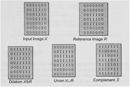
4.3.2 Three basic operations
Huang's binary-image algebra (BIA) expresses general operations on binary-images in terms of three fundamental
operations:-1. Complement of an image X.
X = {{x,y)\(x,y)eWA(x,y)^X}
2. Union of two images X and R.
3. Dilation of an image X with a reference image R.
X e R={{x\ + x2,y\+y2) &W\{x\,y\) &X,{x2,y2) GR}
Following are some examples of the three basic operations
:-Q O O O O O O
o o n 110
0 0 0 1 1 1 0 0 0 0 0 1 1 0 0 0 0 0 0 1 0 0 0 0 0 0 0 0 0 0 0 0 0 0 0
Input Image X
011 n n
0 1 1 1 1 1 1 0 t 11 1 11001 n u
0 0 0 1 1 1 1 0 0 0 0 1 1 1 0 0 0 0 0 0 0
o o o o o o o
0 0 0 0 0 0 0 0 0 1 1 10 0 0 0 1 1 1 0 0
0 0 1 1 1 0 0 0 0 0 0 0 0 0 0 0 0 0 0 0 0
Reference Image R
0 0 0 0 0 0 0 0 0 1 1 1 1 0 0 0 1 1 1 1 0 0 0 1 1 1 1 0
0 0 1 I i 1 0
0 0 0 0 0 0 0
0 0 0 0 0 0 0
1 1 1 1 1 1
1 0 0 0 0 1 1 10 0 0 1 1 n 0 0 1
1 1 n o i
l i n n
n n n
Dilation X e R Union X u R Complement X
Fig. 4.2 The three basic operations
In the following operations and in section 4.3.3, each operation is implemented by an instance method of the class Image. In conformance with Smalltalk convention, we use the comment to make it clear whether we are changing the receiver and returning it, or whether we are returning a new instance of Image. In Smalltalk the default return is self, that is, the receiver. In the following methods, we are changing the receiver.
We may implement the fiandamental operations in SmalltalkA^286 by means of the following instance
methods:-complement
"Answer the complement of an image. "
union:imageR
"Answer an image containing the image of the union of imageR and the receiver imageX. "
self copy: (0@0 extent:(imageR extent)) from:imageR to:0@0 rule:? .
d i l a t i o n B y : i m a g e R
" D i l a t i o n of an image (imageX) by a r e f e r e n c e image (imageR) "
I a b c|
b:= (Image width: (self width) height: (self height)) black. c:= (Image width: (self width) height: (self height)) black. a:= OrderedCollection new.
a:= imageR getPointsFrom:imageR. 1 to: a size do:[:il
b copy: (000 extent:(self extent)) from:self to:((a at:i)- (imageR centre)) rule:3. c union:b
] .
self copy: (0@0 extent:(self extent)) from:c to:0@0 rule:3
4.3.3 Other operations
In this section, we give other operations which are derived fi^om the three basic operations, together with their Smalltalk implementations and test-scripts. To illustrate each operation we use small sample images, which we created by using the small-image database environment to be described in the next chapter, rather than real-world xmdLgQS. [In this section, Smalltalk refers to SmalltalkA^286.]
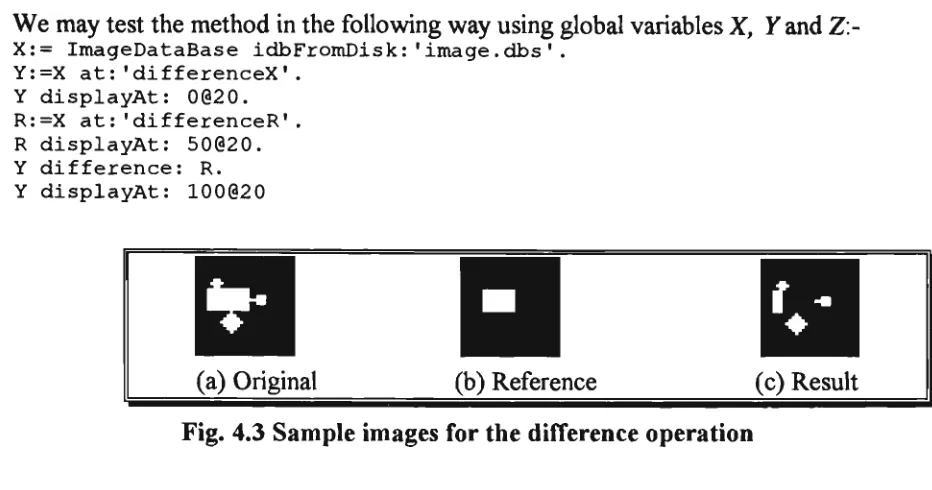
Difference
The difference is one of the standard operations. If i? is a template or ideal image and X is the actual image then X/R shows defects in X by showing the extra pixels that X
contains. Huang's expression for the difference of an image X by an image R is given in his Formula
4.1:-XI R^{(^x,y)\{x,y)eX A{x,y)^R}
We may implement the operation in Smalltalk by means of the followdng instance method
:-difference:imageR
((self complement) union: imageR ) complement
We may test the method in the following way using global variables X, Y and Z:
X:= ImageDataBase idbFromDisk:'image.dbs'. Y:=X at:'differenceX'.
Y displayAt: 0(320. R:=X at:'differenceR'. R displayAt: 50020. Y difference: R. Y displayAt: 100020
(a) Original (b) Reference (c) Result Fig. 4.3 Sample images for the difference operation
I n t e r s e c t i o n
The intersection operation is the parallel form of Boolean AND. Huang's expression for the intersection of an image A'by an image R is given in his Formula 4.2
:-Xr^R= {{x,y) GXA{x,y) GR= Xy^R
We may implement the operation in Smalltalk by means of the foUovsdng instance
method:-i n t e r s e c t method:-i o n : method:-i m a g e R
"Answer an image that contains the intersection of original image (imageX) and reference image (imageR)"
((self complement) union:(imageR complement)) complement
Although we do not give the script, this, and following operations may be tested in the same way as the preceding operation.
c
(a) Original3
E r o s i o n
Erosion is the morphological dual to dilation. It is the morphological transformation which combines two sets using the vector subtraction of set elements. In general, the erosion of an image Zby a reference image R can be used to remove pixels around the boundary of regions and so decrease their size, increase the size of holes, eliminate regions and break bridges in X. Huang's expression for the erosion of an image X by an image R is given in his Formula 4.3
:-xeR = :-xeR
We may implement the operation in Smalltalk by means of the following instance method
:-erosionBy:imageR
"Answer an image that containing the erosion of original image (imageX) by reference image (imageR)"
((self complement) dilationBy:(imageR reflect)) complement
We may test erosionBy: in the same way as before.
(a) Original (b) Reference (c) Result
Fig. 4.5 Sample images for the erosion operation
Symmetric Difference
The symmetric difference operation is the parallel form of the Boolean Exclusive-OR. It is a commutative operation and its inverse operation is itself If 7? is a template then XlsR indicates all the discrepancies between X and that template and so detects defects in X. Huang's expression for the symmetric difference of an image X by an image R is given in his Formula 4.4
We may implement the operation in Smalltalk by means of the following instance
method:-syrametricDiff:imageR
"Answer an image which i s t h e symmetric d i f f e r e n c e between o r i g i n a l image (imageX) and r e f e r e n c e image (imageR) "
I a b I
a:= (Image width: (self width) height: (self height)) black. a copy: (000 extent:(self extent)) from:self to:O0O rule:3. a difference:imageR.
b:= (Image width: (self width) height: (self height)) black. b copy: (000 extent: (self extent)) fromiself to:Oi@0 rule:3.
imageR difference:b. a union:imageR.
self copy: (000 extent:(self extent)) from:a to:O0O rule:3
We may test symmetricDiff: in the same way as before.
(a) Original (b) Reference (c) Result
Fig. 4.6 Sample images for the symmetric difTerence operation
Opening
Opening of images X and R is simply the erosion of A'by R, followed by a dilation of the result by R. We can interpret opening as moving the stmcturing element around inside the foreground of the image. Those parts that the stmcturing elements can reach are preserved. Opening generally smooths the contours of an image, breaks narrow isthmuses and eliminates thin protmsions. Huang's expression for the opening of an image Jf by an image R is given in his Formula 4.5
:-XOR = {XBR)®R = X®R®R
We may implement the operation in Smalltalk by means of the following instance method
:-openingBy:imageR
[self erosionBy:imageR) dilationBy:imageR
We may test openingBy: in the same way as before.
n
(a) Original (b) Reference (c) Result
Fig. 4.7 Sample images for the open operation
C l o s i n g
The closing of images A'and R is simply the dilation of A'by R, followed by an erosion of the result by R. We can interpret closing as moving the reference image around in the background of the image. Those parts of the image that are not reached by the reference image consititue the closing. Closing tends to smooth sections of contours but, as opposed to opening, it generally fijses narrow breaks and long thin gulfs, eliminates small holes and fills gaps in the contour. Huang's expression for the closing of an image Xhy an image R is given in his Formula 4.6
:-X»R = {X®R)e R = {X®R)®R
We may implement the operation in Smalltalk by means of the following instance
method:-closingBy:imageR
"The closing operation is an dilation followed by an erosion with the same reference imageR. "
(self dilationBy:imageR) erosionBy:imageR
We may test closingBy: in the same way as before.
Ill
(a) Original (b) Reference
III
(c) Result