Alleviation of Lower Order Harmonics in a
Single Phase Photo Voltaic Inverter
Connected To Grid
K.Kavitha
1, S.Ramesh
2PG Student [PE&ED], Dept. of EEE, Siddartha Institute of Science and Technology, Puttur, Andhra pradesh, India1
Associate professor, Dept. of EEE, Siddartha Institute of Science and Technology, Puttur, Andhra pradesh, India 2
ABSTRACT: Generally the Power circuit topology of the single phase PV system will be a good choice for low-rated
photo voltaic inverters of rating less than a kilowatt. In the ideal case the system will not have any lower order harmonics. However, some dominant factors result in lower order harmonics in the system such as on-state voltage drops across the switches and the distortion in the grid voltage itself etc. This dc injection into the primary of the transformer will result in even harmonics which are being drawn from the grid, again providing a lower power quality. In this work, a single-phase grid-connected photovoltaic inverter topology consists of a boost section, a low-voltage single-phase H-bridge inverter with an inductive filter, and a step-up transformer interfacing with the grid is presented. A novel design of inverter current control that attenuates the lower order harmonics is presented in this project. An adaptive harmonic compensation technique with its design is proposed for the lower order harmonic compensation. In accumulation, a proportional-resonant-integral (PRI) controller and its design is also proposed. So, in this project some modification is made in the inverter current control for a grid connected single-phase photovoltaic inverter for ensuring high quality of the current to be injected into the grid.
KEYWORDS: proportional-resonant-integral (PRI), photo voltaic inverters, adaptive harmonic compensation,
inductive filter.
I.INTRODUCTION
Now a days energy demand has been increasing day to day as the standard of living of people of any country is proportional to the energy consumption made by them. We know that basically there are two types of energy sources namely conventional energy sources and renewable energy sources. Renewable energy sources like solar, wind, and geothermal became popular due to the depletion of conventional energy sources. Hence, many distributed generation (DG) systems making use of the renewable energy sources are being designed and connected to a grid. In this work, one such Distributed Generation system with solar energy as the source is considered. The solar inverter system topology consists of the following three power circuit stages as shown in figure1.
The switches in Fig. 1 are rated for the low voltage which results in reduction of cost, the component count will be reduced and the overall reliability of the system increases. The above circuit comprises of a low voltage inverter with 40v dc bus connected to 230v grid using step up transformer. This topology consists of a PV array which is a combination of eight PV panels; each panel consists of three modules and it is a good choice for low-rated PV inverters of rating less than a kilowatt. When compared to the other systems this topology has a relatively larger size of the interface transformer which is a disadvantage. Other topologies consist of a high-frequency link transformer. There can be a dc injection into the transformer primary due to a number of reasons. They are varying power reference from a fast MPPT block from which the ac current reference is generated which is given as reference for error detection, the offsets in the sensors, and A/D conversion block in the digital controller. This dc injection would result in even harmonics being drawn from the grid.
ISSN (Print) : 2320 – 3765 ISSN (Online): 2278 – 8875
I
nternational
J
ournal of
A
dvanced
R
esearch in
E
lectrical,
E
lectronics and
I
nstrumentation
E
ngineering
(An ISO 3297: 2007 Certified Organization)
Vol. 3, Issue 9, September 2014
Fig1: Power circuit topology of the 1 − φ PV system for a low-voltage inverter
It is important to attenuate these lower order harmonics in order for the PV inverter to meet standards such as IEEE 519-1992 and IEEE 1547-2003. Hence, In this work we concentrate on the design of the inverter current control in
order to achieve a good attenuation of the lower order harmonics. It must be observed that attenuating the lower order
harmonics using a larger output filter inductance is not good because it increases losses in the system along with a larger fundamental voltage drop and cost will be increased. This work includes an analysis to design the value of the gain in the proportional resonant controller to achieve an adequate level of harmonic compensation. With the help of this scheme overall system dynamics is also analysed. Adaptive filter method is simple for implementation and hence it can be implemented in a low-end digital controller.
A. LITERATURE SURVEY
This requirements and recommended practices are applied to all types of static power converters used in industrial and commercial power systems [7]. The troubles involved in the harmonic control and reactive compensation of such converters are covered, and an application guide is rendered. Confines of disturbances to the ac power distribution system that affect other equipment and communications are recommended. This is not intended to cover the effect of radio frequency interference. In reality, however, any solid-state switching device has a finite switching time, and the turn-off time of the device is of particular importance in most applications. In inverters, the finite turn-off time may cause a short circuit of the dc link at the instant of switchover between the two elements connected in series across the
dc link [2].The 1547 standard focuses on the technical provision for, and the testing of, the interconnection itself. IEEE
1547 offers power engineers and other stakeholders a broad-based tool to help realize the grid of the future with various forms of DR effectively contributing to our electricity needs. Traditionally, utility EPSs were not designed to accommodate active generation and storage at the distribution level [8].
II.ORIGIN OF LOWER ORDER HARMONICS
A. ODD HARMONICS
Fig.2: Generation of an inverter ac current reference from an MPPT block.
The dead-time effect introduces lower order harmonics which are proportional to the dead time, switching frequency, and the dc bus voltage. The dead-time effect for each leg of the inverter can be modelled as a square wave error voltage out of phase with the current at the pole of the leg. The device drops also will cause a similar effect but the resulting amount of distortion is smaller compared to that due to the dead time. Thus, for a single-phase inverter topology considered, net error voltage is the voltage between the poles and is out of phase with the primary current of the transformer. Using the values of the filter inductance, transformer leakage inductance, and the net series resistance, the harmonic current magnitudes can be evaluated. Again, it must be noted that the phase angle of the harmonic currents in this case will be 180◦ for UPF operation. Thus, it can be observed that the net harmonic content will have some phase angle with respect to the fundamental current depending on the relative magnitudes of the distortions due to the magnetizing current and the dead time.
B. EVEN HARMONICS
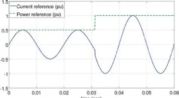
The topology under consideration is very sensitive to the presence of dc offset in the inverter terminal voltage. The dc offset can enter from a number of factors such as varying power reference given by a fast MPPT block, the offsets in the A/D converter, and the sensors. To understand how a fast MPPT introduces a dc offset, consider Figs. 2 and 3. In
Figure. 2, dboost is the duty ratio command given to the boost converter switch, Vpv and ipv are the panel voltage and
current, respectively, Ppv is the panel output power, Vg is the rms value of the grid voltage, sin θ is the in-phase unit vector for the grid voltage, and i* is the reference to the current control loop from an MPPT block. As the power reference keeps on changing due to fast MPPT action, the current reference may have a nonzero average value, which is illustrated in Fig. 3 for a step change in power reference which repeats.
Fig.3. Occurrence of nonzero average in current reference due to a fast changing power reference.
III PROJECTED TOPOLOGIES
A .INTRODUCTION TO THE PRI CONTROLLER
Conventional stationary reference frame control consists of a PR controller to generate the inverter voltage reference. In
this work, a alteration to the PR controller is projected, by adding an integral block, GI as indicated in Fig.4. The
ISSN (Print) : 2320 – 3765 ISSN (Online): 2278 – 8875
I
nternational
J
ournal of
A
dvanced
R
esearch in
E
lectrical,
E
lectronics and
I
nstrumentation
E
ngineering
(An ISO 3297: 2007 Certified Organization)
Vol. 3, Issue 9, September 2014
The inverter will have a gain of to the voltage reference generated by the controller and the impedance offered is given by (Rs + SLs) in s-domain. Rs and Ls are the net resistance and inductance referred to the primary side of the
transformer, respectively. Ls includes the filter inductance and the leakage inductance of the transformer. Rs is the net
series resistance due to the filter inductor and the transformer. The PRI controller is proposed to ensure that the output current of the system does not contain any dc offset.
Fig.4. Block diagram of the fundamental current control with the PRI controller
The PRI controller introduces a zero at s = 0 in the closed-loop transfer function. Hence, the output current will not contain any steady state dc offset. This is necessary in the topology considered because the presence of a dc offset would result in a flow of even harmonics. The following section explains the design of PR controller parameters and proposes a systematic method of selecting and tuning the gain of the integral block in the PRI controller.
Fig.5. Complete ac current control structure of the inverter.
B. COMPLETE CURRENT CONTROL STRUCTURE
The overall current control block diagram with the adaptive compensation is shown in Fig.5. Note that the fundamental current control is done using the transformer primary current and the harmonic compensation block uses the secondary current, which is the current injected into the grid. Fig.5 shows only one adaptive harmonic compensation block for the
kth harmonic. If say dominant harmonics third, fifth, and seventh need to be attenuated, then three adaptive filters and
three gain terms kadapt are required and the net voltage reference added to the output of the PRI controller will be the
Fig.6 Structure of a generalized adaptive filter with adaptation weights wi .
Thus, depending on the number of harmonics to be attenuated, the number of blocks can be selected. Observe that n in
Fig.5 is the transformer turns ratio from secondary to primary. isec,k,t is the net kth harmonic current in the secondary,
which is estimated using the LMS adaptive filter. This is mainly due to the harmonics in the magnetizing current and the dead-time effect. A single-phase PLL is used to generate the reference sine–cosine signals synchronized with the
grid voltage for the adaptive filter. Next, computation of the adaptive gain kadapt is discussed.
Fig.7. Block diagram of adaptive estimation of a particular harmonic of grid current.
Based on the estimated net kth harmonic in the grid current, the voltage reference Vk,ref is generated by multiplying the
estimated harmonic with kadapt. The effect of this voltage reference is that it results in an amplified voltage at that
ISSN (Print) : 2320 – 3765 ISSN (Online): 2278 – 8875
I
nternational
J
ournal of
A
dvanced
R
esearch in
E
lectrical,
E
lectronics and
I
nstrumentation
E
ngineering
(An ISO 3297: 2007 Certified Organization)
Vol. 3, Issue 9, September 2014
IV.SIMULATION RESULTS
Fig 8: simulation circuit for proportional resonant integral controller and LMS adaptive filter
Figure 8 represents the simulation circuit for the proposed system which includes both the proportional controller and LMS adaptive filter are present and we can view the results through the scope in the simulation circuit.
Fig 9: simulation waveforms for the circuit with PRI controller and LMS adaptive filter
Figure 9 represents the waveforms for the grid current and primary current along with the voltage of grid. we can observe the purity of the waveforms in the figure.
Figure 10: Fast Fourier Transform analysis of grid current
Fig 11: simulation circuit for fuzzy controller and control and LMS adaptive filter
Figure 11 represents the simulation circuit for the system which includes both the fuzzy controller and the LMS adaptive filter. Here fuzzy controller is used instead of the proportional resonant controller. It is the extended circuit to the circuit present in the figure 8.
Fig 12: simulation waveforms for the circuit with fuzzy controller and LMs adaptive filter
Figure 12 represents the waveforms for the grid current, primary current and the voltage of grid. The distortion current Of the grid is almost reduced
Fig13: FFT analysis of grid current
ISSN (Print) : 2320 – 3765 ISSN (Online): 2278 – 8875
I
nternational
J
ournal of
A
dvanced
R
esearch in
E
lectrical,
E
lectronics and
I
nstrumentation
E
ngineering
(An ISO 3297: 2007 Certified Organization)
Vol. 3, Issue 9, September 2014
V.CONCLUSION
Modification to the inverter current control for a grid connected single-phase photovoltaic inverter has been proposed in this work, for ensuring high quality of the current injected into the grid. The proposed method uses an LMS adaptive filter to estimate a particular harmonic in the grid current that needs to be attenuated. The design of the gain of a proportional controller to have an adequate harmonic compensation has been explained. To evade dc biasing of the transformer, a novel Proportional Resonant Integral controller has been proposed and its design has been presented. The PRI controller and the adaptive compensation scheme together improve the quality of the current injected into the grid.
REFERENCES
1. S. B. Kjaer, J. K. Pedersen, and F. Blaabjerg, “A review of single-phase grid-connected inverters for photovoltaic modules,” IEEE Trans. Ind.Appl., vol. 41, no. 5, pp. 1292–1306, Sep./Oct. 2005.
2. S.-G. Jeung and M.-H. Park, “The analysis and compensation of dead time effects in PWM inverters,” IEEE Trans. Ind. Electron., vol. 38, no. 2, pp. 108–114, Apr. 1991.
3. J.-W. Choi and S.-K. Sul, “A new compensation strategy reducing voltage/ current distortion in PWM VSI systems operating with low output voltages,” IEEE Trans. Ind. Appl., vol. 31, no. 5, pp. 1001–1008, Sep./Oct. 1995.
4. R.Mu˜noz and T. A. Lipo, “On-line dead-time compensation technique for open-loop PWM-VSI drives,” IEEE Trans. Power Electron., vol. 14, no. 4, pp. 683–689, Jul. 1999.
5. C. Oliveira, C. B. Jacobina, and A. M. N. Lima, “Improved dead-time compensation for sinusoidal PWM inverters operating at high switching frequencies,” IEEE Trans. Ind. Electron., vol. 54, no. 4, pp. 2295–2304, Aug. 2007.
6. L. Chen and F. Z. Peng, “Dead-time elimination for voltage source inverters,”IEEE Trans. Power Electron., vol. 23, no. 2, pp. 574–580, Mar.2008.
7. IEEE Recommended Practices and Requirements for Harmonic Control in Electrical Power Systems, IEEE Standard 519-1992, 1992. 8. IEEE Standard for Interconnecting Distributed Resources With the Electric Power System, IEEE Standard 1547-2003, 2003.
9. T. Esram and P. L. Chapman, “Comparison of photovoltaic array maximum power point tracking techniques,” IEEE Trans. Energy Convers.,vol. 22, no. 2, pp. 439–449, Jun. 2007.