Part Number 612.8001
GLX-PLUS
INSTALLATION AND
FIELD MAINTENANCE
MANUAL
Issue 2, June 1993
INTER-TEL PRACTICES TABLE OF CONTENTS GLX-PLUS INSTALLATION & MAINTENANCE Issue 2, June 1993
TABLE OF CONTENTS
CONTENTS
PAGE
TABLE OF CONTENTS
. . .
111. . .
LIST OF FIGURES . . .
VFCC REGULATIONS . . . vii
SAFETY REGULATIONS . . . ix
LIMITED WARRANTY . . .
XOVERVIEW ...
1. Introduction ...
2. Hardware Summary ...
3. Installation, Programming, And Maintenance Summary ...
4. Features Summary ...
...
...
SPECIFICATIONS ...
1. Introduction ...
...
2. Cabling And The Main Distribution Frame (MDF) ...
3. Key Service Unit (KSU) ...
4. Station Instruments ...
5. Optional System Equipment ...
INSTALLATION ...
1. Introduction ...
...
2. System Installation Outline ...
3. Pre-Installation Checklist . . ...
4. Station Cabling And Terminations ...
5. Terminating CO Lines At The MDF
...
6. KSU Installation ...
7. Station Installation ...
8. External Paging Equipment Installation ...
9. External Music Source Installation ...
10. Battery Back-Up Equipment ...
11. Post-Installation Checklist ...
FEATURES ...
1. Introduction ...
2. Feature Keys And Codes ...
3. CO Line Features ...
4. Protection Against Power Failure ...
5. Station Instruments ...
6. SignalsAndTones
...
l-l
l-l
l-l
l-l
l-2
2-l
2-2
2-2
2-3
2-9
2-12
3-l
3-2
3-2
3-4
3-6
3-12
3-15
3-22
3-31
3-31
3-33
3-33
TABLE OF CONTENTS INTER-TEL PRACTICES Issue 2, June 1993 GLX-PLUS INSTALIATION & MAINTENANCE
CONTENTS
7. Music-On-Hold And Background Music ...
8. Intercom Calls ...
9. Outside Calls ...
10. Placing Calls On Hold ...
11. Call Waiting ...
12. Call Transfer ...
13. Call Pick-Up (Reverse Transfer) ...
14. Paging.. ...
15. Call Forwarding ...
16. Privacy Release ...
17. Call Privacy Restore (Executive Or GLX-Plus Keysets Only) ...
18. Conference Calls (Keysets Only) ...
19. Speed Dialing (Keysets Only) ...
20. Do-Not-Disturb (Keysets Only) ...
21. Redialing (Keysets Only) ...
22. Time And Date Display Programming (GLX-Plus Keysets Only) ...
23. SMDR Device Station ...
24. System Attendant Station ...
PROGRAMMING ...
1. Introduction ...
2. Program Planning Sheets ...
3. Outline For Programming New Systems ...
4. Initialize The System ...
5. Program The System And Station Features ...
TROUBLESHOOTING
...
1. Introduction ...
2. Troubleshooting Checklist ...
3. Troubleshooting Charts ...
4. Customer Support ...
5. Defective Unit Return Policy ...
REPLACEMENT PARTS ...
1. Introduction ...
2. Ordering Procedure ...
3. Replacement Parts List ...
4. Recommended Spare Parts ...
INDEX ...
PAGE
4-15
4-16
4-18
4-22
4-23
4-24
4-24
4-25
4-26
4-29
4-29
4-30
4-32
4-33
4-33
4-34
4-35
4-43
5-1
5-l
5-l
5-l
5-6
5-8
6-l
6-l
6-l
6-3
6-19
6-19
7-l
7-l
7-l
7-l
7-l
INTER-TEL PRACTICES LIST OF FIGURES GLX-PLUS INSTALLATION & MAINTENANCE Issue 2, June 1993
LIST OF FIGURES
NUMBER
TflLE
PAGE
SPECIFICATIONS
Figure 2-1.
Key Service Unit (KSU) ...
Figure 2-2.
Main Control PCB ...
Figure 2-3.
ExpansionPCB ...
..i.
Figure 2-4.
Accessory Port Module (APM) ...
Figure 2-5.
StandardKeyset ...
Figure 2-6.
Executive Keyset ...
Figure 2-7.
GLX-Plus Keyset ...
INSTALLATION
Figure 3-1.
Sample System Layout ...
3-3
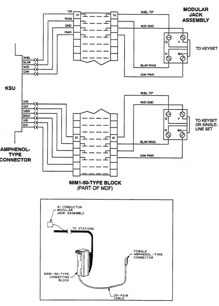
Figure 3-2.
Station Modular Jack Assembly Wiring ...
3-7
Figure 3-3.
Station Cable Terminations At The MDF ...
3-9
Figure 3-4.
Station Cable Terminations On The Station Block ...
3-10
Figure 3-5.
CO Line Terminations From RJ14 Jacks ...
3-13
Figure 3-6.
Modular Jack Assembly Wiring For CO Lines ...
3-13
Figure 3-7.
CO Line Terminations From An RJ2lX Block ...
3-14
Figure 3-8.
KSU Component Locations ...
3-15
Figure 3-9.
Install The Expansion PCB ...
3-17
Figure 3-10.
Install The APM ...
3-17
Figure 3-11.
Wall Mount The KSU ...
3-18
Figure 3-12.
KSU Grounding ...
3-19
Figure 3-13.
KSU Grounding ...
3-20
Figure 3-14.
Complete The KSU Connections ...
3-21
Figure 3-15.
GLX-Plus Keyset LCD Installation ...
3-23
Figure 3-16.
Wall Mount The Keyset ...
3-26
Figure 3-17.
GLX-Plus Keyset Data Port Module Installation ...
3-28
Figure 3-18.
LRASet-Up ...
3-29
Figure 3-19.
GLX-Plus Keyset Battery Back-Up ...
3-30
Figure 3-20.
Connect The External Equipment ...
3-32
FEATURES
Figure 4-l.
Figure 4-2.
SMDRReportFormat
...
4-37
Database Report Format ...
4-39
LIST OF FIGURES INTER-TEL PRACTICES Issue 2. June 1993 GLX-PLUS INSTALLATION & MAINTENANCE
NUMBER
TITLE
PROGRAMMING
Figure S-l.
Program Planning Sheets . . .
TROUBLESHOOTING
Figure 6-1.
Feature Troubleshooting Chart . . .
Figure 6-2.
Intercom Troubleshooting Chart . . .
Figure 6-3.
CO Line Troubleshooting Chart . . .
Figure 6-4.
Keyset Troubleshooting Chart . . .
Figure 6-5.
Single-Line Set Troubleshooting Chart . . .
Figure 6-6.
System Troubleshooting Chart . . .
REPLACEMENT PARTS
Figure 7-1.
Replacement Parts . . .
Figure 7-2.
Recommended Spare Parts . . .
PAGE
5-2
6-5
6-8
6-9
6-11
6-14
6-16
INTER-TEL PRACTICES
GLX-PLUS INSTALLATION & MAINTENANCE FCC REGULATIONS Issue 2, June 1993
FCC REGULATIONS
IMPORTANT:
1. This equipment complies with Part 68 of FCC rules. On the side of the KSU is a label that contains, among other information, the FCC registration num- ber and ringer equivalence number (REN) for this equipment. Customers connecting this equipment to the telephone network shall, before such connection is made, give notice to the telephone company of the particular line(s) to which such connection is to be made, and shall provide the telephone company with the following information:
- Complies with Part 68 of FCC rules - FCC registration no.: BE287V-15678-RF-E - Quantities and USOC numbers of required inter-
face jacks: RJ14 (C or W) or RJ21X - Sequence in which lines are to be connected - Ringer equivalence number (REN): 0.2A
NOTE: The REN is used to determine the quan- tity of devices which may be connected to the telephone line. Excessive RENs on the telephone line may result in the devices not ringing in re- sponse to an incoming call. In most, but not all areas, the sum of the RENs should not exceed five (5.0). To be certain of the number of devices that may be connected to the line, as determined by the total RENs, contact the telephone compa- ny to determine the maximum REN for the call- ing area.
- Facility interface code (FIG) by position: 02LS2 The telephone company should also be given notice upon final disconnection of this equipment from the particular line(s).
It is also the responsibility of the customer to provide the telephone company with registration numbers of any other devices which are configured for connec- tion to the telephone network.
2. This equipment cannot be used on public coin ser- vice provided by the telephone company. Connec- tion to party line service is subject to state tariffs. (Contact the state public utility commission, public service commission, or corporation commission for information.)
3. If this equipment causes harm to the telephone net- work, the telephone company will notify the cus- tomer in advance that service may be temporarily
discontinued. But if advance notice is not practical, the telephone company will notify the customer as socn as possible. Also, the customer will be advised of the right to file a complaint with the FCC, if neces- sary.
4. The telephone company may make changes in its fa- cilities, equipment, operations, or procedures which may affect the operation of this equipment. If so, the customer shall be given advance notice so that any necessary modifications can be made in order to maintain uninterrupted service.
5. If trouble is experienced with this equipment, con- tact a local.authorized factory service representative for repairs and/or warranty information. The cus- tomer, users, and unauthorized technicians should not repair, make adjustments to, or attempt to ser- vice this equipment in any way.
In the event of trouble with the telephone line(s), this equipment must be disconnected from the telephone line(s). If trouble ceases, the equipment must be re- paired by an authorized factory service representa- tive. If the trouble continues to occur with the equipment disconnected, the telephone company should be notified that they have a problem. If this is the case, repairs or adjustments made by the tele- phone company will be made at their expense.
NOTICE
THE TELEPHONE INSTRUMENTS SPECIFICALLY DESIGNED FOR THIS SYSTEM HAVE HEARING- AID COMPATIBLE HANDSETS THAI ARE IN COMPLIANCE WITH SECTION 68.316 OF THE FCC RULES.
WARNING:
FCC REGULATIONS
Issue 2, June 1993 GLX-PLUS INSTALLATION INTER-TEL & MAINTENANCE PRACTICES
- Reorient the receiving antenna
- Relocate the KSU with respect to the receiver - Check that the KSU and receiver are not on the same
circuit; the KSU must be powered from an isolated, dedicated AC outlet
If necessary, the user should consult the dealer or an ex- perienced radio/television technician for additional suggestions. The user may find the following booklet
prepared by the Federal Communications Commission helpful:
“How to Identify and Resolve Radio-TV Interference Problems”
This booklet is available from the U.S. Government Printing O&e, Washington, D.C. 20402, Stock No. 004-000-00398-5.
INTER-TEL PRACTICES
GLX-PLUS INSTALLATION & MAINTENANCE SAFETY REGULATIONS Issue 2, June 1993
SAFETY REGULATIONS
The GLX-Plus System is listed by Underwriters Laboratories Inc. (UL) as meeting the Product Safe- ty Requirements of UL 1459, Standard for Tele- phone Equipment. UL is approved by the Occupa- tional Health and Safety Administration (OSHA) as a Nationally Recognized Testing Laboratory (NRTL). Before installation, also check the local electrical codes for important information concern- ing the installation of telephone and electronic equipment.
The following safety information is reprinted from UL 1459, a product safety specification governing tele- phone equipment.
IMPORTANT
SAFETY
INSTRUCTIONS
When using your telephone equipment, basic safetypre- cautions should always be followed to reduce the risk of fire, electric shock, and injury to persons, including the following:
1. Read and understand all instructions.
2. Follow all warnings and instructions marked on the product.
3. Unplug this product from the wall outlet before cleaning. Do not use liquid cleaners or aerosol cleaners. Use a damp cloth for cleaning.
4. Do not use this product near water (for example, in a wet basement).
5. Do not place this product on an unstable cart, stand, or table. The product may fall, causing serious dam- age to the product.
6. Slots and openings in the cabinet and the back or bottom are provided for ventilation, to protect it from overheating; these openings must not be blocked or covered. This product should never be placed near or over a radiator or heat register. This product should not be placed in a built-in installa- tion unless proper ventilation is provided.
7. This product should be operated only from the type of power source indicated in the manual. If you are not sure of the type of power source to your build- ing, consult your dealer or local power company. 8. This product is equipped with a three-wire ground-
ing type plug, a plug having a third (grounding) pin. This plug will only lit into a grounding type power outlet. This is a safety feature. If you are unable to insert the plug into the outlet, contact your electri-
cian to replace your obsolete outlet. Do not defeat the safety purpose of the grounding tyPe plug. 9. Do not allow anything to rest on the power cord. Do
not locate this product where the cord will be abused by persons walking on it.
10. Do not use an extension cord with this product’s AC power cord. The AC outlet for this product should not be used for any other electrical equipment. 11. Never push objects of any kind into this product
through cabinet slots as they may touch dangerous voltage points or short out parts that could result in a risk of fire or electric shock. Never spill liquid of any kind on the product.
12. To reduce the risk of electric shock, do not disas- semble this product, but take it to a qualified serviceman when some service or repair work is re- quired. Opening or removing covers may expose you to dangerous voltages or other risks. Incorrect reassembly can cause electric shock when the prod- uct is subsequently used.
13. Unplug this Product from the wall outlet and refer servicing to qualified service personnel under the following conditions:
A. When the power supply cord or plug is dam- aged or frayed.
B. If liquid has been spilled into the product. C. If the product has been exposed to rain or wa-
ter.
D. If the product does not operate normally by fol- lowing the operating instructions. Adjust only those controls that are covered by the operating
instructions because improper adjustment of other controls may result in damage and will often require extensive work by a qualified technician to restore the product to normal op- eration.
E. If the product has been dropped or the cabinet has been damaged.
F. If the Product exhibits a distinct change in per- formance.
14. Avoid using a telephone (other than a cordless type) during an electrical storm. There may be a remote risk of electric shock from lightning.
15. Do not use the telephone to report a gas leak in the vicinity of the leak.
WARRANTY Issue 2, June 1993
INTER-TEL PRACTICES GLX-PLUS INSTALLATION & MAINTENANCE
LIMITED
W-Y
For a period of one (1) year from the date of shipment to Buyer, INTER-TEL warrants the Equipment (except for fuses and lamps) to bc free from defects in material, workmanship, or both, and to comply with specifica- tions for the Equipment, as set forth in the Installation and Field Maintenance Manual. Buyer’s sole and ex- clusive remedy for breach of this Limited Warranty shall be to have the defective Equipment (or parts) re- paired or replaced at INTER-TEL’s option. Shipping costs incurred returning warranty work to INTER-TEL shall be paid for by the Buyer. This Limited Warranty extends only to the Buyer, not b zny customer, user, or third party. This Limited Warranty does not apply to Equipment (or parts) damaged by improper handling, normal wear and tear, accidents, lightning damage, neg- ligence, or improper use or maintenance, and does not apply to Equipment altered without authorization by INTER-TEL. This Limited Warranty does not extend to any claims, suits, damages, liabilities, costs, and ex- penses arising from any act, action, or inaction of Buyer. Although the Moss-Magnuson Act should not apply, in the event that it is held to apply by a court of competent jurisdiction, the implied warranty of fitness for a par- ticular purpose shall extend for the one-year (l-year) period from the date that the Equipment was shipped to the Buyer.
THIS Wm IS ZN LIEU OF AND EXCLUDES ALL OTHER WARRANT ZES, EXPRESS OR IMPLIED, INCLUDING, BUTNOTLZMZTED TO, THE IMPLIED
WARRANTY OF MERC- ZLZTY OR FZXVESS FOR A PARTZCW PURPOSE. THERE ARE NO
WARRANTIES IK7ZCH EXTEND BEYOND THIS LZM- ZTED WARRANTI! ZN NO EVENTSHALL ZNTER-TEL
BE LL4BLE FOR LOSS OF ANTICIPATED PROFITS,
ZNCZDENI4L OR CONSEQUENTZAL DAibXGES,
LOSS OF TIME OR OTHER LOSSES INCURRED BY BUYER ZN CONNECTION WITH THE PURPOSE, POSSESSION, OPERATION, OR USE OF THE
EQUZPMEm SUCH CLAIMS BEZNG EXPRESSLY
WANED BY THE ZNSiXLLZNG COMPANI!
For complete information on returning equip ment, refer to the current Inter-Tel Incorporated
INTER-TEL PRACTICES
GLX-PLUS INSTALLATION & MAINTENANCE
OVERVIEW Issue 2, June 1993
OVERVIEW
CONTENTS
1. Introduction ...
l-l
2. Hardware Summary ...
l-l
3. Installation, Programming, And Maintenance Summary ...
l-l
4. Features Summary ...
l-2
A. System Features ...
l-2
B. Keyset Features ...
l-2
C. Single-Line Features ...
l-3
D. Attendant Features ...
l-3
E. Maximum Capacities ...
l-3
1. INTRODUCTION
3. INS’JALLATION, PROGRAMMING,
1.1 The Inter-Tel GLX-Plus System is a versatile, electronic key telephone system designed to meet the needs of small businesses. The system is easy to install and maintain, and it offers a variety of features usually found on more expensive systems. Highlights of the sys- tem’s design include:
0 Advanced microprocessor technology
l Flexible programming to customize many system
and station features
0 Capacity for up to six central office (CO) lines, 12 keysets (or 10 keysets and two single-line devices), and two private intercom chamtels
2. HARDWARESUMMARY
2.1 The SPECIFICATIONS section of this manual ex- plains environmental requirements of the system, de- scribes the hardware, and gives pre-installation information. The hardware descriptions include: Key Service Unit (KSU), station instruments, and additional equipment needed for optional features.
AND MAINTENANCE SUMMARY
3.1 The modular design and self-diagnostic capabili- ties of the system facilitate installation and repair with minimal down-time. Strict quality control standards for manufacturing and thorough field testing provide the system with the reliability demanded by today’s high- technology market.
3.2 The INSTALLKI’ION section contains instruc- tions for assembling the main distribution frame (MDF) and for installing the KSU, station instruments, and oth- er optional hardware.
3.3 The PROGRAMh4lNG section describes the pro- cedures for programming the system features. After the system is installed, the flexible software allows the data- base to be customized to meet the customer’s needs. All programming is Performed through the system’s key- sets.
OVERVIEW Issue 2. June 1993
INTER-TEL PRACTICES GLX-PLUS INSTALIATION & MAINTENANCE
4. FEATURES SUMMARY
4.1 System, keyset, single-line set, and attendant fea- tures are listed below. Those features marked with an asterisk (*) require additional equipment. For complete descriptions and operating instructions, refer to the SPECIFICATIONS and FEATURES sections of this manual.
A. SYSTEM FEATURES
Hardware and General System Features
Flexible incoming ring assignments (alternate point answering)
Flexible night ringing arrangement (night ring mode)
Database battery back-up Variable system timers
l * Optional external music source l * Optional external paging equipment l * Optional system battery back-up
l * Optional repeaters for amplified CO lines l * Optional doorbox
l * Optional voice mail system or answering machine l * Optional facsimile machine
l * Optional station message detail recording (SMDR) adapter and output device (for printing station call data and database reports)
System Organization and Record Keeping Features
l Internal and external paging zones l System alarm display and reporting l * Optional SMDR and database reports Outside Call Features
l Dual-tone multi-frequency (DTMF) or dial-pulse signalling
l CO line restriction l Toll restriction
l Programmable CO hookflash l Automatic recall timers
l Day and night modes of operation l Busy CO line callback (queue) General Station Features
l Outside call waiting l Privacy release
l * Music-on-hold
l * Internal and external paging l Private intercom calls
l Intercom camp-on and call waiting 0 Night ring answer
B. KEYSET FEATURES Six line keys
Feature keys (six on Standard Keyseta, 12 on Execu- tive Keysets and GLX-Plus Keysets)
LED indications
Direction station selection/busy lamp field @SS/ BLF) keys on Executive and GLX-Plus Keysets Volume controls
NOTE: GLX-Plus Keysets, which are equipped with audio integrated module circuitry, allow the users to individually control voice and tone volume levels for intercom calls, outside calls, background music, etc.
Immediate ringing Off-hook ringing Ring intercom first
l * Handset amplifier compatible Integrated speakerphone
Handsfree answering of intercom calls
Individual hold on the Executive and GLX-Plus Keysets
Call transfer from the Executive and GLX-Plus Key- sets
Line key skipping On-hook dialing
DSS/BLF key skipping on the Executive and GLX- Plus Keysets
l * Headset compatible
l * Data device and SMDR interface on the Executive and GLX-Plus Keysets
l * Background music l Call privacy enable l Direct line key selection l System/station speed dialing l Last number redial
l System hold 0 Conference calls 0 Do-not-disturb
INTER-TEL PRACTICES OVERVIEW GLX-PLUS INSTALLATION & MAINTENANCE Issue 2, June 1993
C. SINGLE-LINE FEATURES nels and/or circuits. The features with such capacities
l Call forwarding (internal only) l Call waiting tones enable/disable l Reverse transfer
are listed in the following table.
FEATURE CAPACITY
l Programmable single-line hookflash
l Programmable intercom ring cadence (standard or
extended)
Paging zones
Internal
External :
l Programmable audio path attenuation on a port-by-
port basis (MB or 3db pad)
Conference calls
Parties per conference
Simultaneous conferences
5
2
D. ATTENDANT FEATURES
l Responds to “0” as an intercom number l Receives attendant recalls
0 System feature programming
l System night ring mode programming l System speed-dial number programming
E. MAXIMUM CAPACITIES
4.2 Some of the features have maximum capacities that are dependent on the availability of system chan-
System speed dialing
Numbers per system Digits per number
Station speed dialing
Numbers per station Digits per entry
Rediai numbers per station
Digits per number
Busy line callback (queue) requests per station
Stations camped on to a station Stations camped on to a line
30 32
9
INTER-TEL PRACTICES SPECIFICATIONS GLX-PLUS INSTALLATION & MAINTENANCE Issue 2, June 1993
1.
2.
3.
4.
5.
Introduction ...
Cabling And The Main Distribution Frame (MDF) ...
A. Station Connections ...
B. Central Office (CO) Line Connections ...
Key Service Unit (KSU) ...
A. KSU Description
...
B. Environmental Requirements
...
C. System Power Supply ...
D. Main Control Printed Circuit Board (PCB) ...
E. Expansion PCB ...
F. Accessory Port Module (APM)
...
Station Instruments
...
A. Maximum Capacities ...
B. Keysets ...
C. Single-Line Sets ...
Optional System Equipment ...
A. System Battery Back-up ...
B. Repeater Application For Amplified CO Lines ...
C. Doorbox ...
D. Answering Machine Or Voice Mail Unit ...
E. FAX Machine ...
F. Station Message Detail Recording (SMDR) Adapter And Output Device . .
1. INTRODUCTION
SPECIFICATIONS
CONTENTS
PAGE
1.1 This section of the manual describes the following GLX-Plus System hardware:
Cabling and the Main Distribution Frame - (MT
- Key Service Unit (KSU) - Station Instruments
- Optional Equipment
1.2 The GLX-Plus System has a basic capacity for three CO lines and eight keysets. Installing the optional Expansion printed circuit board (PCB) increases the system capacity to six CO lines and 12 keysets. Or, installing the optional Accessory Port Module (APM) increases the system capacity to six CO lines, 10 key- sets, and two single-line devices.
2-l
2-2
2-2
2-2
2-3
2-3
2-3
2-5
2-5
2-5
2-5
2-9
2-9
2-9
2-11
2-12
2-12
2-12
2-12
2-12
2-13
2-13
13 Avariety of station instruments can be used on the GLX-Plus System, including:
l Standard Keyseta l Executive Keysets
l GLX-Plus Keysets (display and non-display) l Industry-Standard Single-Line, Dual-Tone
Multi-Frequency (DTMF) Sets
1.4 The following optional system equipment can also be installed:
l External music source; refer to page 2-3. l External paging equipment; refer to page 2-3. l Surge/spike protector; refer to page 2-5. l System battery back-up; refer to page 2-12.
0 CO repeater application; refer to page 2-12. 0 Doorbox; refer to page 2-12.
l Voice mail or answering machine; refer to page
SPECIFICATIONS
Issue 2, June 1993 GLX-PLUS INSTALLATION INTER-TEL & MAINTENANCE PRACTICES
0 Facsimile machine; refer to page 2-13.
l Station Message Detail Recording (SMDR) Adapter
and output device, refer to page 2-13.
2. CABLING AND THE MAIN
DISTRIBUTION
FRAME (MDF)
2.1 Connections between the KSU, CO lines, and sta- tion instruments are made at the MDF. The MDF re- quires at least a 3 x 4-foot (0.9 x l.Zmeter), g-inch plywood backboard. This will allow room to mount the KSU, connecting blocks, modular jack assemblies, and any optional peripheral equipmeni.
A. STATION CONNECTIONS
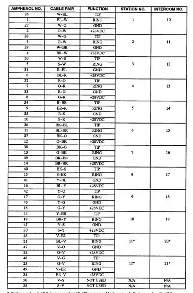
2.2 Two-pair twisted cable is run in a star (home-run) configuration from the KSU to each station location. All station cables are terminated on the 66Ml-50-type con- necting block that is mounted on the MDF backboard. The other end of each station cable is terminated on a four-conductor modular jack assembly at the station location. As an interface between the station block and the KSU, one end of a 25pair cable is terminated on the block; the other end has a female amphenol-type con- nector that attaches to the male connector on the KSU. Finally, bridging clips are installed to complete the con- nections on the block.
NOTE: To avoid possible ringing crosstalk, be sure to locate the station terminal block close to the KSU (the 25pair cable between the block and the KSU should be less than three feet in length), and do not run the station cabling for single-line devices in parallel with the sta- tion cabling for keysets.
B. CENTRAL OFFICE (CO) LINE CONNECTIONS
23 As specified in FCC Regulations, the CO lines should be terminated on telephone company RJ14 (C or W) jacks or on an RJ21X block. Three methods of termi- nating CO lines are provided in the INSTALLATION section, along with complete details about necessary supplies and procedures. The three methods are as fol- lows:
l If the CO lines are terminated on RJ14 jacks
mounted near the MDF: Using two-pair mod-to- mod line cords, every two CO lines are connected directly to the corresponding CO jacks on the KSU.
CAUTION
If the above installation method is used, the light- ning protection procedures outlined in paragraph 2.4 cannot be followed. For lightning protection ca- pability, use one of the following installation meth- ods instead.
l If the CO lines are terminated on RJ14 jacks
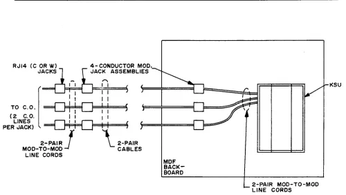
mounted away from the MDF: Using two-pair mod-to-mod line cords, every two CO lines are first terminated from the RJ14 jacks onto four-conductor modular jack assemblies mounted next to the RJ14 jacks. Then, using standard two-pair cable, the CO lines are extended to modular jack assemblies mounted on the MDF backboard. Finally, two-pair mod-to-mod line cords complete the connection from the modular jack assemblies to the correspond- ing CO jacks on the KSU. For a diagram of this method, see page 3-13.
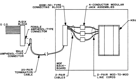
0 If the CO lines are terminated on an RJ21X block A 25pair cable terminates the CO lines from the RJ21X block onto a 66Ml-50-type connecting block on the MDF backboard. Then, for every two CO lines, two-pair cable (or cross-connect cable) is connected from the CO block to four-conductor modular jack assemblies mounted next to the KSU. Finally, two-pair mod-to-mod line cords complete the connection from the modular jack assemblies to the corresponding CO jacks on the KSU. For a dia- gram of this method, refer to page 3-14.
2.4 It is recommended that gas discharge tubes with silicon avalanche suppressors be installed on all CO lines for lightning protection. Also, in areas with fie- quent occurrences of lightning, it is recommended that the cable between the telephone company termination and the gas discharge tubes be at least 75 feet long (the cable may be coiled up if desired).
2.5 The following CO line characteristics may be re- quested by the telephone company before the system is installed.
Loss from:
CO to keyset WB (@lkHz, 0 ft.) CO to single-line set OdB (@lkHz, 0 ft.) co to co OdB (@lkHz, 0 ft.) Ringer equivalence 0.2A
Ringing voltage 4OVRMS minimum PROTECTION
INTER-TEL PRACTICES
GLX-PLUS INSTALLATION & MAINTENANCE
SPECJFICATIONS
Issue 2, June 1993
3. KEY SERVICE UNIT (KSU)
A. KSU DESCRIPTION
3.1 The KSU is a compact, wall-mounted unit that houses the system power supply, the Main Control PCB, and the optional Expansion PCB or the optional APM. The KSU performs all control and switching activities for the system, including: detecting incoming CO calls, storing speed-dial numbers, processing data-controlled
features, and controlling the interaction between key- sets, single-line sets, CO lines, and intercom channels.
Refer to the next page for a photograph of the KSU. 3.2 The system is a microprocessor-controlled, space- division switching system. The 14 audio channels in- clude:
CO lines 6
Intercom 2
Music-on-hold 2
External page 1
Conference 2
Background music 1 3.3 The KSU dimensions and weight are:
Height 15 in. (38.1 cm.) Width 11.5 in. (29.2 cm.) Depth 4.25 in. (10.8 cm.) Weight 12 lb. (5.4 kg.)
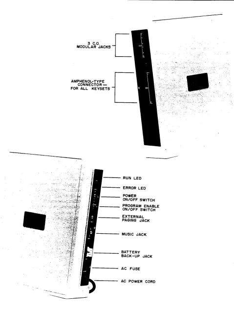
3.4 Inputs and outputs on the KSU side panels are as follows:
l Three CO line modular jacks (CO lines l-2, 3-4,
5-6) serve as inputs for two CO lines each.
l The male amphenol-type connector (STN l-12)
serves as the input for all keysets and single-line de- vices.
l The external paging jack (E-PAGE), a J&inch mini-
phone jack, is the output to a customer-provided
0
paging amplifier. For installation information, refer to page 3-31.
The music jack (an RCA-type phono jack) is the in- put for a customer-provided external music source, such as a radio, tape player, etc. For installation in- formation, refer to page 3-31.
NOTE: Current KSUs have a battery back-up jack (BAIT 3OV) that is the input for a customer-provided battery charger and/or 30V battery pack. This jack is be- ing removed on future models. In place of the battery back-up jack, Inter-Tel recommends using an uninter- ruptable Power supply (UPS) or standby power supply (SPS) unit. For additional specifications and installation information, refer to pages 2-12 and 3-33.
B. ENVIRONMENTAL REQUIREMENTS
3.5 The KSU and the station instruments require the following environmental conditions:
BFQUIREMENTS IN-
Temperature 32” to 80” F 4” to 18.5’ F WV) 0” to 26.50 c -15.5’ to 85” c Temperature 32” to 113” F -40” to 18Y F (Station Instruments) oat0 45’C -400 t0 850 c
Relative Humidity 20% to 85% 0% to 85% (Non-Condensing)
Altitude up to 10,ooo ft. up to 40,ooo ft. (3,048 m.) (12,192 m.)
SPECIFICATIONS
Issue 2, June 1993 GLX-PLUS INSTALLATION INTER-TEL & MAINTENANCE PRACTICES
FIGURE 2-l.
KEY SERVICE UNIT (KSU)
3 C.O. MODULAR JACKS
AMPHENOL-TYPE CONNECTOR - FOR ALL KEYSETS
- RUN LED I. ,. -:.-.. .’
ERROR LED POWER
ON/OFF SWITCH PROGRAM ENABLE ON/OFF SWITCH EXTERNAL
I
PAGING JACK MUSIC JACK 1INTER-TEL PRACTICES
GLX-PLUS INSTALLATION & MAINTENANCE SPECIFICATIONS Issue 2, June 1993
C. SYSTEM POWER SUPPLY
3.6 The KSU power supply, which converts the AC in- put voltage to the DC voltages required by the system, musk have an isolated, dedicated, 10%125VAC, 15A, 57-63Hz, single-phase commercial power source (for more details, refer to the first NOTE on page 3-4 in IN- STALLATION).
3.7 A 2A, 25OV, slow-blow fuse protects the system from excessive current draw. For continued system protection, replace only with a fuse of the same type and rating.
Voltage Surge and Spike Protection
3.8 To reduce the effects of AC voltage surges and spikes that may cause system malfunctions, false logic, and/or damage to the electronic components, a surge/ spike protector is recommended. Check the manufactur- er’s specifications to ensure that the surge/spike protector meets the following requirements:
l Clamp voltage transients at 300VDC within 5 nano-
seconds when exposed to waveforms as described in the ANSI/IEEE Standard C62.41-1980 (IEEE 587).
l Reduces RFI/EMI noise by at least 20dB at fiequen-
ties between 5kHz and 3OMHz.
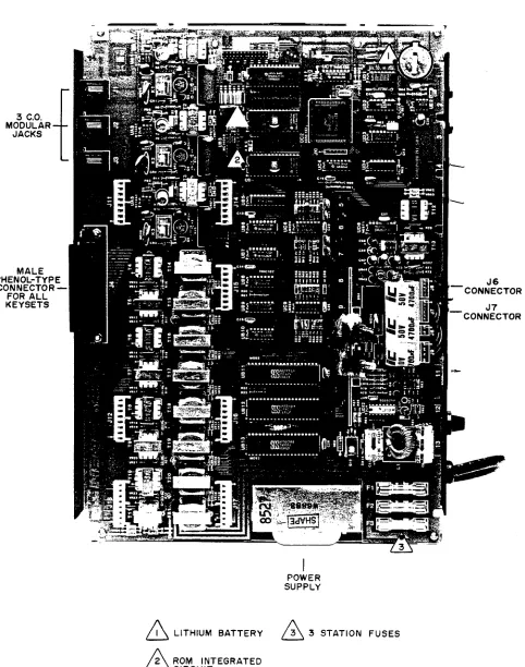
D. MAIN CONTROL PRINTED CIRCUIT BOARD (PCB)
3.9 The Main Control PCB contains the main control- ling microprocessor and its associated control logic and memory circuitry, a battery for database protection, sys- tem timers, circuitry for music-on-hold and external paging, and circuitry for three CO lines and eight key- sets. Refer to Figure 2-2 on the next page for a photograph of the PCB.
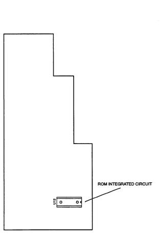
NOTE: With the current software, there is only one ROM (UB4) on the Main Control PCB.
3.10 The main Control PCB functions under the con- trol of a program that is activated when the KSU is pow- ered up. The PCB is in constant communication with the microprocessor in each keyset.
3.11 There are Sk bytes of random-access memory (RAM) and a minimum of 16k bytes of read-only memory (ROM) for use by the Main Control PCB. The software code for the main generic program is stored in the non-volatile ROM memory, and the programmed database and speed-dial numbers are stored in the RAM memory.
3.12 The RAM memory is protected by a lithium bat- tery. The battery will protect the programmed database until the accumulated system downtime exceeds one year. Under normal system use, the battery should last approximately 10 years. The PCB is shipped with a piece of paper between the battery and the battery clip to prevent any discharge until the KSU is installed. 3.13 When the system is initialized, all CO lines are configured for DTMF signalling. If necessary, some or all of the lines can be reprogrammed for dial-pulse sig- nailing through database programming.
3.14 If a customer-provided music source is installed, the music-on-hold circuitry provides two channels of music for two CO lines on hold. Refer to page 4-15 for more information. In addition, the music source can be heard through keyset speakers as background music, and camped-on intercom callers hear the music while waiting. The music-on-hold circuitry automatically holds the volume to a predetermined level that is slightly lower than normal voice volume, as required by FCC regulations. The optimum input level is l.OVRMS U’W
3.15 There are three lA, WOV, fast-acting fuses on the PCB to protect the KSU and keysets from excessive cur- rent flow. For continued protection, replace only with fuses of the same type and rating.
E. EXPANSION PCB
3.16 Circuitry for an additional three CO lines and four keyseta can be added to the Main Control PCB to expand the system’s capacity to six CO lines and 12 key- sets. The circuitry is contained on an optional Expan- sion PCB that plugs into the Main Control PCB. Refer to Figure 2-3 on page 2-7 for a photograph of the PCB.
F. ACCESSORY PORT MODULE (APM) 3.17 Circuitry for an additional three CO lines, two keysets, and two AC-ringing single-line devices can be added to the Main Control PCB to expand the system’s capacity to six CO lines, 10 keysets, and two single-line devices. The circuitry is contained on an optional APM that plugs into the Main Control PCB. Refer to Figure 2-4 on page 2-8 for a drawing of the APM.
AM
SPECIFICATIONS
Issue 2, June 1993 GLX-PLUS INSTALLATION INTER-TEL & MAINTENANCE PRACTICES
FIGURE 2-2.
MAIN CONTROL PCB
3 C.O. MODULAR. JACKS
MALE IPHENOL-TYP CONNECTOR FOR ALL KEYSETS
POWER SUPPLY
A LITHIUM BATTERY
n 3 3 STATION FUSES
SPECIFICATIONS
Issue 2, June 1993 GLX-PLUS INSTALLATION INTER-TEL % MAINTENANCE PRACTICES
FIGURE 2-4. ACCESSORY PORT MODULE (APM)
INTER-TEL PRACTICES
GLX-PLUS INSTALLATION & MAINTENANCE
SPECIFICATIONS
Issue 2, June 1993
4. STATION INSTRUMENTS
A. MAXIMUM CAPACITIES
4.1 The system capacity for stations is as follows:
Total Station Instruments 12
Keysets 1-12
Single-Line Sets o-2
B. KEYSETS
4.2 The following keyset models are available:
l Standard Keyset l Executive Keyset
l GLX-Plus Keyset (display and non-display)
NOTE: The GLX-Plus Keyset is supported only on KSUs equipped with the current 827.4012 software. 4.3 For illustrations of the keysets (showing feature keys, CO line keys, and DSS/BLF keys), refer to the drawings beginning on page 2-14.
4.4 The Standard and Executive Keyset dimensions are:
Height 3.5 in. (8.9 cm.) Width 7.5 in. (19.0 cm.) Depth 9.0 in. (22.9 cm.) Weight 2.5 lb. (1.1 kg.) 4.5 The GLX-Plus Keyset dimensions are:
Height 3.8 in. (9.7 cm.) Width 7.0 in. (17.8 cm.) Length 9.5 in. (24.1 cm.) Weight 2.5 lb. (1.1 kg.)
4.6 All keysets have the following design features: 1Zkey pushbutton keypad
Feature keys (6 on Standard Keysets, 12 on Execu- tive Keysets, and 12 on GLX-Plus Keysets) Integrated (built-in) speakerphone
Ring and voice volume controls Slide-out directory card
Reversible baseplate for wall mounting Hearing aid-compatible (HAC) handset
NOTE: GLX-Plus Keysets and handsets have been de- signed using “electret” microphone circuitry, rather than the “dynamic” microphone circuitry used on Stan- dard and Executive Keysets. Both types of keysets can be used together on the GLX-Plus System. However, if a
dynamic handset is attached to an electret keyset, the handset transmit levels will be noticeably lower. If an electret handset is attached to a dynamic keyset, the handset will not transmit.
4.7 Besides the features listed after paragraph 4.6, Executive Keysets and GLX-Plus Keysets have the fol- lowing additional features:
l 12 Direct Station Selection/Busy Lamp Field (DSS/
BLF) keys with light-emitting diode (LED) indica- tors
0 Can be equipped with either a data device (such as a personal computer equipped with a modem) or a loud ringing adapter (LRA) and an external signal- ling device (such as a loud bell, horn, flashing light, etc.)
l Can be equipped with an SMDR Adapter and output
device for generating various system reports
l VOL UP and VOL DN keys allow the user to indi-
vidually control speakerphone, handset, and ring tone volume levels (GLX-Plus Keysets only)
l Self-test feature for testing keyset functions (GLX-
Plus Keysets only)
4.8 The DSS/BLF keys on the Executive and GLX- Plus Keysets provide one-key access to any station. The lamps under the DSS/BLF keys create the busy lamp field, which indicates the status of each keyset (idle, busy, call recalling from hold, forwarding calls, in do-not-disturb, in lock-out) by different flash rates.
Integrated Speakerphone
4.9 A built-in, integrated speakerphone is standard in all keysets. It allows users to place and receive outside calls and intercom calls without lifting the handset. Once a call is connected, the keyset user may speak handsfree over the speakerphone or lift the handset to speak privately. When using the handset, the user may switch to the speakerphone by pressing the ON/OFF key and replacing the handset. If enabled, pages and/or background music may be broadcast over the speaker when the phone is not being used.
Optional Liquid Crystal Display (LCD)
SPECIFICATIONS
Issue 2. June 1993 GLX-PLUS INSTALLATION INTER-TEL & MAINTENANCE PRACTICES
number 828.1188). Other keyset models cannot be equipped with displays.
Optional Headsets
4.11 A headset may be attached to any keyset by un- plugging the handset from the handset jack on the base of the keyset, plugging the headset into the handset jack, and entering a feature code to enable the headset. The ON/OFF key, which is used to turn the headset on and off, is lit when placing and receiving calls and unlit when the headset is not in use. The Standard and Execu- tive Keysets are compatible with industry-standard, four-conductor, modular headsets that have dynamic microphones, or carbon-microphorit headsets that are connected to the keyset through an externally powered jackset (which makes the headset dynamic-compat- ible). The GLX-Plus Keyset is compatible with indus- try-standard, four-conductor, modular headsets that have electret microphones. Refer to page 3-25 for in- stallation instructions.
Optional Handset Amplifiers
4.12 Although all keyseta are equipped with hearing aid-compatible (HAC) handsets, hard-of-hearing users may wish to have an adjustable amplifier installed. An
amplifier may also be useful when the keyset is located in a noisy areas where users need to increase the receiver volume. The typical handset amplifier is an external de- vice that plugs into the keyset (where the handset is nor- mally connected); the handset is then plugged into the amplifier. Receiver voice volume is controlled by tum- ing a thumbwheel (or similar control) located on the am- plifier. Such amplifiers are generally equipped with a transformer that requires a 11OVAC outlet. Refer to page 3-25 for installation instructions.
NOTE: Due to its unique volume control circuitry, the GLX-Plus Keyset does not require a handset amplifier. 4.13 Inter-Tel recommends the Walker Universal Am- plified Handsets (standard model W6-UNI-K or noise- cancelling model W6-UNI-K-NC). These amplifiers, which are compatible with carbon, dynamic, and elec- tret microphones, are available from: Walker Bquip- ment Corporation, PO. Box M, Highway 151 South, Ringgold, Georgia 30736, (800) 426-3738 or (404) 9352600. When ordering, specify the color: ivory, black, or pearl.
Optional Data Device or LRA for Executive and GLX-Plus Keysets
4.14 The Executive Keyset has a four-conductormod- ular jack that can be used to connect eirhr a data device (such as a personal computer equipped with a modem) or a loud ringing adapter (LRA) and an external signal-
ing device (such as a loud bell, horn, flashing light, etc.) to the keyset.
4.15 GLX-Plus keyseta may be equipped with option- al Data Port Modules (part number 828.1094). The mod- ule contains a four-conductor, RI11 modular jack that can be used to connect either a data device (such as a personal computer equipped with a modem) or a loud ringing adapter (LRA) and an external signaling device (such as a loud bell, horn, flashing light, etc.) to the key- set. The Data Port Module is a source for 20-26mA of loop current. Refer to page 3-27 for instructions on in- stalling the optional Data Port Module.
4.16 Specifications for modem-equipped data de- vice: The data device must have a direct-connection modem. The modem must be externally powered (or ca- pable of operating on 20mA of loop current) and have an RI11 CO interface. The data device can be. used with the keyset to communicate with remote data equipment over voice channels being used for CO or intercom calls. Refer to pages 3-27 and 4-10 for installation and opera- tion instructions.
4.17 Specifications for loud ringing adapter (IRA): An external LRA may be connected to provide a relay for controlling external signaling devices. The LRAis connected to the keyset (or its attached Data Port Module), and the external signaling device is connected to the LRA. Refer to page 3-29 for installation instruc- tions. Each time the keyset rings, the keyset (or Data Port Module) provides 20-26mA of loop current to the LRA. This causes the LRA contacts to close and acti- vates the signaling device. The LRA is not affected by the ring tone or the ringer volume of the keyset. 4.18 The LRA device must meet the following char- acteristics.
0 Relay coil nominal draw of 20mA 0 Relay coil resistance of 100-400 ohms 0 Minimum voltage of 17VDC
0 Maximum voltage of 36VDC
0 Contact rating of 120VRMS minimum
4.19 Some types of signalling devices generate a cur- rent/voltage rating that could damage the LRA. The fol- lowing Wheelock products have been found to work properly with the GLX-Plus System.
l Wheelock DCI-24-24 is an adapter that is used with
Wheelock signaling devices.
l Wheelock CRT-D-37 is a dry contact relay that is
INTER-TEL PRACTICES
GLX-PLUS INSTALLATION & MAINTENANCE
SPECIFICATIONS Issue 2, June 1993
house, or call Wheelock directly at (201) 222-6880. In- stallation and operation instructions are included with each device.
Optional GLX-Plus Keyset Battery Rack-Up
4.21 Each GLX-Plus Keyset is equipped with its own internal clock. On display keysets, the clock can be set to show the current date and time (see page 4-34 for more information). If the keyset is unplugged or loses power, the date and time display defaults to “00 : 00
MON JAN 0 1” and must be reprogrammed.
4.22 In addition, each GLX-Plus Keyset also has VOL UP and VOL DN keys that allow the user to individually control and save speakerphone, handset, and ring tone volume levels. If the keyset is unplugged or loses power, the all saved volume levels return to the default settings. 4.23 To preserve the date and time display and the vol- ume control settings during a power interruption, each
GLX-Plus keyset may be equipped with optional battery back-up using a battery connection kit (828.1239) and a customer-provided 9V battery. The battery, when fresh, should save the date, time, and volume settings for approximately seven hours of accumulated down time. (See page 3-30 for battery installation instructions.)
C. SINGLE-LINE SETS
4.24 Up to two industry-standard, AC-ringing, single- line DTMF sets may be installed on a GLX-Plus System that is equipped with an optional APM.
NOTE: The APM is supported only on KSUs equipped with the current 827.4012 software.
SPECIFICATIONS Issue 2, June 1993
INTER-TEL PRACTICES GLX-PLUS INSTALLATION & MAINTENANCE
5. OPTIONAL SYSTEM EQUIPMENT
A. SYSTEM BAlTERY BACK-UP
5.1 To provide back-up power in the event of an AC power failure or brownout condition, the GLX-Plus Sys- tem power supply can have optional battery back-up using a customer-provided uninterruptable power sup- ply (UPS) unit or a standby power supply (SPS) unit. 5.2 The UPS or SPS unit, which is connected between the AC outlet and the KSU’s AC power cord, must have the following characteristics:
Sine wave output
Transfer time of less than 25 milliseconds (a unit with a slower switching time may result in calls be- ing dropped when back-up power is switched on) Output rating of 50 Watts
Low voltage cutoff circuit of 1OSVAC (minimum) Batteries can be internal or external
NOTE: Even if the power supply unit has the specifica- tions listed above, it cannot be guaranteed that it will work properly with the Inter-Tel GLX-Plus System. Contact Customer Support for a listing of approved UPS/SPS power supplies and installation instructions. B. REPEATER APPLICATION FOR
AMPLIFIED CO LINES
5.3 Under most circumstances, the voice volume lev- els on outside calls are quite acceptable. However, dur- ing conferences involving multiple outside parties, some reduction in voice volume may be noticed because the GLX-Plus System is a passive design system and does not amplify conferencing. To increase the voice volume levels, Inter-Tel recommends the use of one of the following “repeater” products: the Tellabs 7201 2-Wire Switched Gain Repeater or the R-TEC UMlOOO L3 Switched Gain Repeater. Both products provide from O-15 decibels of voice volume gain and allow regulation of the gain in each direction when simultane- ous voice transmission occurs. The switching sensitivity on both units is adjustable. For more information, refer to the manufacturer’s specifications provided with each product.
NOTE: Installing the repeater product on a CO line will increase the voice volume levels of all calls using that line. For this reason, it may be desirable to install the product on one CO line and then use that line mainly for establishing outside conferences.
5.4 Both products are installed at the MDF between the telephone company RJ14 jacks or RJ21X block and the KSU. When ordering a repeater unit, consult with the supplier for ordering the proper mounting shelf and
power supply for the unit. The table below outlines the connections necessary for proper installation with the GLX-Plus System.
B-TFC PtN JF’ ‘AM PIN
-Battery K 35
(-24 to -56VDc)
Ground M 17 Telco -Tip E 51 Telco -Ring H 33 System -Tip 5 41 System -Ring 7 49
5.5 Additional information on operating and adjusting the repeater unit is included with the product.
C. DOORBOX
5.6 For a doorbox application, Inter-Tel recommends the Valcom V-2901 Universal Door Answering Unit. This unit, along with the Valcom V-1070A Door Plate Speaker, is hooked up to a CO circuit on the GLX-Plus System. When a person presses a button on the door plate speaker, the unit generates ringing on the CO line. By answering the ringing line, a system user can talk with the person at the door. If the door is equipped with an electric strike plate, the system user may allow access by dialing a code or pressing an external button. To call the Valcom doorbox, the system user goes off hook and presses the line key assigned to the unit (or dials the
appropriate CO line access code).
5.7 In database programming, make sure that the de- sired keyseta have access to the CO line assigned to the Valcom unit. Also, assign CO line ring-in to the keyset that will be answering calls from the Valcom unit.
5.8 The Valcom door answering unit and talkback speaker can be ordered from a local supply house. In- stallation and operation instructions are included with the unit.
D. ANSWERING MACHINE OR VOICE MAIL 5.9 If desired, an optional answering machine or voice mail unit can be connected to an available single-line circuit on the GLX-Plus APM. Depending on the spe- cific capabilities of the unit, calls can easily be placed, transferred, or forwarded to the answering machine or voice mail unit.
INTER-TEL PRACTICES
GLX-PLUS INSTALLATION & MAINTENANCE
SPECIFICATIONS Issue 2, June 1993
ing machine is connected to the APM, it may be neces- sary to set a maximum record time.
E. FAXMACEKINE
5.11 A facsimile (FAX) machine allows the transmis- sion of a picture, drawing, or document over a standard phone line to be reproduced by another machine at the receiving end. This can be an efficient, cost-effective communication tool.
5.12 Standard installation procedures for FAX ma- chines involve connecting the machine to a dedicated line for sending and receiving documents. With a GLX- Plus System, the FAX facilities-are integrated with the telephone system. Some of the special capabilities that a GLX-Plus System can add to a FAX installation include the following:
Incoming FAX calls can be forwarded directly to a FAX machine and/or they can be answered by a sta- tion user and transferred to the FAX machine. This allows FAX calls to come in on any line; there is no need for a dedicated line.
The optional SMDR feature can help track outgoing FAX calls for billing purposes.
The GLX-Plus System is compatible with standard FAX machines; there are no special requirements. 5.13 A FAX machine can be installed on any unused APM single-line circuit, and can be assigned outgoing
lines. For more information, refer to pages 4-12 and 5-14.
F. STATION MESSAGE DETAIL
RECORDING (SMDR) ADAPTER AND OUTPUT DEVICE
5.14 If desired, an optional SMDRAdapter and output device (printer, terminal, etc.) can be connected to one Executive or one GLX-Plus Keyset. The device allows the programmer to print a variety of useful SMDR, pro- gramming, and system reports.
NOTE: If used on an Executive Keyset, the SMDR Adapter is connected to the DATA jack on the back of the keyset. If used on a GLX-Plus Keyset, the SMDR Adapter is connected to the three-pin header labeled J8 on the keyset’s control board.
5.15 The SMDR Adapter (model no. GSA232) is available from Integrated Design Services (IDS), 5737 W. Ivanhoe Street, Chandler AZ, 85226-1823, phone/ FAX (602) 961-4448.
SPECIFICATIONS Issue 2, June 1993
INTER-TEL PRACTICES GLX-PLUS INSTALLATION & MAINTENANCE
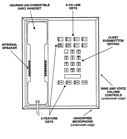
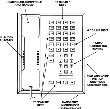
FIGURE 2-5. STANDARD KEYSET
HEARING AID-COMPATIBLE 6 CO LINE
(HAC) HANDSET KEYS
INTERNAL SPEAKER
\
T-‘
!
:
a a
l l
12-KEY PUSHBUTTON
KEY PAD
\
RING AND VOICE
VOLUME
CONTROLS
(underneath edge)
6 FEATURE KEYS
INTER-TEL PRACTICES SPECIFICATIONS GLX-PLUS INSTALLATION & MAINTENANCE Issue 2, June 1993
FIGURE 2-6. EXECUTIVE KEYSET
HEARING AID-COMPATIBLE 12 DSS/BLF
(HAC) HANDSET KEYS
INTERNAL SPEAKER
\
6 CO LINE KEYS /
12-KEY PUSHBUlTON
KEYPAD
\
RING AND VOICE VOLUME CONTROLS (underneath edge)
12 FEATURE KEYS
SPECIFICATIONS Issue 2, June 1993
INTER-TELPRACTICES GLX-PLUS lNSTALL4TION & MAINTENANCE
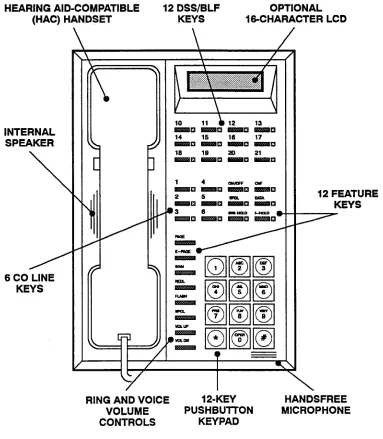
FIGURE 2-7. GLX-PLUS KEYSET
HEARING AID-COMPATIBLE 12 DSS/BLF OPTIONAL (HAC) HANDSET KEYS 16CHARACTER LCD
INTERNAL SPEAKER
\
6 CO LINE
KEYS
I \
, /
12 FEATURE KEYS
RING AND VOICE 1 P-KEY HANDSFREE VOLUME PUSHBUlTON MICROPHONE CONTROLS KEYPAD
INTER-TEL PRACTICES INSTALLATION GLX-PLUS INSTALIATION & MAINTENANCE Issue 2, June 1993
INSTALLATION
CONTENTS
PAGE
1. Introduction ...
2. System Installation Outline ...
3. Pre-Installation Checklist
...
A. Establish Suitable Environmental Conditions For The System ...
B. Assemble The Necessary Tools And Supplies ...
C. Plan Station Locations And Types Of Station Instruments
...
D. Assemble The Optional Equipment ...
4. Station Cabling And Terminations ...
A. Running Cable ...
B. Terminating The Cables At Station Locations ...
C. Terminating Station Cables At The Main Distribution Frame (MDF) ....
D. Station Loop Resistance Test ...
5. Terminating CO Lines At The MDF ...
A. CO Lines Terminated On RJ14 Jacks Near The MDF ...
B. CO Lines Terminated On RJ14 Jacks Away From The MDF
...
C. CO Lines Terminated On An RJ21X Block ...
6. KSU Installation
...
A. Unpack And Inspect The KSU ...
B. Install The Expansion PCB In The KSU ...
C. Install The Accessory Port Module (APM) In The KSU ...
D. Mount The KSU ...
E. Complete All Connections For The KSU ...
7. Station Installation ...
A. Keyset Installation ...
B. Single-Line Set Installation
...
8. External Paging Equipment Installation
...
9. External Music Source Installation ...
10.
Battery Back-Up Equipment ...
11. Post-Installation Checklist ...
3-2
3-2
3-4
3-4
3-4
3-5
3-5
3-6
3-6
3-7
3-8
I
3-11
3-12
3-12
3-12
3-14
3-15
3-15
3-16
3-16
3-18
3-21
3-22
3-22
3-31
3-31
3-31
3-33
INSTALLATION Issue 2, June 1993
INTER-TEL PRACTICES GLX-PLUS INSTALLATION % MAINTENANCE
1. INTRODUCTION
1.1 This section of the manual describes the recom- mended procedures for installing the GLX-Plus System hardware. Refer to the SPECIFICATIONS section of this manual for hardware descriptions.
2. SYSTEM INSTALLATION
OUTLINE
2.1 System installation is performed in the following order. Detailed instructions and figures for each step are
located throughout the INSTALLATION section.
(1)
(2j
(3)
(4)
(5)
(6)
(7)
Plan the installation, including the Key Service Unit (KSU) and main distribution frame (MDF) location, station locations, cable runs, and op- tional equipment. (Refer to the sample system layout shown in Figure 3-l on the next page.) Run station cables to the keysets and single-line sets. Run wiring to any optional equipment, such as the external paging network, external music source, etc.
Terminate the station cables on modular jack assemblies at the station locations.
Mount the MDF backboard, assemble the station block on the backboard, and connect the station cables to the station block.
Perform the station loop resistance test for each station cable.
If necessary, terminate the CO lines on modular jack assemblies at the MDF.
If necessary, attach the Expansion PCB or the Accessory Port Module (APM) to the KSU.
(8) Mount the KSU on the MDF backboard. (9) Ground the KSU.
(10) Connect the KSU to the cables and line cords
that
run from the MDF.
(11) Install the station instruments and any optional station equipment, such as headsets, handset am- plifiers, and Data Port Modules.
(12) Install any optional system equipment, such as external music source, external paging network, voice mail, answering machine, facsimile
machine, etc.
(13) Ensure that all equipment is working properly. (14) Refer to the PROGRAMMING section of this
manual to initialize and program the system.
NOTICE
INTER-TEL PRACTICES
GLX-PLUS INSTALLATION & MAINTENANCE Issue 2, June 1993 INSTALLATION
FIGURE 3-l.
SAMPLE SYSTEM LAYOUT
PAGING AMPLIFIER AND SPEAKERS D MUSIC
SOURCE MAIN DISTR~GUTION FRAME (MDF)
-- SURGE/SPIKE PROTECTOR
1
---cxG
AC-UNINTERRUPTED POWER SOURCEcl
g
ISOLATED DEDICATED AC OUTLET UP TO 12