Three-Phase Multi-LevelInverter for Grid Connected
System with Reduced Power Electronic Components
HARITHA INAVOLU Assistant Professor [email protected] Department of Electrical & Electronics
Engineering,
TKR Engineering College (Dt); Telangana, India.
K.V.DHANALAKSHMI Assistant Professor [email protected] Department of Electrical & Electronics
Engineering,
TKR Engineering College (Dt); Telangana, India.
ARCHANA.G Assistant professor [email protected]
Department of Electrical & Electronics Engineering,
TKR Engineering College, (Dt); Telangana, India
Abstract- This paper proposes symmetrical three-phase multi string seven-level inverter for various distributed energy resources DERs application. The simplified multilevel inverter requires only nine switches which reduces number of power devices and passive components, and control circuitry when compared to conventional cascaded H-bridge CCHB multilevel inverter. Three phase Cascaded H-Bridge Seven level inverter is interfaced with low frequency transformer with multiple PV Source is proposed. Nowadays multilevel inverter (MLI) plays a vital role in the field of power electronics and being widely used in many industrial and commercial applications. Moreover the advantages like high quality power output, low switching losses, low electro-magnetic interference (EMI) and high output voltage made multilevel inverter as a powerful solution in converter topology. The proposed topology has advantages like smaller filter size, and lower electromagnetic interference. Output harmonics are also reduced and hence total harmonic distortion is reduced. The proposed topology is implemented to grid connected system.Simulation results are shown for voltage and current during synchronization mode and power transferring mode to validate the methodology for grid connection.
Keywords—Three-phase multi-level inverter, low frequency modulation technique, symmetrical DC power sources, grid connected systems.
I. INTRODUCTION
Numerous industrial applications have begun to require higher power apparatus in recent years. Some medium voltage motor drives and utility applications require medium voltage and megawatt power level. For a medium voltage grid, it is troublesome to connect only one power semiconductor switch directly. As a result, a multilevel power converter structure has been introduced as an alternative in high power and medium voltage situations. A multilevel converter not only achieves high power ratings, but also enables the use of renewable energy sources. Renewable energy sources such as photovoltaic, wind, and fuel cells can be easily interfaced to a multilevel converter system for a high power application [1]. The concept of multilevel converters has been introduced since 1975 [2]. The term multilevel began with the three-level converter [3]. Subsequently, several
multilevel converter topologies have been developed [4]. However, the elementary concept of a multilevel converter to achieve higher power is to use a series of power semiconductor switches with several lower voltage dc sources to perform the power conversion by synthesizing a staircase voltage waveform. Capacitors, batteries, and renewable energy voltage sources can be used as the multiple dc voltage sources. The commutation of the power switches aggregate these multiple dc sources in order to achieve high voltage at the output; however, the rated voltage of the power semiconductor switches depends only upon the rating of the dc voltage sources to which they are connected [5].
of applied device voltage across seriesconnected devices that may make the applied voltage of individual devices much higher than blocking voltage of the devices during transient and steady-state switching operation of devices [9-10].
Grid-connected three-phase systems are nowadays recognized for their contribution to clean power generation. A primary goal of these systems is to increase the energy injected to the grid by keeping track of the maximum power point (MPP) of the panel, by reducing the switching frequency, and by providing high reliability [11]. In addition, the cost of the power converter is also becoming a decisive factor, as the price of the PV panels is being decreased [12]. This has given rise to a big diversity of innovative converter configurations for interfacing with the grid.
Fig.1.General Diagram of Proposed System.
II.THE PROPOSED MLI TOPOLOGY
A new multi-level three-phase voltage source inverter with reduced components count is introduced in this paper. Figure.2 (a) shows the generalized power circuit of the proposedtopology. It is for med through the arrange ment of the primary basic cell in series configuration that is shown in Fig.2(b). Every basic cell consists of three switches S1, S2, S3 and two symmetrical DC-power sources.
(a) Proposed topology.
Fig.2.The proposed MLI topology.
This cell produces three voltage levels as explained in the following: when S1 in ON state a 0 Vdc is produced on the cell terminal, when S2 in ON state a E Vdc is produced on the cell output, when S3 in ON state 2E Vdc is produced on the cell terminal ports. It should be noted that no switches could be operated in the ON at the same time in order to avoid a short circuit across the cell’s DC power sources. Table I summarizes the different switching states and the corresponding output voltage of the proposed MLI topology.
Table.I.Switching States for the Basic Cell
The proposed topology can be extended to have multi-levels more than three multi-levels per cell, by for ming a series configuration of the basic cell. The number of the generated output line voltage levels (M), output phase voltage levels (Mph), the number of the used basic cells (NCells), the number of switches (NSwitches) and DC power
supply (NSources) all are given in (1) - (5) respectively.
(1)
(2)
(3)
(4)
(5)
For exa mple to obtain a nine voltage levels on the output line voltage (Vab), according to the above equations, the investigated inverter produce five level per pole voltage (Vao), eleven voltage levels per phase (Van). Therefore, it is required for each arm to have two basic cells connected in series configuration, which is constructed from six switches and foursymmetrical DC-power sources. The proposed multi-levelinverter is recommended for the renewable energy resource especially the photovoltaic (PV) farms, at which there areenough DC energy sources to use.
In addition, the investigated topology is imple mented as symmetrical MLI. However, it can beimplemented as an asymmetry MLI, In this case, the voltage levels numberincreased dramatically as shown in Table .II. The relationship between the used DC-power sources voltages values will be: double ratio (D-Ratio) (E, 2E volt) or triple ratio (TR-ratio) (E, 3E volt). In this case, the equations controlled the number of the generated levels are matching the one presented in [12].
III. PROPOSED INVERTER SWITCHING SCHEME
Driving the inverter switches according to low frequency modulation, a square wave pulses have been generated
according to Table III. There are twelve modes of operation perone cycle (50 Hz). The driver signals for arm B and arm C are shifted by 120°, -120°, respectively. In order to produce three phase blanched output voltages, the MLI’s switching scheme that is shown in Fig.2 has to be accomplished. The switching devices for each ar m, fired by signals that are generated by Appling some logical operations on the six periods(P1 to P6). The six periods produced from the intersection of rectified sine wave with amplitude equal to (X volt), and a constant DC value equal to (X/2 volt), as shown in Fig.3. As the sine wave amplitude voltage (X) value varies, the switching signal width for each switch will vary also. Therefore, as a result the THD and the output voltage root mean square (Vr ms) will be varying. Equations (6) to (8) describe the logical operation applied on (P1 to P6) to produce the required switching devices signals (S1, S2, S3) for phase (A) as;
(6)
(7)
(8)
Where + stands for logic OR.
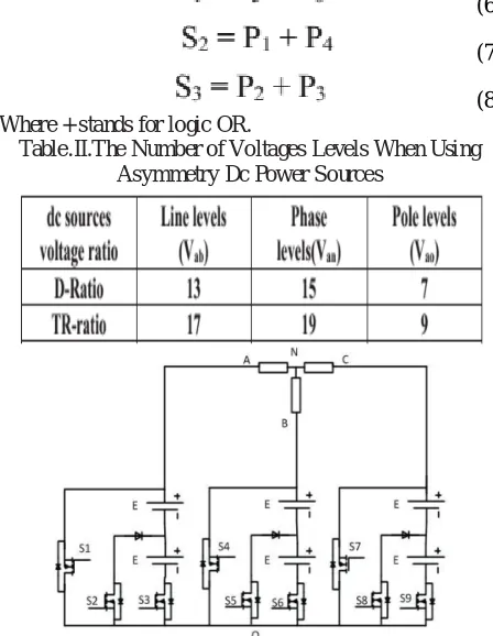
Table.II.The Number of Voltages Levels When Using Asymmetry Dc Power Sources
Fig.4.Proposed 3-level per pole / 7-level per phase MLI topology.
Table. IV.Comparison between Proposed Topology and other MLIs Topologies
IV.MATLAB/SIMULINK RESULTS
Fig.5.Matlab/Simulink model of three phase 7-level per phase MLI topology.
Fig.6.Switching scheme for S1, S2 and S3.
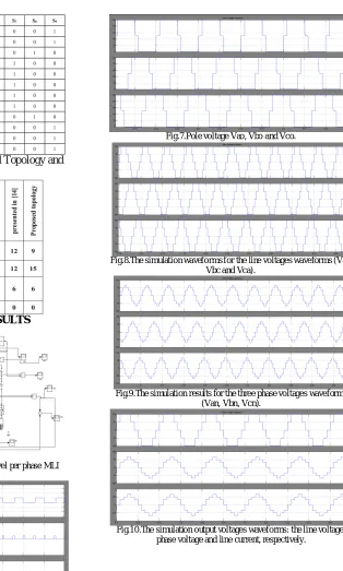
Fig.7.Pole voltage Vao, Vbo and Vco.
Fig.8.The simulation waveforms for the line voltages waveforms (Vab, Vbc and Vca).
Fig.9.The simulation results for the three phase voltages waveforms (Van, Vbn, Vcn).
Fig.11.Matlab/Simulink model of three phase 7-level per phase MLI topology with Grid Connected Systems.
Fig.12.Simulation wave form of the Gird voltage and current.
V.CONCLUSION
Three-phase multi-level inverter topology is proposed in this paper. The proposed inverter has the advantages of reducing the number of switches and gate drives circuits by 25 % compared with the conventional Multi-level inverter. Therefore, the proposed inverter exhibits the merits of simplified gate drive, high efficiency, low cost compared to the othertopologies for the same number of phase voltages levels.Multilevel inverters offer improved output waveforms and lower THD. This paper has presented switching scheme for the proposed multilevel inverter. The behavior of the proposed multilevel inverter was analyzed in detail. By controlling the modulation index, the desired number of levels of the inverter’s output voltage can be achieved. The less THD in the seven-level inverter compared with that in the five- and three-level inverters is an attractive solution for grid-connected inverters.
REFERENCES
[1] Hammond, P.W, “A new approach to enhance power quality for medium voltage AC drives,” IEEE Trans. Ind. Appl., 1997, 33, (1), pp. 202–208
[2] S. J. Park, F. S. Kang, M. H. Lee, and C. U. Kim, “A new single-phase five level PWM inverter employing a deadbeat control scheme,” IEEE Trans.Power Electron., vol. 18, no. 18, pp. 831–843, May 2003. [3] Agelidis, V. G., Baker, D. M., Lawrance, W. B., and Nayar, C. V.,“A multilevel PWM inverter topology for photovoltaic applications,”
Proceedings of the IEEE International symposium on Industrial Electronics, Vol. 2, pp. 589-594, July 1997, Portugal, Guimaraes. [4] Gui-Jia Su, “Multilevel DC-Link Inverter”, IEEE TRANS.IND. APPLICATIONS, vol. 41, no. 3, may/june 2005.
[5] M. Calais, L. J. Borle, and V. G. Agelidis, “Analysis of multicarrier PWM methods for a single-phase five-level inverter,” in Proc. 32nd Annu. IEEE PESC, Jun. 17–21, 2001, vol. 3, pp. 1173–1178.
[6] Abdelaziz Fri, Rachid El Bachtiri, Abdelaziz El Ghzizal, “Basic topologies of a three-phase inverter (5l) for a photovoltaic system controlled by multi-carrier spwm,” Journal of Theoretical and Applied Information Technology, 10th september 2013. vol. 55 no.1
[7] A. Nabae, I. Takahashi, and H. Akagi, “A new neutral-point clamped PWM inverter,” IEEE Trans. Ind. Appl., vol. 1A-17, no. 5, pp. 518-523, [8] M. F. Escalante, J. C. Vannier, and A. Arzande, “Flying capacitor multilevel inverters and DTC motor drive applications,” IEEE Trans. Ind.Electron., vol. 49, no. 4, pp. 809–815, Aug. 2002.
[9] M. Malinowski, K. Gopa kumar, J. Rodriguez, M. Pérez., “A Survey on Cascaded Multi-level Inverters,” IEEE Trans Ind. Electron., vol. 57,no.7, pp. 2197-2206, 2010.
[10] S. Nagaraja Rao , D.V. Ashok Kumar, Ch. Sai Babu, “Ne w Multilevel Inverter Topology with reduced number of Switches using Advanced ModulationStrategies,” 2013 International Conference on Power, Energy and Control (ICPEC).