Optimization and Control of Boiler in Pulp
and Paper Industry
B.Karthik1, V.Pushparajesh2
PG Scholar, Department of EEE, Kongu Engineering College, Perundurai, Tamilnadu, India 1
Assistant Professor, Department of EEE, Kongu Engineering College, Perundurai, Tamilnadu, India 2
ABSTRACT
:
A boiler–turbine unit is a configuration that is widely used in modern power plants. The basic purpose of any boiler is to convert the chemical energy in fuel into thermal energy that can be used to generate steam or hot water.First, the fuel must be mixed with sufficient oxygen to allow sustained combustion. During the combustion process, oxygen, carbon and hydrogen are reacted, and other elements in the fuel to produce a flame and hot combustion gases. The heated gases produced by the combustion process must then transfer the thermal energy to a fluid such as water or steam, by using this turbine is operated and the power is generated. Combustion boilers are designed to use the chemical energy in fuel to raise the energy content of water so that it can be used for heating and power applications. The most common types of fuel include coal, oil, and natural gas. Most boilers are classified as either water tube or fire tube boilers. The configuration uses a single water tube boiler to generate steam and directly feed the steam to a single turbine to generate electricity.In this project, a nonlinear unit model is proposed. The model is built for subcritical units with pulverized-coal-fired, naturally circulated drum boilers. The reduced model of the boiler has been developed by using the mill dynamic equation, equation for pressure drop between drum and boiler, energy balance equation for boiler, and the energy balance equation for turbine. The main objective is to control the power output from the power plant. The power level is controlled by varying the ratio of air and coal that are given to the combustion chamber with respect to the main steam from the boiler. Several conventional PID controllers and Genetic Algorithm based PID controller are developed to control the power level of the plant. The comparison of these controllers based on several performance indices are made to find the best method to control the power level of the boiler.
KEYWORDS: Boiler control, Optimization, Conventional tuning methods, Genetic algorithm, PID
I. INTRODUCTION
Fig. 1 Diagram of boiler turbine unit
Abdennour AB[1] et al discuss about the boiler system ,is a MIMO system with the characteristics of nonlinear dynamics, with there being severe loading variation, the boiler variables such as steam pressure and water level undergo some major fluctuations.This paper contributes a methodology to design a two-level structure control method to improve the performance of the boiler response.Dimeo R[4] et al discuss about the application of a genetic algorithm to control system design for boiler-turbine plant.Y. J. Cao & Q. H.[6] Wu discussed about an attractive approach for teaching genetic algorithm (GA) is presented. This approach is based primarily on using MATLAB in implementing the genetic operators: crossover, mutation and selection and it is analyzed to find global or near-global optimum solutions of multi-modal functions.WenTan,Fang[11] et al analyzes the nonlinearity of the unit and selects the appropriate operating points so that the linear controller can achieve wide-range performance.
II. MODELLING OF THE BOILER
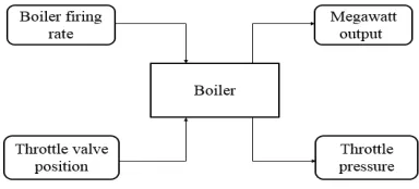
A reduced model of a boiler is derived based on the two input parameters, Master air controller and coal controller and the output main stream controller. The throttle value position and the boiler fairing rate are the two inputs given to the boiler and these input parameters are to be varied. Accordingly the MW output and throttle pressure changes. Thus, these parameters need to be calibrated for each particular plant. The block diagram of the boiler model is shown in Figure 2.1.
Figure 2.1 Block diagram of the model
Detailed models on boiler-turbine units are rare in the open literature, to describe the Nonlinear modelling equatation of boiler, there are four major parameters are to be considered
Pressure drop between drum
And Throttle pressure : = − ( ). (2.4)
Where B , µ, PT , N , and PD are five variables and K1 , K2 , K3 , τ , K f , C B ,Kt are seven parameters and all the symbols are described in Table 3.1.2
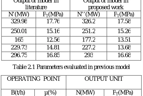
The comparison of inputs and outputs of the model from the literature survey is given in Table 2.1. The proposed
model analysis are displayed in Table 2.2. The error between the literature and proposed model are obtained in Table 2.3 Error comparison of above two model
Table 2.1 Parameters evaluated in previous model
Table 2.2 Parameters evaluated in proposed model
Table 2.3 Error comparison of above two model Output of model in
literature
Output of model in proposed work N’(MW) PT(MPa) N’’(MW) PT(MPa)
329.98 17.76 326.2 17.58
250.01 15.16 251.2 15.26
165 12.56 177.2 13.51
229.73 14.81 227.2 13.68
296.75 16.85 293 16.68
OPERATING POINT OUTPUT UNIT
B(t/h) µ(%) N(MW) PT(MPa)
52.27 79.60 328.86 17.61
40.26 70.66 248.16 15.29
28.40 56.29 168.58 12.38
34.00 66.58 227.3 14.69
46.96 75.37 295.56 16.79
Error in literature Error in proposed method (N’-N)/N (PT ‘-PT)/PT
(N’’-N)/N
(PT”-PT)/PT
0.3 0.9 0.08 0.02
0.3 -0.9 0.08 -0.02
-2.0 1.5 0.5 0.9
1.1 0.8 -0.6 -0.6
Table 2.4 Values of the dependent variables at Dilate Power
III. CONVENTIONAL PID CONTROLLER
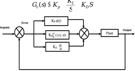
PID controllers are the most widely-used type of controller for industrial applications. They are structurally simple and exhibit robust performance over a wide range of operating conditions. In the absence of the complete knowledge of the process these types of controllers are the most efficient of choices. The three main factors involved are Proportional (P), Integral (I) and Derivative (D). The proportional part is responsible for following the desired set-point, while the integral and derivative part account for the accumulation of past errors and the rate of change of error respectively. The basic block diagram of PID controller is shown in Figure 4.1.The structure of the PID controller is as follows:
(3.1)
Fig. 3 Block diagram of a conventional PID controller
The best response can be achieved by proper tuning of KP, KI and KD values of PID controller. The boiler is controlled
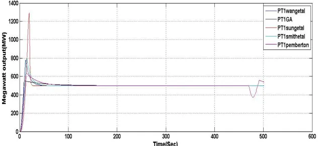
by using the conventional tuning rules such as standard form optimization minimum ITAE Sung, standard form optimization Smith, standard form optimization Wang, standard form optimization Pemberton. The tuning rules for standard form optimization minimum Sung, standard form optimization Smith, standard form optimization Wang, standard form optimization pemberton are shown in Table 4.1
Table 3 Tuning Rules of Standard Form Optimization Minimum ITAE Sung, Standard Form Optimization Smith, Standard Form Optimization Wang, Standard Form Optimization Pemberton
Parameters Values
K1 6.313
K2 0.000138
K3 0.2334
PD 18.59
Kt 16
C B 2100
Τ 60
K f 145
S
K
S
K
K
s
G
I Dp
Where,
Fig.4 Flow Chart of Genetic Algorithm Based PID Controller
The most challenging part of creating a genetic algorithm is writing the objective functions. In this project, the objective function is required to evaluate the best PID controller for the system. An objective function could be created to find a PID controller that gives the smallest overshoot, fastest rise time or quickest settling time. However in order to combine all of these objectives an objective function is designed to minimize the performance indices of the controlled system instead. The binary coded genetic algorithm is a probabilistic search algorithm that iteratively transforms a set (called a population) of mathematical objects (typically fixed-length binary character strings), each with an associated fitness value, into a new population of offspring objects using the Darwinian principle of natural selection and using operations that are patterned after naturally occurring genetic operations, such as crossover and mutation.
Conventional PID control: Based on the order of boiler modelling equation, tuning of PID controller has been done by using four tuning rules.
Standard form optimization –minimum ITAE-Sung Standard form optimization –Wang
Standard form optimization –Pemberton Standard form optimization –Smith
Table.4 Tuning Parameters of PID Controller
IV. CONCLUSION
The reduced model of the boiler has been developed by using the mill dynamic equation, Equation for pressure drop between drum and boiler, Energy balance equation for boiler, and the energy balance equation for turbine. The simulated model has been validated against the code that are used in the industry. Manual tuning of PID controller and Conventional PID controller are used to control the boiler. A genetic algorithm based PID controller has been implemented for controlling the boiler by manipulating the air and coal at exact ratio, the amount of main stream controller is controlled, and from this the required power for the plant will be obtained.From the results, it is clear that the Genetic Algorithm based PID controller (GAPID) shows satisfactory performance when compared to other controllers for the boiler
REFERENCES
1. A.B Abdennour ,“An intelligent supervisory system for drum type boilers during severe disturbance”, Electrical Power and Engergy Systems 2000;22:381–7.
2. KJ Astrom and K Eklund. “A simplified non-linear model of a drum boiler–turbine unit”,International Journal of Control 1972;16(1):145–69.
3. RD Bell and KJ Astrom, “Dynamic models for boiler–turbine-alternator units: data logs and parameter estimation for a 160 MW unit”, report LUTFD2/(TFRT-3192)/1-137. Lund (Sweden): Dept. of Automatic Control, Lund Institute of Technology. 1987.
4. Y. J Cao. and Q. H. Wu, 1999, Teaching Genetic Algorithm Using MATLAB Int. J. Elect. Enging. Educ., Vol. 36, pp. 139–153.
5. E. Cheres, “Small and medium size drum boiler models suitable for long term dynamic response”,IEEE Transactions on Energy Conversion 1990;5(4):686–92.
6. R Dimeo, K.Y Lee, “Boiler–turbine control system design using a genetic algorithm”, IEEE Transactions on Energy Conversion 1995;10(4):752–9.
7. F.Fang, J.Z Liu, W. Tan , “ Nonlinear internal model control for boiler–turbine coordinated systems of power unit”, Proceedings of the CSEE 2004;24(4):195–9
8. J.A Rossiter, B Kouvaritakis, R.M. Dunnett, “ Application of generalized predicative control to a boiler–turbine unit for electricity generation”, IEE Proceedings — Control Theory and Applications 1991;138(1):59–67.
9. W Tan, J.Z Liu, F Fang, Y.Q Chen, “Tuning of PID controllers for boiler–turbine units”, ISA Transactions 2004;43(4):571–83.
10. L Tian , D.L Zeng , J.Z Liu , Z. Zhao, “ Simplified nonlinear dynamic model for a 330 MW unit”,Proceedings of the CSEE 2004;24(8):180–4 [in chinese].
11. Wen Tan, Fang Fang, Liang Tian, Caifen Fu, Jizhen Liu, “ Linear control of a boiler–turbine unit: Analysis and design. Department of Automation and Key Laboratory of Condition Monitoring and Control for Power Plant Equipment (Ministry of Education)”, North China Electric Power University, Zhuxinzhuang, Dewai, Beijing, 102206, China
TUNING RULES KP KI KD
Standard Form Optimization Minimum ITAE Sung 1.7 1.5 0.125
Standard Form Optimization Smith 8 1 0.001
Standard Form Optimization Wang 0.6 0.8 0.001
Standard Form Optimization Pemberton 9 0.4 0.001