Helgol~inder wiss. Meeresunters. 20, 278-292 (1970)
Preliminary experiments with Bryozoa in a simple
apparatus for producing continuous water currents
D . JEBRAM
Zoologisches Institut, Universit~it KieI; KieI, Germany (FRG)
KURZFASSUNG: Erste Experimente mit Bryozoen in einem einfachen Apparat zur Erzeu- gung kontlnuierlicher Wasserstr6mungen. Ein neuer, einfacher Apparat fLir Experlmente mlt Wasserstr6mungen wird beschrieben. Der Apparat wurde so konstruiert, daf~ die im Wasser suspendierten planktischen Futterorganismen bei der Erzeugung der Wasserstr6mung m~Sglichst nicht gesch~idigt werden. Die Wasserstr6mung wird durch einen effektiven Typ einer Blasen- pumpe erzeugt. Ihre Geschwindigkeit ist regulierbar und kann ein Maximum yon ungef~hr 1/2 m/sec erreichen. Der Apparat kann zu Experimenten mit kleinen Tieren und Pflanzen be- nutzt werden, insbesondere mit sessilen und hemisessilen Formen. Es werden einige Experimente mit Bryozoen in diesem Apparat beschrieben. Electra monostachys und E. piIosa zeigen eine positiv rheotropische Wuchsreaktion in niedriger Str~Smungsgeschwindigkeit. E. pilosa scheint durch WasserstrSmung zur Bildung aufrechter Kolonlenteile stimuliert zu werden. Die M~Sg- lichkeit des Einflusses yon Wasserstr~Smungen auf den Wuchs der forma-erecta-B~lle yon E. pilosa wird diskutiert.
I N T R O D U C T I O N
The colony forms of some Bryozoan species suggest that their growth is affected by water movement. It is not practicable for growth studies to employ an agitation machine (HAvENSCHILD 1962, SCHLIEVER 1968) for producing water movements, be- cause the resulting turbulence is difficult to control and its effects on the test animals are too difficult to analyse. For creating simple, continuous water currents an appa- ratus is necessary which satisfies the following requirements: (1) Avoidance of detri- mental effects in regard to the planktonic food suspended in the water; (2) regulation of the water currents from very slow to very high speeds; (3) the apparatus must be easy to use, to clean and, in certain cases, to be sterilized; (4) the components of the apparatus must resist corrosion and chemical effects.
Experiments with Bryozoa 279
It was, therefore, necessary to develop a new apparatus for the above-mentioned requirements.
RESULTS
D e s c r i p t i o n o f t h e n e w a p p a r a t u s
Raising water by air bubbles
In order to avoid damaging the planktonic food organisms, I have chosen air bubbles to li~ water above the level in the experimental vessel. The water falls from the higher level through a jet-tube into the experimental vessel, where it drives the water into a circular movement. The principle of lit~ing water via air bubbles in an ascending tube is a well known simple technique
(NEEDHAM
1959, HUCKSTEDT 1963, KRi)GER 1966, GREVE 1968, SCHLIEPER 1968).In an attempt to make this method more effective, B(SCKLE* some years ago developed a "bubble-pump" in the Zoologisches Institut (University of Kiel). In this
R
Fig. 1: "B/3c~Lr-pump" atter a sketch of Dr. R. BENESCH, Erlangen. Abbreviations see Figure 2
pump air is retained by a bubble-cup and thus concentrated into larger bubbles with larger water carrying capacity (Fig. 1). B0CKLE'S construction, however, was not adequate for m y purposes. I have, therefore, designed another type of bubble-pump (Fig. 2) made of glass.
The apparatus creating water currents
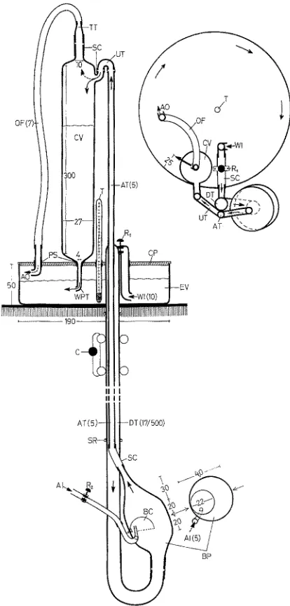
The apparatus, seen from front and above, is illustrated in Figure 2. It consists of three main parts: e x p e r i m e n t a l v e s s e l , b u b b l e - p u m p , and c o n - t a i n e r v e s s e 1 ; all three parts are connected to each other by tubes.
A w a t e r - i n l e t - t u b e sucks water from the experimental vessel. It is connected with the horizontal upper part of the d e s c e n d i n g t u b e by a piece
280 D. JEBRAM
of silicon-rubber tube. The bubble-pump is connected through its bottom inlet opening with the U-part of the descending tube below. The bubble-pump consists of a body which is tapered at its top. The b u b b 1 e - c u p is fixed at the back in the middle of
T
I l l l
I l l l
Fig. 2" Water current producing apparatus (seen from the front and from above). AI air inlet, AO air outlet, AT ascending tube, BC bubble-cup, BP bubble-pump, C clamp, CP coverplate, CV container vessel, DT descending tube, EV experimental vessel, OF overflow tube, PS packing sleeve, R1 regulation of WI, R2 regulation of AI, SC silicon-rubber connecting tube, SR rubber securing ring, T thermometer, TT tapered tube, UT U-tube, WI water-inlet-tube,
Experiments with Bryozoa 281
the body with the opening downwards, inclining upwards from the point of fixation. A c a p i 11 a r y t u b e projects from below into the bubble-cup; it brings in air from the aeration pump. The bubble-pump is connected at the top with the a s c e n d i n g t u b e, which enters the container vessel through a U-tube. From the container vessel a w a t e r - p r o p e l l i n g - t u b e leads downwards through the c o v e r p l a t e into the experimental vessel. An o v e r f 1 o w - t u b e, connected with a glass tube, also leads from the top of the container vessel through the coverplate into the experi- mental vessel.
The circular shape of the experimental vessel was chosen to reduce water friction. In such a circular vessel relatively high current speeds can be created with relatively low energy expenditure.
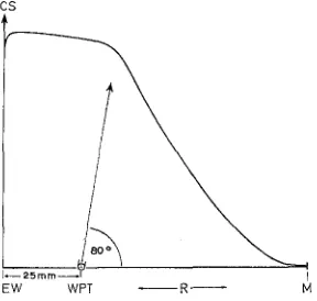
Tests have shown that the water-propelling-tube should be placed 20 to 25 mm from the external wall of the experimental vessel. The most effective direction for the outflow of water from the water-propelling-tube has been found to be at an angle of about 80 o to the radius of the experimental vessel (Fig. 3).
Materials used in the apparatus
Experimental vessel, descending tube, bubble-pump, ascending tube, and con- tainer vessel are of glass. The connecting tubes are of silicone rubber. The packing sleeves in the coverplate and the overflow-tube are also of silicone rubber. The cover- plate is plexiglass to facilitate the drilling of holes. Glass, plexiglass, and silicone rubber are chemically relatively inert to seawater, easily cleaned and may be sterilized in temperatures of up to 110 ° C.
Functioning of the apparatus
The water in the experimental vessel is forced into circular movement by water which flows horizontally out of the water-propelling-tube aRer falling from the con- tainer vessel. The speed of the resulting water current is a function of the amount of water entering per unit time and the total amount of water contained in the experi- mental vessel. The amount of inflowing water is regulated by the diameter of the opening of the water-propelling-tube and by the height of the water in the container vessel above the experimental vessel. The diameter of the opening of the water-pro- pelling-tube should be adjusted to the water output of the bubble-pump and should not be too large; otherwise the water runs out of the container vessel too quickly when a sufficient height of water cannot be attained. Then the hydrostatic pressure would be insufficient to force the water out of the water-propelling-tube rapidly enough. The height of the water level in the container vessel depends on the water output of the bubble-pump, which is a function of several factors:
282 D.J~BRAM
also on the surface-tension of the seawater. Therefore, it is impossible to make the bubbles as large as desired. This explains the main limit for the efficiency of the bubble- pump. The diameter of the ascending tube should be adjusted to the size and carrying capacity of the air bubbles.
(b) The bubble-pump's capacity for work depends moreover on the speed of the water inflow. The inflow speed is affected by gravity and by the descending tube height. The water level in the experimental vessel is too low to produce the necessary hydro- static pressure for a fast inflow into the bubble-pump (NE~DHAM 1958, KRi).G~R 1966). Therefore, the bubble-pump hangs underneath a 50 cm descending tube, which should be a little thicker than the ascending tube. The descending tube, however, should not be too large, otherwise too much water would flow into the bubble-pump, and the carry- ing capacity of the bubbles would not suffice to carry the large portions of water.
In regard to the experimental vessel, water height and diameter should not be too large, lest the experimental vessel contains too much water, so that too large a quantity of water inflowing would be needed for sustaining the water current required. Hence the dimensions of the experimental vessel are conveniently limited. If desired, one may, however, overcome these limitations by using more than one bubble-pump for each experimental vessel. Thus larger experimental vessels may be used, or higher current speeds produced in smaller vessels.
Current gradient in the experimental vessel
The circular movement of the water causes current gradients (Fig. 3). The current speed attains maximum values along the external vessel wall. Some centimeters from
CS
/
J ~ 2 5 r n m ~ l
EW WPT R
Fig. 3: Distribution of the current speed in the experimental vessel. CS current speed, EW external wall, M centre, and R radius of the experimental vessel, WPT water-propelling-tube.
The arrow indicates the direction of the water outflow
Experiments with Bryozoa 283
Use of the apparatus
Regulation of current speed
There are two means of regulating the current speed with one pumpset, by varying the height of the water level in the container vessel:
(a) Regulation of air input with R2 (Fig. 2). Air bubbles input, however, cannot be accelerated as much as desired. If the air input is increased too much no large bubbles will be formed, but many small irregular ones. Then the air pressure in the bubble- pump is greater than the hydrostatic pressure of the water, and no water wilt be raised. (b) Regulation of water inflow with R1 (Fig. 2) through the descending tube into the bubble-pump. The potential range of current speed variation by varying water inflow is considerably greater than by varying air input. Therefore, R1 represents the main current speed regulator. Water inflow is limited due to size and speed of air bubbles. If the water inflow increases too much the water portions between successive bubbles become too heavy and cannot be li~ed.
In the range of low current speeds (less than about I5 cm/sec) smaller dimensions in the pumping set should be used (as indicated in Figure 2) in order to facilitate better regulation. (Descending tube 13 mm, bubble-pump 22 mm, bubble-cup 10 mm ~Y, con- tainer vessel height 150 mm.)
Applications for the apparatus
The apparatus may be useful for testing the effects of two aspects of water move- ment (RIEDL 1964, 1966): (1) Speed of water particles (cm/sec); important for pro- blems of current exposure, rheotaxis and rheotropism. (2) Current volume, rate of change of water (ml/cm2); important for the provision of adequate food for filter feeders, for problems of gas exchange in respiration, and ion exchange through the epidermis.
The apparatus was designed mainly for the possibility of utilization of planktonic food organisms in experiments with water currents. Only planktonic food organisms with high mobility are suitable for use in this apparatus, especially during higher current speeds. I was successful in my current experiments with Bryozoa fed with
Oxyrrhis marina. DunaIieIla
sp. was used to feed O.marina,
a heterotroph Dino-flagellate (JEBI~A~ 1968b).
Cryptomonas
sp. represents in many cases good food for Bryozoa but because it is not a sufficiently active swimmer, it has proved unsuitable in this apparatus.Cryptomonas
sp. o~en sinks to the bottom and is washed into the cor- ners of the experimental vessel, where it remains and hence cannot be eaten by the experimental animals.284 D. JEBRAM
tests with vagile and hemisessile species with respect to their preference to current speeds, e.g. Polychaeta, Mollusca, Crustacea. The apparatus is also suitable for current experiments with small sessile algae.
S * /
. - r
4.-'-'--5
J P h
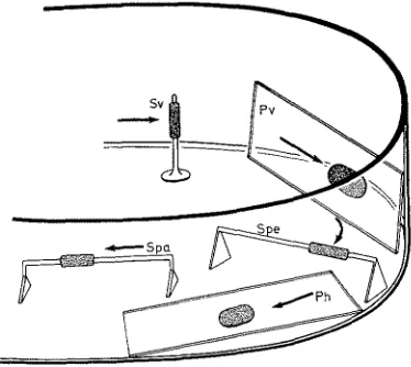
Fig. 4: Placing of sessile organisms under different conditions of water current exposure (in relation to gravity and light from above). Ph horizontal plate (glass slide), Pv vertical plate, Spa glass rod parallel to the water current, Spe glass rod perpendicular to the water current,
Sv vertical glass rod; experimental organisms are indicated by dotted areas
E x p e r i m e n t s w i t h B r y o z o a
Several species of Bryozoa were reared at different water current speeds under conditions of dim light, 30 (+_ 0.5) %0 S, 15 (+_ 1) 0 C. The Bryozoa grew on glass slides or coverslips (J~BRA~ 1968b) placed vertically in the maximum speed near the external wall of the experimental vessel (Pv, Fig. 4). The speeds of the water current were calculated from the measured circulation times of small particles. The Bryozoa were fed with Oxyrrhis marina.
Farrella repens (FA~RE)
One slide with several small colonies was exposed to a speed of about 15 cm/sec for five weeks (Fig. 5, A-B). Another slide with one small colony was exposed to a current speed of about 3 cm/sec (Fig. 5, C-D). In both experiments the colonies grew nearly equally well in all directions, irrespective of the water current direction. The stolons continued to grow in most cases in the original direction without regard to the current direction except when they met an obstruction.
Experiments with Bryozoa 285
conditions, no preferred growth direction relative to the current direction could be observed. N o explanation can, at present, be offered to account for the different results. Perhaps the temperature during the experiment influences growth; MARCUS probably experimented at higher temperatures (19.50-21 ° C) than I. The different food sources (native food versus artificial monofood) may have also influenced the growth. Whether the small difference in the current speed (1 versus 3 cm/sec) may have been of significance remains unsettled. G r o w t h and maturation of many zooids during the ex- periments indicated that the experimental conditions were not unfavourable.
A) 27, 5.59
"7"
i ... i lcm
B) 5.7.69
b ~J
c) 5. 7. ~9 7 D) 21.7. 69
b b
Fig. 5: Farrella repens (FAI~RE). Development of colonies exposed to current speeds of 15 and 3 cm/sec; b border of glass slide. The dotted area in B is densely populated with zooids
lCm
Fig. 6: Farrella repens (FARRU). Growth of long stolons with few zooids in still water in 15 0 C during 10 days; b border of glass slide, f fixation thread, sc central colony from which the
stolons started to grow
286 D.
JEBRAM
Conopeurn seurati (CANu)
Two colonies were exposed to a speed of about 15 cm/sec for some weeks (Fig. 7, A-B). The colonies showed no preferred growth direction relative to the direction of the water current.
A) 10.2.69 B) 27.5.69
-15 cm/sec
I~ :...~..,~
b
Fig. 7: Conopeurn seurati (CANt 0. Development of a colony in steady water currents; b border of glass slide, arrows indicate the main growth directions
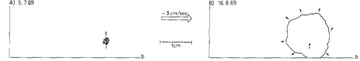
A) 5 7 6 9 B) 16.869
t
i r l'crm
b
f
Fig. 8: Conopeum reticulum (L.). Development of a colony in steady water currents; b border of glass slide, arrows indicate the main growth directions
Conopeum reticulurn (L.)
One colony was exposed to a speed of about 3 cm/sec (Fig. 8, A-B). The growth of the colony against current direction was not essentially more intense than the colony expansion in current direction (72/3 m m : 61/3 mm).
Water currents seem to have no important influence on the colony form in Cono- peum seurati and C. reticulum. This compares favourably with the nearly circular out- line of larger colonies on plane substrate in native waters. In the laboratory both indigenous Conopeum species normally grow more or less symmetrically in all direc- tions in still water as well as in slow turbulent currents and in slow or fast steady water movements.
Electra monostachys (BusK)
Experiments with Bryozoa 287 of them turned back against the direction of the water current. (The larger colonies became mature during the current experiments.)
Under natural conditions this species builds, in most cases, a serial arrangement of zooids, but sometimes sheet-like colonies also (J~m~i~ 1968a) (Fig. 10). Therefore, the observation seems to be important, that Electra rnonostachys maintained in the labora- tory at higher water current speeds show a tendency to form rather dense, plate-like
A) 27.5,69 B) 5.7,69
- 15 cmlsec
lcm
b
C) 13.7.69 D) 29,8,69 E) 21.769 F) 29.8.69
e'
- 3 cm/sec
, 5
P ~
Icm
~ 3 cm/sec
Fig. 9: Electra monostachys (BusK). Development of colonies exposed to water currents of 15 and 3 cm/sec. In the centre of B a crowded arrangement of the zooids is shown by irregular growth of new zooids over the older ones. In D the presence of several zooids series has pro- duced small turbulences, which stimulate some of the series to grow in the same direction as the main water currents, contrary to the positive rheotropic growth of most of the zooid
series; b border of coverslip
colonies without a preferred growth direction relative to the current direction. In slow currents or stagnant water, serial arrangements of zooids dominate. E. rnono- stachys shows a distinct positive rheotropic growth reaction in slow current speeds only.
I have observed that Electra rnonostachys lives in the southern part of the N o r t h Sea on shells of lamellibranchs, especially on estuarine shell beds and near the Fri- sian Islands (JeBI~AM 1969). In these environments strong currents and turbulences, interrupted by periods of nearly still water, dominate. The shells serving as substrate for the Bryozoa alter their position very otten, so that the Bryozoa become exposed to water currents of changing directions and speeds.
Electra pilosa (L.)
288 D. JEBRAM
rent. Two zooids rose from the substrate (arrows in Fig. t l , B), as though beginning to build erect colony parts. Unfortunately, the proximal p a r t of the colony died from a defect in the food, so that the experiment had to be discontinued.
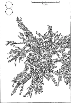
Fig. I0: Electra rnonostachys (BusK). Arrangement of zooids in water moved very slowly and irregularly, as indicated by the dotted, circular arrows. This arrangement closely resembles the
colony form in situ
A) B)
b ~ . . .
.. 5 cm/sec . . . , ~ - ~
C) 28.669 D) 9.8.69 I
5 cm/sec
L 5
_ . ~ _ _ b
Fig. 11: Electra pitosa (L.). Development of coIonies in sIow current speeds (in D the distal zooids on the lett side are grown in 15 cm/sec). The arrows in B and the bla& mark in D
indicate initial stages of E. pilosa forma erecta; b border of coverslip
Experiments with Bryozoa 289
the current direction. Then the colonies were exposed to a speed of about 15 cm/sec for about two weeks. Under the influence of this higher current speed the colonies showed no special reaction: the buds grew straight ahead in the same direction as at the be- ginning of the higher speed (Fig. 11, D, distal colony parts on lett side). In this experi- ment also the growth of a forma-erecta-branch started: a~er contact one zooid of each colony began to grow upwards from the substrate, the zooids using each other as a base, and producing distal buds (black point in Fig. 11, D).
In Electra pilosa as well as in E. monostachys, in m a n y cases the series of zooids which grew strictly in the same direction as the current direction continued this growth direction.
1cm
//'
[Fig. 12: Electra pilosa (L.). Arrangement of the zooids in a young colony with the typical star-like form on a piece of Larninaria sp. A ancestrula; arrows indicate lateral budding;
black areas are not covered by zooids
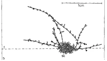
In nature, on a flat undisturbed substratum, Electra pilosa builds colonies in the form of elongated stars (MAt~cus 1926) resulting in an intermediate form between a plate-like colony and a serial arrangement of the zooids (Fig. 12).
Both of m y experiments show a clearly positive rheotropic growth reaction under the influence of slow water current speeds. Moreover, in both experiments, initial stages of erect colony parts were formed. I have not observed the growth of such structures typical of E. pilosa forma erecta in colonies of Electra pilosa in still water in the laboratory. The observed degree of initial formation of erect colony portions during the current experiments was indeed small, but, considering that E. pilosa is still difficult to cultivate under totally artificial conditions, this response seems to be of special interest.
290 D. JEBRAM
E. pilosa forma erecta occurs sometimes in extremely large masses and can become a nuisance for fishermen and tourists (Gl~ooT 1965, FEYFER-TEuTELINK 1965, M/~LLER 1966, PRIGCE 1967). PRIGG~ (1967) searched for the causes of the formation of the ball- form of E. pilosa forma erecta, but could not offer an explanation, except that he con- firmed suggestions made by earlier observers, namely, that the ball-form must have originated from pieces of normal E. pilosa forma erecta torn loose from the substrate. The positive rheotropic growth reaction of Electra pilosa and the stimulation of the formation of the forma erecta by slow water currents suggests that the ball-form - in contrast to PRIGGE'S (1967) assumption - and the forma erecta develop in moving but not in still waters (only settling of Cyphonautes larvae probably requires still water). While diving near Helgoland I found colonies of E. pilosa forma erecta ad- hering to their substrate which approached the ball-form. In the southern part of the North Sea and in the Oosterschelde (Netherlands) I found all possible intermediate stages between the normal forma erecta and the ball-form floating in the water.
I ]I ~I ff
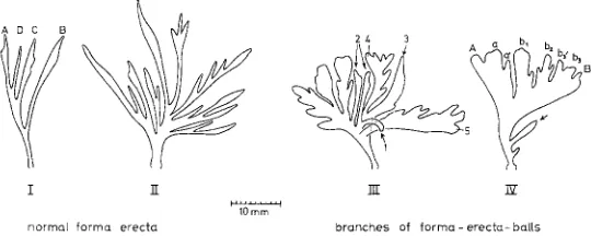
normQ[ forma erecta branches of f o r m a - erects- halts
Fig. 13" Electra pilosa (L.) forma erecta. Types of branches; the letters indicate the pattern of branching; the figures on branch III indicate different stages of the development of se- condary and tertiary side branches from simple, narrow forms (arrows) to larger ones with side branches; all branches are projected from their three-dimensional arrangement into one
plane
Experiments with Bryozoa 291
only will be formed (Fig. 13, I I I , 3-5). With different intensities of habitat water movement one finds all possible intermediates between branch-forms I to I V (Fig. 13). Water movement is surely not the only, but probably an important factor in the development of the ball-form of E. pilosa forma erecta. Other factors of importance are presumably: (1) salinity (I have not yet found the typical forma erecta in the southwestern part of the Baltic Sea), (2) temperature, and (3) food (sufficient quantity and suitable quality for rapid growth of the masses of ball-colonies).
G e n e r a l c o n c l u s i o n s
The tested bryozoans showed either no rheotropic growth response or a positive rheotropic growth response only at slow water current speeds. In fast currents the bryozoans do not grow in a preferred direction relative to current direction. Perhaps all buds around the colony are affected with nearly the same strong intensity by fast current speeds. Slow water currents probably act as growth stimuli while strong water currents retard growth through excessive stiraulation.
In fast currents stolonial and serial forms tend to cover the occupied substrate area densely with zooids. When water currents become too fast evagination of polypids is prevented, thereby causing malnutrition and reduced growth of new zooids.
S U M M A R Y
1. An improved type of bubble-pump and an apparatus for producing continuous water currents, designed especially for utilization of planktonic food, are described. 2. The operation of the apparatus is easy; current speeds can be regulated from 0 to
about t/2 m/sec.
3. The apparatus can be used for experiments on small animals and plants, especially sessile and hemisessile forms.
4. Bryozoans Farrella repens, Conopeum seurati, and C. reticulurn, exposed to water currents at 15 ° C, exhibited no preferred growth direction relative to the current direction.
5. In fast currents Farrella repens and Electra monostachys covered their substratum densely with zooids.
6. In slow currents Electra rnonostachys and E. pilosa revealed positive rheotropic growth responses.
7. Slow water currents appear to stimulate Electra pilosa to form erect colony parts. 8. Water currents probably influence the development of ball-formed colonies in
Electra pilosa forma erecta. The ball-form m a y be the result of an interaction be- tween retarding effects of strong water currents at the periphery and stimulating effects of slow water currents in the interior parts of the ball.
292 D. JEBRAM
Helder) and Mr. H. PRICCE (Helms-Museum, Hamburg-Harburg) for providing me with ball-colonies of Electra pilosa forma erecta, with photos, and for discussions concerning the formation of the forma erecta. I am indebted to the Biologische Anstalt Helgoland and its Director, Prof. Dr. O. KINNE, for making available laboratory facilities; special thanks are due to Dr. P. KORNMANN and Mr. A. HOLTMANN for supporting my research during several working periods at the Meeresstation of the Biologische Anstalt Helgoland. Dr. R. BrNrSCH (1. Zoologisches Institut der Universifiit Erlangen) provided a sketch and explanation of the bubble-pump developed by Dr. L. F. BOCKLE RAMIr~Z. The figures have been prepared from my sketches by Mrs. G. KLr~rR (Kiel). Bubble-pump, container vessel, and descending tube were produced from my sketches by the firms O. HAMPr and E. EYDAM (both in Kiel). I am grateful to Dr. K. P. JANSrN (New Zealand, now guest scientist at the Zoologisches Institut in Kiel) for his assistance in translating my manuscript into English.
L I T E R A T U R E C I T E D
FrYFrR-TEtSTELINK, F. E. DE, 1965. Nogmals de bryozoSninvasie. Zeepaard 28, 117.
GREVE, W., 1968. The "planktonkreisel", a new device for culturing zooplankton. Mar. Biol. 1, 201-203.
GROOT, C., 1965. Een bryozo~ninvasie bij Ijmuiden. Zeepaard 25, 99-100.
HAOrNSCmLD, C., 1962. Die Zucht mariner Wirbelloser im Laboratorium. Methoden und An- wendung. Kieler Meeresforsch. 18 (Sonderhe~), 28-37.
H/2CXSTrDT, G., 1963. Aquarientechnik. Franckh, Stuttgart, 91 pp.
JEBRAM, D., 1968a. Zur Bryozoen-Fauna der Niederlande. Neth. J. Sea Res. 4, 86-94. - - 1968b. A cultivation method for saltwater Bryozoa and an example for experimental
biology. 1st I.B.A. International Conference on Bryozoa, S. Donato Milanese 1968. Atti Soc. it. aI. Sci. nat. 108, 119-128.
- - 1969. Zur Bryozoen-Fauna der deutschen Meeresgebiete und Brackw~sser. I. Neue Funde. Kieler Meeresforsch. 28 (in press).
KROGER, F., 1966. Eine einfache mit Lu~ betriebene Wasserpumpe f[ir die L~berwindung grof~er Niveau-Unterschiede. Helgollinder wiss. Meeresunters. 18, 210-212.
LVT~tER, W. & MAIER, H., 1963. Versuche fiber die Funktion der 1. Antenne yon dekapoden Krebsen als Str~Smungssinnesorgan. Helgoliinder wiss. Meeresunters. 8, 321-332.
MARcus, E., 1926. Beobachtungen und Versuche an lebenden Meeresbryozoen. Zool. Jb. (Abt. Syst. Geogr. Biol. Tiere) $2, 1-102.
MOLTER, C. D., 1966. Seltene Bryozoen-Kugelform in einem Sp;.ilsaum. Natur Mus., Frankf.
9 8 , 1 7 6 - 1 7 9 .
NEEDHAM, J. G. (Ed.), 1959. Culture methods for invertebrate animals. Dover Publ., New York, 590 pp.
PRIOGE, H., 1967. 13ber eine Massenanspiilung kugelf/Srmiger Electra-pilosa-Kolonien an den Kiisten der siidlichen Nordsee in den Jahren 1965 und 1966. Abh. Verh. naturw. Ver. Hamburg 11 (1966), 63-78.
RIrD~, R., 1964. Die Erscheinungen der Wasserbewegungen und ihre Wirkungen auf Se- dentarier im mediterranen Felslitoral. Helgollinder wiss. Meeresunters. 10, 155-186.
- - 1966. Biologic der Meeresh/Shlen. Parey, Hamburg, 636 pp.
SCi-iLIEVrR, C. (Hrsg.), 1968. Methoden der meeresbiologischen Forschung. VEB G. Fischer, Jena, 322 pp.