Optimization Of Blasting Design Parameters On
Open Pit Bench A Case Study Of Nchanga Open
Pits
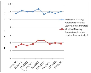
Victor Mwango BowaAbstract: In hard rock mining, blasting is the most productive excavation technique applied to fragment insitu rock to the required size for efficient loading and crushing. In order to blast the insitu rock to the desired fragment size, blast design parameter such as bench height, hole diameter, spacing, burden, hole length, bottom charge, specific charge and rock factor are considered. The research was carried out as a practical method on Nchanga Open Pits (NOP) ore Bench to optimize the blasting design parameters that can yield the required fragmentation size thereby reducing the shovel loading times and maximizing efficiency of the subsequent mining unit operations such as hauling and crushing. Fragmentation characteristics such as the mean fragment size were measured by means of a digital measuring tape and predicated using the Kuznetsov equation and rock factor value of ore bench was calculated using Lilly, (1986) equations by means of rock characteristics. Traditional blasting design parameters were acquired for NOP and modified using Langerfors and Sharma, P.A approaches. Several blast operations were conducted using both traditional and modified blasting design parameters on the same ore bench with the same geological conditions. Loading times of the shovel and fragment sizes were obtained after the blasts from ore bench where both the traditional and modified blasting design parameters were applied. Results show that mean fragment size and loading times were reduced from 51cm and 12minutes to 22cm and 3minutes where traditional and modified blasting design parameters were applied respectively.
Keywords: NOP=Nchanga Open Pits, Fragment Size, Loading Time, Ore Bench
————————————————————
1.0 Introduction
In open pit mining where rock is hard such that ,it requires drilling and blasting techniques to be applied for it to be mineable, the overall cost-effectiveness of the production operations requires that drilling and blasting be optimized. Mining costs for unit operations which includes loading, hauling, crushing costs reduce with increasing rock fragmentation sizes. Quality of blast results in open pit bench blasting plays a key effect on the efficiency and cost of drilling and blasting and subsequently mining unit operations such as loading and hauling, later on crushing operations.Quality of rock fragmentation depends on two sets of variables namely;
a) Rockmass properties which is a natural factor and cannot be controlled.
b) Blasting parameters; this can be controlled.
The total cost of ore production in open pit mining has a minimum value at an optimized fragmentation size. Prediction of the optimum fragmentation size is very important in selecting the right blasting parameters at a known cost and also in selecting the crusher and hauling sizes and types.In order to predict the blast result the Kuz-Ram model is generally used. The Kuz-Kuz-Ram model is generally an empirical fragmentation model based on the Kutnetsov (1973) and Rosin and Rammler equations modified by Cunningham (1983), which derives the coefficient of uniformity in the Rosin and Rammler from blasting parameters. Rock properties, explosive properties and design parameters are combined in this model of
Kuz-Ram fragmentation model.
1.1 The Kuznetsov Equation
The breakage quantity of rock with the applied known amount of explosive energy can be estimated using Kuznetsov’s equation. Kuznetsov equation (1973) was modified by Cunningham (1987) for ANFO based on equation 1 below;
0.8 0.167 0.633
(115 /
)
...(1)
m E ANFO
X
AK
Q
S
Where;
X
m=mean fragment size (cm),A
= BlastabilityIndex (rock factor),
K
=powder factor (specific charge, kg ofexplosive /
m
3,Q
E=mass of explosive being used (kg),ANFO
S
=the relative weight strength of the explosive relative to ANFO. The Blastability Index (rock factor) is calculated from an equation originally developed by Lilly (1986) shown in equation (2).It is used to modify the average fragmentation based on the rock type and blast direction.Where
A
=Blastability Index,RMD
=Rockmass description,JF
=Joint factor,RDI
=Rock Density Index,HF
=Hardness factorHF
is normally calculated by geotechnical engineers from geological data such as insitu block size ,joint spacing, joint orientations, rock specific gravity ,young’s modulus ,unconfined compressive strength. The powder factor (specific charge) is the mass of explosives being used (kg) to break a cubic meters volume of rock and is calculated using equation 3 below.0
K
Q /
EV
...(3)
Where;
Q
E=mass of explosives being used (kg),V
0=rockvolume (
m
3)0.06(
)...(2)
A
RMD
JF
RDI
HF
____________________
Victor Mwango Bowa
46 1.2 The Rosin and Rammler Equation
The material size distribution is calculated using the Rosin and Rammler equation shown in equation 4 below. Rosin and Rammler equation is commonly used in mineral processing area. (Rosin and Rammler, 1933).
(X/X )
Y 100(1
e
cn)...(4)
Where
Y
= % of material less than the size X(%),X=diameter of the fragment(cm),Xc=characteristic size (cm),
e
=base of natural algorithms n=the Rosin and Rammler exponent (uniformity coefficient).From Kuznetsov formulae,
X
mis the screen size for which50% of the material would pass? By using Rosin and Rammler equation, the characteristic size is calculated from
the average size by substituting x=
X
m and y=0.5 intoequation 4 which results into equation 5 below. 1/
X
C
(
X
m/ 0.693 )...(5)
n
An average particle size of the materials obtained from a blasting operation does not grantee enough information to explain the efficiency of the blasting operation. There are chances that there are more broken piles having same average particle size distributions. Very coarse and fine particles may result into acceptable average particle size but may be costly to handle in subsequent operations. Uniformity in particle size distribution is an important parameter that has to be considered. The uniformity coefficient is calculated from an equation 6 developed by Cunningham (1983) shown below. Cunningham established the applicable uniformity coefficient through several investigations taking into account the impacts of factors such as; blast geometry, hole diameter, burden, spacing, hole length and drilling accuracy. The exponent n for the Rosin and Rammler equation is estimated as shown in equation 6;
0.5
1
(2.2 14
)
(1
)(
)...6
2
S
B
B
W
L
n
D
B
H
Where; B=Blasting Burden (m), S=Blast hole spacing (m), D=blast hole diameter (mm), W=standard deviation of the drilling accuracy (m), L=total charge length (m), H=Bench height (m).Cunningham (1987) notes that the uniformity coefficient n usually varies between 0.8 and 1.5
1.3 Bench Blasting Parameters
Bench blasting in open pit operations are classified according to their purpose. Sometimes controlled bench blasting includes;
a) Smooth blasting which refers to lightly loaded holes that have been drilled along excavation limits and are shot after the main excavation is mined out.
b) Line drilling and blasting involves the drilling of closely spaced holes along the limit of the excavation. This provides a plane of weakness to which a primary blast may break.
c) Cushion Blasting (Trim Blasting) is similar to smooth blasting in that the holes are shot after the main production shot.
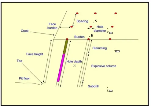
Open pit bench blasting is classified based on the diameter of the blast hole group like as follows; Small diameter blasting; from 65mm to 165mm and large diameter blasting; from 180mm to 450mm. For this study, small diameters holes are used at Nchanga Open Pits for the ore bench blasting. Many formulae and methods for calculating geometric parameters such as burden, spacing and subdriling have been around from early 1940s. Despite having many methods of designing and calculating the layout of a blast pattern, the author follows a particular method according to Sharma,P.A,2008 and small Blasting Swedish method developed by Langerfors and Kihlstrom (1976) are used (Jimeno et at ,1995) . Different explosive suppliers and mining companies may use different methods which may not be correct but all lead to the same blast results. Blast design is not a science; practical experience is more important in predicting the blast results. Figure 1 below shows the factors that are considered in generating a blast design. Many researchers have considered the common factors in designing the blast layouts for benches in Open Pits. According to Sharma P, A (2008) and Langerfors and Kihlstrom (1976) used by (Jimeno et at, 1995) the following factors and formulae apply;
Powder Factor is used to calculate size of the charge that will ensure safe and satisfactory blast results. The actual powder factor is calculated after all blast parameters have been determined to assist in calculating the total amount of explosives used in a blast. Formula 7 below shows how Powder factor is calculated using factors shown in figure 1 below.
*
K
...7
* *
C sL
J
M
B S H
Where
K
s=actual powder factor, L=Charge Length,J=subdriling,
M
C=charge mass, B=Burden, S=spacing,H=Bench height.
Figure 1: Parameters considered in open pit bench blast
design modified after (Anon, 2012)
, T
, U , S
H ,
Charge mass per unit length (Mc); is the amount of explosives in one meter hole with a specific diameter. The density of the explosives should be known. According to Sharma, P.A (2008), Charge mass per meter is calculated using formula 8 below.
2
...8
1273
C
D
M
Where
M
C=charge per meter, D=charge hole diameter,(mm)
=explosive density, g/cm
2Stemming, T acts as a seal, holds in the detonation gasses until the explosive has detonated completely and the rock starts to break. Stemming can be calculated from rule of thumb of 20-30 hole diameter or 0.2 to 0.5 times the burden or from formula 9 below after Sharma, P.A (2008).
1/3
12
*
*(
*
) ...9
100
E
T
Z
W
A
Where Z=Fly rock factor, which is normally 1 for normal blasting, 1.5 for controlled blasting. W=Mass of explosives in 8 hole diameter, E=Relative effective energy.
Charge Length, L this is calculated using formula 10 while the burden and spacing shown in figure 1 above is calculated using formula 11 above.
...10
...11
L
H
T
S
a
B
From practical experience,
a
is normally taken as 1.25resulting into
S
1.25
B
,where S=spacing and B=burdenwhere
a
= 1.25 is the coefficient.Sub drill is the length of hole drilled below floor level. This ensures that the full length of the hole is removed down to the floor level. Sub drill is normally 0.3 x burden or 8 to 12 hole diameters.
2.0 Information about Nchanga Open Pit
mines
Nchanga Open Pit mines are located in Chingola, in the Copperbelt province of Zambia. Open Pit mining at Nchanga started in 1938, in the main Nchanga Open Pit. More than a decade ago, Nchanga Open Pit was the largest base metals open cut in the world. It is still among the top five largest open cuts in the world. The mine’s core business is cobalt/copper cathode production. The pit runs benches of about 15m high, 8-10m berms width; the face angles are dictated by the geological conditions varying from 30˚ to 70˚ from weak to very competent rocks respectively. When drilling and blasting is conducted on ore bench, the drilling and blast design parameters are done differently from the waste drilling and blasting by mine
owners. In ore, holes are drilled using 165mm diameter bit size, spacing by burden are 6 x 7.2 m respectively, primers used are U500ms and pentolite boosters with solar ANFO. The powder factor used in ore is 0.68kg/BCM. At Nchanga Open Pits, the Loading time for ore was investigated and averaged at 12minutes for a shovel to do 3scoops and fill one Dump Truck. The high loading time was caused by poor rock fragmentation. As a result of high loading time caused by poor rock fragmentation, a study to optimize ore bench blasting parameters was conducted for Nchanga Open Pits.
3.0 Methodology
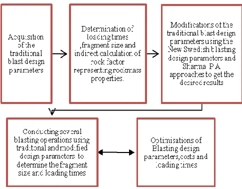
Research methodology is given in figure 2 as a work sheet below.
Figure 2: General layout of the research work sheet
Ore Bench Blasting design parameters which give the desired fragmentation size and normal loading times were optimized using the practical method, described in the work sheet in figure 2. The mean fragment size (cm) was calculated using the original equation, developed by Kuznetsov (1973), modified by Cunningham (1987).The rock factor value was obtained indirectly using Kuz-Ram model by means of design parameters and fragment size. The blast design parameters used by the mine owners in ore bench blasting were obtained and later modified using Sharma, P.A and Langefors and Kihlstrom (1976)’s Swedish new method blasting design parameter approaches now that the rock factor is known. Several blasting operations were conducted using both the traditional blast parameters and the modified blast parameters and their fragmentation size and loading times determined and analyzed respectively.
4.0 Optimization of Blasting Parameters
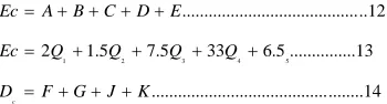
48 blasting cost obtained using equations 12, 13 and 14 using
variables shown in table 2.
1 2 3 4 5
...12
2 1.5 7.5 33 6.5 ...13
...14
c
Ec A B C D E
Ec Q Q Q Q
D F G J K
Where
D
c=Total drilling cost andEc
is the total blastingcost. In this research, blast hole diameter(mm),Burden(m) ,Blast hole spacing(m),subdriling(m),blast hole patterns and explosive properties were considered according to the desired fragmentation patterns in both traditional and modified blasting design parameters summarized in table 1. Optimization criteria required was to minimize loading time, mean fragment size and (Drilling and Blasting) cost. Optimization process can be defined as:
Minimize;
{
X
m
AK
0.8Q
E0.167(115 /
S
ANFO)
0.633} {Loading Time =Time taken by the shovel to fill 1 dumptruck}
Constraints; Rock Factor = 13.0, Bench Height = 6m Burden = 6m Spacing= 7.2 m Stemming= 2m charge length=5m Relative weight strength for ANFO= 100
Figure 3: Drilling and blasting plan and blast results obtained by using both traditional and modified blasting design parameters.
Table 1: Traditional and modified Blast design parameters
Traditional blast design parameters
Modified Blast design parameters.
Parameter Value Parameter Value
Rock Type TFQ Rock Type TFQ
Bench Height 6 Bench Height
Primer: U500ms + Pentolite
boosters
Primer: U500ms + Pentolite
boosters
Blast hole Diameter (mm) 165 Blast hole Diameter (mm) 165
Blast hole Length(m) 8 Blast hole Length(m) 7
Burden (m) 6 Burden (m) 5.4
Blast hole Spacing 7.2 Blast hole Spacing 6.2
ANFO length (m) 5 Emulsion charge length (m) 4.2
Stemming Length (m) 2 Stemming Length (m) 1.8
Weight of ANFO charge (kg) 305 Weight of Emulsion charge (kg) 180
Linear Charge per ,kg/m 35 Linear Charge per ,kg/m 28.81
Powder factor,kg/BCM 0.68 Powder factor,kg/BCM 0.5
Mean fragmentation size (cm) 51 Mean fragmentation size (cm) 22
Uniformity Coefficient 1.5 Uniformity Coefficient 0.85 Total Drilling -Blasting Cost
USD/m³) 2.7
Total Drilling -Blasting Cost
USD/m³) 3.2
Table 2: NOP Ore bench drilling and blasting cost components
Ore Bench -Blasting Cost Ore Bench-Drilling Costs
Cost Item Sym Quantity Unit Unit Cost Item Sym Unit cost Solar
Emulsion A Q1 Kg
2.00 USD /KG
Yield of
Depreciation F 100.00USD/blast Solar
Boosters B Q2 Kg
1.50 USD
/kg Fuel Cost G 0.6 USD/m
U500ms
(Detonators) C Q3 per /item
7.50 USD /Detonator
Personal
Expenses I 0.15 USD/m
Blast results
obtained by using
traditional blast
design parameters
50 Snap lines D Q4 Quantity of
snap lines
33.00 USD /100m
Cost of
Maintenance J 0.5USD/m
Firing
accessories E Q5 per /item
6.5 USD /per blast
fuel Cost on machine
moving
K 0.2 USD/m
Total Blasting Cost
Ec Total Drilling
Cost Dc
Figure 4 below shows loading times of the shovel for blasted material using both traditional and modified blast design
parameters on different dates.
Figure 4: Shovel loading times for blasted material using both traditional and modified blast design parameters on different
dates.
5.0 Results and Discussions
Optimum blast design parameters were determined by optimization of the traditional blast parameters using Sharma , P.A (2008 ) and Langefors and Kihlstrom (1976)’s Swedish new method open pit blasting design parameter approaches which predicated the required fragment size thereby reducing the loading times of the shovel and improved efficiency of subsequent hauling and crushing operations. However, this approach predicted relatively higher total costs on drilling and blasting since there will be more holes to be drilled ,charged and blasted when the modified blasting design parameters are applied. Blast results from modified blast design parameters show that can be applied to optimize the traditional blast design parameters for the ore bench at Nchanga Open Pits to reduce the fragment size and loading times, hence maximize hauling and crushing times for the unit operations of mining in ore. Rock factor on behalf of rockmass properties of the ore bench was determined indirectly by the
resultant fragmentation of the blasting operations carried out using both traditional and modified blast design parameters.
6.0 Acknowledgement
This research was supported by Nchanga Open Pits Technical Team with a view of reducing mining and crushing operations costs. Many thanks go to Professor Cheng Kang, School of Civil Engineering and Architecture, Wuhan University of Technology, Wuhan, China who tirelessly offered technical advice on the research.
7.0 References
[1] Bowa, M.V .2013. Modified Standard Operations
Procedure on Drilling and Blasting at Nchanga Open Pits, Drilling and Blasting Section, Konkola Copper Mines KCM, Chingola Zambia.
L
o
a
d
i
n
g
[2] Cunningham, C.V.B.1987.The Kuz-Ram model for prediction of fragmentation from Blasting. In R.
Holmberg and A. Rustan (editions).Prc 1st
International .Symposium on Rock fragmentation by blasting, Lulea University, Sweden 22-26August,pp 439-453
[3] Kuznetsov, V.M.1973.The mean diameter of the
fragments formed by blasting rock. Soviet Mining Science 9(2);144-148
[4] Langerfors, U and Kihlstrom, D .1976. The modern
Techniques of Rock Blasting, 3rd Edition. New York; John Wiley and son.
[5] Lilly, P.A .1986.An empirical method of assessing rock mass Blastability. In J.R Davidson (ed), proc. Large open pit mining conf., October, Pp89-92.Park ville, Victoria; The Aus IMM.
[6] Rosin, R and Rammler E. 1933.Laws governing
the fines of poedered coal; inst of fuel 7:29-36
[7] Sharma, P.D. 2008. Controlled Blasting
Techniques – Means to mitigate adverse impact of blasting in Open pits, Quarry, Tunnel, UG metal
mines and construction workings; Mining