IJEDR1701019
International Journal of Engineering Development and Research (www.ijedr.org)119
Design and Analysis of Intelligent Braking System
Mr. Tushar Kavatkar1 Mr. Harshal Salvi2, Mrs. Minal Rahate3 1,2Assistant Professor, 3Lecturer
1,2Department of mechanical Engineering, Finolex Academy of Management & Technology, Ratnagiri, 415639 3Department of Electronics & Telecommunication Engineering, Rajendra Mane Polytechnic Devrukh, Ratnagiri, 415639 ________________________________________________________________________________________________________ Abstract: The braking system was designed and applied on a car to make the driving process safety using embedded system design. Most of the accident occurs due to the delay of the driver to hit the brake, so in this project work braking system is developed such that when it is active it can apply brake depending upon the object sensed by the ultrasonic sensor and speed of vehicle. Currently, vehicles are often equipped with active safety systems to reduce the risk of accidents, many of which occur in the urban environments. The most popular include Antilock Braking Systems (ABS), Traction Control and Stability Control. All these systems employ different types of sensors to constantly monitor the conditions of the vehicle, and respond in an emergency situation. An intelligent mechatronic system includes an ultrasonic wave emitter provided on the front portion of a car producing and emitting ultrasonic waves frontward in a predetermined distance. An ultrasonic receiver is also placed on the front portion of the car operatively receiving a reflective ultrasonic wave signal. The reflected wave (detected pulse) gives the distance between the obstacle and the vehicle and RPM counter gives speed of vehicle. The microcontroller is used to control the braking of the vehicle based on the detection pulse information to push the brake pedal and apply brake to the car stupendously for safety purpose.
Keywords: Ultrasonic Sensor, Intelligent Mechatronic system, RPM counter, Microcontroller.
________________________________________________________________________________________________________
1. INTRODUCTION
Braking systems of commercial vehicles were always given the highest importance concerning safety issues and in particular active safety. Inappropriate braking of these vehicles may cause heavy accidents due to relatively longer stopping distances and higher energy output of brakes particularly in the case of vehicle combinations. The traditional medium used for brake system (compressed air) can be now controlled with the speed and precision offered by modern electronic abilities. Intelligent Braking System (IBS) introduced in commercial vehicles providing rapid brake response and release for every single wheel therefore ensuring safety. The extremely rapid response time provided by the electronic control can be used for crucially shortening the braking distance by introducing advanced control of braking system operation. Such a complex task imposed to the control of braking system cannot be based on the driver abilities and need to be done independently of the driver. An improved IBS braking forces management would certainly enable to reach the given task. The advanced strategy for the braking force management, proposed here, is based on intelligent controlling of the braking forces distribution between the front and rear axle of power-driven vehicle and/or between towing/trailer combination and/or between tractor/semi-trailer. Intelligent braking system has a lot of potential applications especially in developed countries where research on smart vehicle and intelligent highway are receiving ample attention. The system when integrated with other subsystems like automatic traction control system, intelligent throttle system, and auto cruise system, etc. will result in smart vehicle maneuver. The driver at the end of the day will become the passenger, safety accorded the highest priority and the journey will be optimized in term of time duration, cost, efficiency and comfortability. The impact of such design and development will cater for the need of contemporary society that aspires quality drive as well as to accommodate the advancement of technology especially in the area of smart sensor and actuator. The emergence of digital signal processor enhances the capacity and features of universal microcontroller. The overall system is designed so that the value of inter-vehicle distance from infrared laser sensor and speed of follower car from speedometer are fed into the DSP for processing, resulting in the DSP issuing commands to actuator to function appropriately [1]. The most popular systems like Antilock Braking Systems (ABS), Traction Control and Stability Control employ different types of sensors to constantly monitor the conditions of the vehicle, and respond in an emergency situation. An intelligent mechatronic system includes an ultrasonic wave emitter provided on the front portion of a car producing and emitting ultrasonic waves frontward in a predetermined distance. An ultrasonic receiver is also placed on the front portion of the car operatively receiving a reflective ultrasonic wave signal. The reflected wave (detected pulse) gives the distance between the obstacle and the vehicle. Then a microcontroller is used to control the speed of the vehicle based on the detection pulse information to push the brake pedal and apply brake to the car stupendously for safety purpose [2].
1.2 SYSTEM SURVEY
IJEDR1701019
International Journal of Engineering Development and Research (www.ijedr.org)120
driver not braking at same rate. Hence concluded that braking system present on vehicle are either so advance that they take the braking control away from driver and increase the risk factor or some of them are not that much advance to perform precisely, so we decided to make such system which can allow the driver brakes manually at the same time system also controlling the brakes to reduce risk factors in panic situation. An ABS can be expensive to maintain. Expensive sensors on each wheel can cost hundreds of dollars to fix if they get out of calibration or develop other problems. For some, this is a big reason to decline an ABS in a vehicle. Moreover many commuter vehicles in India don’t have the option of ABS because it’s very expensive. It's easy to cause a problem in an ABS by messing around with the brakes. Problems include disorientation of the ABS, where a compensating brake sensor causes the vehicle to shudder, make loud noise or generally brake worse. ABS can only help if the rider applies it in the right time manually and maintains the distance calculations. ABS has its own braking distance. Volvo’s laser assisted braking could not work effectively in rainfall and snowfall season and laser is easily affected by atmospheric conditions. In our project we are using Ultrasonic sensors and Microcontroller with which the speed of the vehicle is automatically reduced and voice alarms are given to the user when it approaches an object by automatically sensing the position of the object/vehicle.2 METHODOLGY
An intelligent mechatronic system includes an ultrasonic wave emitter provided on the front portion of a car producing and emitting ultrasonic waves frontward in a predetermined distance. An ultrasonic receiver is also placed on the front portion of the car operatively receiving a reflective ultrasonic wave signal. The reflected wave (detected pulse) gives the distance between the obstacle and the vehicle. The microcontroller is used to control the speed of the vehicle based on the detection pulse information to push the brake pedal and apply brake to the car stupendously for safety purpose. The extremely rapid response time provided by the electronic control can be used for crucially shortening the braking distance by introducing advanced control of braking system operation. The control of commercial vehicle’s braking system operation is related not only to vehicle speed but also to lateral acceleration together with the yaw moment control and significantly reducing the possibilities of the vehicle rolling over. Obviously, such a complex task imposed to the control of braking system cannot be based on the driver abilities and need to be done operated independently of the driver.
• Development of an idea • Detail study of literature • System survey
• Drawbacks in existing approach
• Cost estimation and specification for standard parts • Load distribution analysis
• Braking force and pressure analysis • Experimentation
• Results and discussion
IJEDR1701019
International Journal of Engineering Development and Research (www.ijedr.org)121
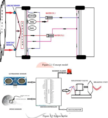
Figure 2.1 Concept modelFigure 2.2 System layout
Figure 2.1shows concept model of project. We are trying to actuate braking system automatically. Figure 2.2 shows Ultrasonic sensor, RPM counter and Microcontroller to control to take the decision of braking at right time. Actuator cylinder exerts required braking pressure on master cylinder.
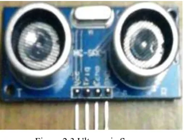
2.2 PRINCIPAL COMPONENTS OF INTELLIGENT BRAKING SYSTEM ULTRASONIC SENSOR
IJEDR1701019
International Journal of Engineering Development and Research (www.ijedr.org)122
Figure 2.3 Ultrasonic SensorTest distance = (high level time × velocity of sound (340M/S) / 2, Summary
Working Voltage DC 5 V Working Current 15mA Working Frequency 40Hz Max Range 4m Min Range 2cm Measuring Angle 15 degree
Trigger Input Signal 10uS TTL pulse
Echo Output Signal Input TTL lever signal and the range in proportion Dimension 45*20*15mm
TIMING DIAGRAM
Timing diagram is shown below. You only need to supply a short 10Us pulse to the trigger input to start the ranging, and then the module will send out an 8 cycle burst of ultrasound at 40 kHz and raise its echo. The Echo is a distance object that is pulse width and the range in proportion .You can calculate the range through the time interval between sending trigger signal and receiving echo signal. Formula: uS / 58 = Centimetres or uS / 148 =inch; or: the range = high level time * velocity (340M/S) / 2; we suggest to use over 60ms measurement cycle, in order to prevent trigger signal to the echo signal.
Figure 2.4 Timing diagram of Ultrasonic sensor
Ultrasonic ranging module HC - SR04 provides 2cm - 450cm non-contact measurement function, the ranging accuracy can reach to 3mm. The modules includes ultrasonic transmitters, receiver and control circuit.
IJEDR1701019
International Journal of Engineering Development and Research (www.ijedr.org)123
Using IO trigger for at least 10us high level signal. The Module automatically sends eight 40 kHz and detect whether there is a pulse signal back. If the signal back, through high level, time of high output IO duration is the time from sending ultrasonic to returning.PROCESSOR (ARDUINO UNO)
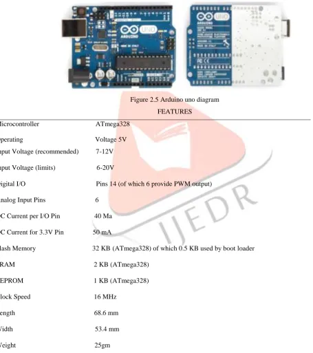
The Arduino Uno is a microcontroller board based on the ATmega328. It has 14 digital input/output pins (of which 6 can be used as PWM outputs), 6 analog inputs, a 16 MHz ceramic resonator, a USB connection, a power jack, an ICSP header, and a reset button. It contains everything needed to support the microcontroller; simply connect it to a computer with a USB cable or power it with a AC-to-DC adapter or battery to get started. "Uno" means one in Italian and is named to mark the upcoming release of Arduino 1.0. The Uno and version 1.0 will be the reference versions of Arduino, moving forward. The Uno is the latest in a series of USB Arduino boards, and the reference model for the Arduino platform; for a comparison with previous versions.
Figure 2.5 Arduino uno diagram FEATURES
Microcontroller ATmega328 Operating Voltage 5V Input Voltage (recommended) 7-12V Input Voltage (limits) 6-20V
Digital I/O Pins 14 (of which 6 provide PWM output) Analog Input Pins 6
DC Current per I/O Pin 40 Ma DC Current for 3.3V Pin 50 mA
Flash Memory 32 KB (ATmega328) of which 0.5 KB used by boot loader SRAM 2 KB (ATmega328)
EEPROM 1 KB (ATmega328) Clock Speed 16 MHz
Length 68.6 mm Width 53.4 mm Weight 25gm
RPM COUNTER (H 2010 OPT COUPLER PHOTOELECTRIC SENSOR) Specifications;
IJEDR1701019
International Journal of Engineering Development and Research (www.ijedr.org)124
3. Counter limit -5000rpm
Figure 2.6 Rpm counter Figure2.7 DC Motor linear actuator DC MOTOR LINEAR ACTUATOR
Specifications:
Voltage: 12V DC
Stroke length: 2 inch
Duty cycle: 25%
Max load current: 3 Amp
No load current < 1 Amp
STEP DOWN LOW FREQUENCY TRANSFORMER Specifications:
Power: 0.5 V-amp to 200 V-amp Coil structure: Toroidal
Phase: Single phase
Winding turns: Encapsulated Transformer / Autotransformer Cooling: Air cooled
Figure 2.8 12V 2Amp Transformers Figure 2.9 Interfacing of sensor with microcontroller Figure 2.10 Power Supply circuit.
IJEDR1701019
International Journal of Engineering Development and Research (www.ijedr.org)125
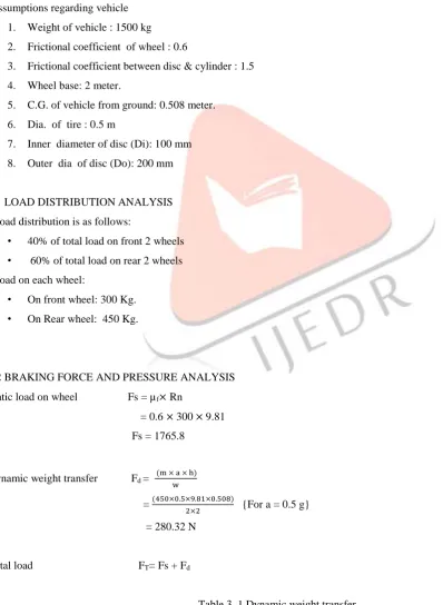
Figure 2.11 Force distributionAssumptions regarding vehicle 1. Weight of vehicle : 1500 kg 2. Frictional coefficient of wheel : 0.6
3. Frictional coefficient between disc & cylinder : 1.5 4. Wheel base: 2 meter.
5. C.G. of vehicle from ground: 0.508 meter. 6. Dia. of tire : 0.5 m
7. Inner diameter of disc (Di): 100 mm 8. Outer dia of disc (Do): 200 mm
3.1 LOAD DISTRIBUTION ANALYSIS Load distribution is as follows:
• 40% of total load on front 2 wheels • 60% of total load on rear 2 wheels Load on each wheel:
• On front wheel: 300 Kg. • On Rear wheel: 450 Kg.
3.2 BRAKING FORCE AND PRESSURE ANALYSIS Static load on wheel Fs = µf× Rn
= 0.6 × 300 × 9.81 Fs = 1765.8
Dynamic weight transfer Fd = (m × a × h)
w = (450×0.5×9.81×0.508)
2×2 {For a = 0.5 g} = 280.32 N
Total load FT= Fs + Fd
IJEDR1701019
International Journal of Engineering Development and Research (www.ijedr.org)126
Sr.No. Acceleration (a) Dynamic weight transfer1 0.5g 280.32 N
2 1.2g 672.76 N
3 2.0g 1121 N
4 3.7g 2074 N
Table 3. 2 Total load
Sr. No. Acceleration (a) Total load (Ft) N Torque (T)=Ft * r
1 0.5g 2046.12 511.53
2 1.2g 2438.56 609.64
3 2.0g 2887 721.75
Clamp Load C = Torque
µf × Re × n { Where Re = Ri + Ro
2 = 100 + 50
2 } = 511.53
1.5 ∗0.75 ∗2 = 2273.46 N
Table 3. 3 Clamp Load
Sr.No. Acceleration (a) Clamp Load
1 0.5g 2273.46
2 1.2g 2709.51
3 2.0g 3207.77
4 3.7g 4266.84
System pressure required P = Clamping Load Area
Area A =π
4× 0.025 2× 2
= 9.8174 × 10⁻⁴ m2
Table 3. 4 System pressure required
Sr. No. Acceleration (a) System pressure (bar)
1 0.5g 23.15
2 1.2g 27.59
IJEDR1701019
International Journal of Engineering Development and Research (www.ijedr.org)127
4 3.7g 43.46
Calculations of required deceleration rate for various allowable distances
Table 3. 5 deceleration rate for various allowable distances Dist.
Speed
S=10m S=8m S=6m S=4m
60-55 0.226g 0.2823g 0.3769g 0.564g
60-50 0.432g 0.54g 0.72g 1.081g
60-45 0.618g 0.772g 1.029g 1.545g
60-40 0.7855g 0.981g 1.308g 1.96g≈2.0g
60-35 0.933g 1.166g 1.55g 2.32g
60-30 1.06g 1.326g 1.767g 2.65g
60-25 1.168g 1.461g 1.948g 2.919g
60-20 1.256g 1.57g 2.09g 3.149g
60-15 1.314g 1.634g 2.166g 3.379g
Table 3. 5 deceleration rate for various allowable distances
Dist.
Speed
S=10m S=8m S=6m S=4m
40-35 0.1475g 0.1844g 0.2459g 0.368g
40-30 0.275g 0.344g 0.459g 0.688g
40-25 0.3836g 0.4795g 0.639g 0.959g
40-20 0.4721g 0.59g 0.7868g 1.18g≈1.2g
40-10 0.59g 0.739g 0.986g 1.479g
40-00 0.6291g 0.7863g 1.0485g 1.572g
Table 3.5 deceleration rate for various allowable distances Dist.
IJEDR1701019
International Journal of Engineering Development and Research (www.ijedr.org)128
20-10 0.62g 0.897g 0.1138g 0.2346g
20-00 0.1569g 0.1962g 0.2616g 0.3924g≈0.5g
4 EXPERIMENTATION
Our future course of action is to assemble a system on vehicle & perform various experimentations by varying different parameters. Those parameters are as follows:
Vehicle Speed Obstacle distance Sensor Position
Varying deceleration rate
In Order To Avoid Jerky Motion of the vehicle due to sudden braking, we can use combinations of different flow rates to achieve smooth braking and avoid vibrations and for faster response of system we can use electronically operated flow control valve which may add extra cost to the system.
.
Figure 4.1 Braking fluid distributions DRAWBACKS IN USING HYDRAULIC ACTUATION
1. Actuation time and response time required is more which makes the system less effective. 2. Requires more components
3. System becomes more complex and installation is bit difficult. 4. Add unnecessary weight in vehicle.
5. More expensive.
Because of the above reasons we switched over to electrically actuated solenoid which has following advantages: 1. Response time required is less.
2. Require very less components as compared to hydraulic actuation. 3. System becomes simpler.
4. Less expensive.
IJEDR1701019
International Journal of Engineering Development and Research (www.ijedr.org)129
Figure 4.2 Schematic setup Figure 4.3 Schematic setup
ACTUAL EXPERIMENTAL SETUP
Figure 4.4 Actual test bench Figure 4.5 Sensors position Figure 4.6 Rpm counter position
This is the experimental setup we created for the conclusions in our experiment the object is stationary where as the obstacle distance is varying in case of taking of reading when obstacle distance is varying.
ADVANTAGES OF INTELLIGENT BRAKING SYSTEM (IBS)
As mentioned above, an IBS prevents lock-ups and skidding, even in slippery conditions. IBS brakes have been proven to save lives in some situations by helping drivers keep control of a vehicle.
An IBS shares some of the infrastructure of a traction control system, where new technology helps ensure that each wheel has traction on the road. That makes it easy for manufacturers to install both of these features at the factory.
Intelligent braking systems coordinate wheel activity with a sensor on each wheel that regulates brake pressure as necessary, so that all wheels are operating in a similar speed range. And help drivers have better control of a vehicle in some road conditions where hard braking may be necessary.
• An ultrasonic sensor, cheaper and less demanding of hardware than other types of sensors presently used. • As ultrasonic sensors can detect any kind of obstacle, this system can also prevent collision of the vehicle with
pedestrians, or can at least reduce the injuries occurring.
• This lower cost of ultrasonic sensors compared with other kinds of sensors, could facilitate the application and mounting of the system in many low-end vehicles, helping to improve comfort and safety and offer a hassle free driving experience at a reduced cost.
• As system does not take whole control from driver, the ‘ risk ‘factor due to false indication gets reduced.
When vehicle is in motion, different forces acts on it during braking of vehicle. i.e. Sum of all the static and dynamic forces comes in picture .To achieve safe and smooth braking operation we works on different parameters as follows.
1. Obstacle distance:
IJEDR1701019
International Journal of Engineering Development and Research (www.ijedr.org)130
Figure 4.7 Graph of Speed Vs Stopping distance2. Current variation to actuator:
Actuator we used is of variable actuator speed i.e. from 3mm/sec to 20mm/sec. We can achieve this variation with the help of different current rating (1amp to 3amp) during high speed condition and critical braking condition we have to apply brake immediately but without jerk.
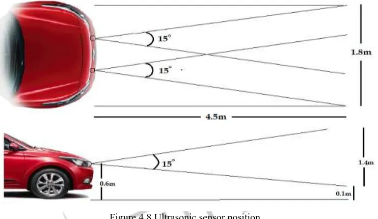
3. Ultrasonic Sensor position:
Figure 4.8 Ultrasonic sensor position
To get maximum catchment area in front of the vehicle and to avoid false indication we have to adjust the sensor position. Also number of sensors use is crucial parameter because if one sensor faces the failure then other can do the work.
5 DISCUSSIONS
In the present work, a prototype of an ultrasonic distance measurement for stationary obstacle is obtained. And controlling the speed of vehicle accordingly to predetermined distance is shown. An ultrasonic sensor, cheaper and less demanding of hardware than other types of sensors presently used, such as the sensors based on computer vision or radar , is used to measure the distance between vehicle and the obstacle. The relative speed of the vehicle with respect to the obstacle is estimated using consecutive samples of the distance calculated. These two quantities are used by the control system to calculate the actions on both the accelerator and also the brake, thus to adjust the speed in order to maintain a safe distance to prevent accidents. As ultrasonic sensors can detect any kind of obstacle, this system can also prevent collision of the vehicle with pedestrians, or can at least reduce the injuries occurring. Since the control system does not use the absolute speed to calculate the safety distance as done by the currently existing systems, the interaction with automotive electronics is limited to actions on the accelerator and brake. This matter, coupled with the fact of lower cost of ultrasonic sensors compared with other kinds of sensors, could facilitate the application and mounting of the system in many low-end vehicles, helping to improve comfort and safety and offer a hassle free driving experience at a reduced cost
6 CONCLUSIONS
IJEDR1701019
International Journal of Engineering Development and Research (www.ijedr.org)131
and microcontroller action plays vital role in determining intelligent braking torque generated by brake actuation assembly. Design of intelligent brake applications basically depend upon effectiveness of Ultrasonic sensor and RPM counter. In the present work various experiments were conducted to check the effect of various parameters such as obstacle distance, output current and sensor position on moving vehicle braking. The parameters were varied using different arrangements of sensors, varied amount of current which leads to various conclusions. In the present work, a prototype of an ultrasonic distance measurement for stationary obstacle is obtained. And controlling the speed of vehicle accordingly to predetermined distance is shown. An ultrasonic sensor, cheaper and less demanding of hardware than other types of sensors presently used, such as the sensors based on computer vision or radar , is used to measure the distance between vehicle and the obstacle. The speed of the vehicle is estimated using RPM counter. These two quantities are used by the control system to calculate the actions of the brake, thus to adjust the speed in order to maintain a safe distance to prevent accidents. As ultrasonic sensors can detect any kind of obstacle, this system can also prevent collision of the vehicle with pedestrians, or can at least reduce the injuries occurring. Since the control system does not use the absolute speed to calculate the safety distance as done by the currently existing systems, the interaction with automotive electronics is limited to actions on the accelerator and brake. This matter, coupled with the fact of lower cost of ultrasonic sensors compared with other kinds of sensors, could facilitate the application and mounting of the system in many low-end vehicles, helping to improve comfort and safety and offer a hassle free driving experience at a reduced cost. We have used the previous work on advance braking system and use that to define the basic braking control problem and have developed intelligent control method for this system. Clearly the approaches and conclusions that we present are somewhat preliminary and are in need of further significant investigations. For instance, it would be useful to perform stable, hastle free braking and also help to evaluate this safety-critical automotive braking system. While the model that we have developed has proven to be quite adequate for the development of microcontroller system that has been evaluated on a vehicle, it would be valuable to evaluate the developed controllers in the field. This would force us to take a very careful look at the requirements for real-time implementations of the intelligent braking system. Our present work realized us that implementation of this smart system can feasible and of real time use.Approaches and conclusions that we present are somewhat preliminary and are in need of further significant investigations. While car is taking a turn sensor can give the false indication of obstacle. To avoid this we will make an arrangement such that this system goes off while turn. This can be achieved by mounting sensors on car wheel that are capable of measuring wheel turning. At present, this system is readily suitable for automatic transmission. While making some changes we can use this on any available vehicle. Also improved and precise programming is necessary for real time operation. Application of intelligent braking system for critical dynamic condition need to be analysed.
7 REFERENCES
[1]” Hardware Implementation of Intelligent Braking System” Published By - S. N. Sidek and M. J. E. Salami, Faculty of Engineering, International Islamic University Malaysia.
[2] “Intelligent Mechatronic Braking System” Published By -. G.V. Sairam, B. Suresh, CH. Sai Hemanth, K. Krishna sai [3] Lennon,W.K., and. Passino,K.M . ” Ieee Transaction On Control System Technology”, VOL.7, NO.2, 1999
[4] Dr. Stephen Amell “IDEA Program Transportation Research Board National Research Council” ,May 31,1996
[5] C Govar , I Knight , F Okoro, I Simmons, G Coupr , P Massle, And B Smith presented “automatic energy brake system :
technical requirement , cost and benefits” PPR 227 VERSION 1.1
[6] Aleksendric, Dragan, University of balgrade, Faculty of mechanical engineering, Automotive Department , Serbia presented paper on “Intelligent Control Of Commercial Vehicle Braking System Function”
[7]www.sciencedirect.com/engg./automobile/brakingsystem/microcontrollerbraking
[8]www.ijetae.com/publish/201352/, VOL.3, ISSUE 4, APRIL 2013