INTERNATIONAL JOURNAL OF SCIENTIFIC & TECHNOLOGY RESEARCH VOLUME 4, ISSUE 07, JULY 2015 ISSN 2277-8616
44
Real-Time Vehicle Data Logging System
Using GPS And GSM
Win Minn Thet, MyoMaung Maung, Hla Myo Tun
Abstract: This paper proposes and implements a low cost Vehicle Data Logging System using GPS and GSM. This system allows a user to trace the present and past positions recorded in SD card. This system also reads the current position of the vehicle using GPS, the data is sent via GSM service from the GSM network. The vehicle’s position including the driving speed, the UTC time and data are stored in the SD card for live and past tracking. All of that GPS data is sent to PIC 18F4520 by the Universal Asynchronous Receiver/Transmitter (UART) and also store in SD card. GSM also uses UART to transmit. To know the position of the vehicle, the owner sends a request through a SMS. The SMS sends to the authorized person through the GSM network. The travel history of the vehicle are stored in a file on an SD card in FAT format.This system is very useful for car tracking, for adolescent driver being checked by parent (speed limit exceeding, leaving a specific area). V The developed system is easy to use, requires no additional hardware, and permits the selection of the amount of data and the time intervals between the data recordings. In addition, the collected data can easily be transferred to a computer via a connected serial port.
Keywords: GPS, GSM modem, SD Card, UART, FAT.
————————————————————
I.
I
NTRODUCTIONThis research describes the idea of logging the data of a vehicle using latest technology of GPS, GSM and SD card. Data logging is the process where a physical quantity such as the temperature, pressure, force, voltage, etc. are captured continuously at pre-defined intervals and then stored on some form of storage device, usually for future analysis. A vehicle data logger, which is also called vehicle monitoring system, is able to record the vehicle location autonomously over a distinct period of time and has multifarious applications in the any workplace. GPS data loggers are commonly used in tracking the movements of people, objects, or animals. For example, data loggers can be used to fine missing children, animals, or missing items such as cars. There are several commercially available GPS based data logging devices in the market. These devices basically include a built-in GPS receiver and electronics to capture the user geographical coordinates and store them either in the internal memory of the devices, or on an external memory card(e.g. and SD card). Mobile technologies such as GSM and GPS can be used for displaying the current position of the vehicle indicating as the latitude, longitude, the UTC time, data and driving speed. Global System for Mobile Communications (GSM) is the most common used service for this purpose. The Global Positioning System (GPS) to determine the precise location of a vehicle to which it is attached. The Storage Device Card (SD) is widely used as storage media for a portable device. During vehicle motion, the position data, the UTC time, date and driving speed are reported by a text message. These data of the vehicle can be seen in the user’s cell phone as the form of a SMS.
The travel history of the vehicle is stored in a file on SD card in FAT16 file system. The following are the objectives of the research project to ensure it meets the aim:
1. To acquire of vehicle’s location information
latitudeand longitude in real time
2. To display the vehicle location information to user on
GSM network by using SMS
3. To write a program that can send the SMS using
MikroC language in Proteus software
4. To design a circuit that can automatically store the
vehicle information on SD card
II.
D
ESIGN OFV
EHICLED
ATAL
OGGINGS
YSTEMIn this paper, it is proposed to design an embedded system which is used for tracking of any vehicle by using Global Positioning System (GPS), Global System for Mobile Communication (GSM) and Secure Digital Card (SD card). The block diagram of vehicle data logging system is shown in figure 1. This design is based around a PIC 18F4520 type advanced microcontroller. PIC 18F4520 microcontroller is used for interfacing to various hardware peripherals. PIC 18F4520 microcontroller is interfaced serially to a GSM modem and GPS receiver. A GPS receiver sends NMEA sentences to the microcontroller every seconds. The microcontroller receives the NMEA sentences, extract the $GPRMC sentence and then the position data (latitude and longitude), the driving speed, the UTC time and date are display on LCD. A Liquid Crystal Display (LCD) is attached to the microcontroller. At the same time, GPS data is still written to a file on the SD card continuously. SD card is implemented with FAT16 file system, which enables rapid file storage when developing an embedded system. The data of real-time collection can be stored on the SD card in the form of text by the file system in a short time. GSM modem is used for two way communications between the vehicle and the owner. GSM modem is used to send these data of the vehicle from a remote place as the form of SMS. The GPS receiver will continuously give the data i.e. the latitude and longitude indicating the position of the vehicle, driving speed, the UTC time and date. When the request by user is sent to the number at the GSM modem, the system automatically sends a return reply of the information of the vehicle to that mobile.
__________________
Win Minn Thet, MyoMaung Maung and Hla Myo Tun
Department of Electronic Engineering Mandalay Technological University 12wminnthet@gmail.com,
GPS
Receiver
LCD
SD Card
(latitude,
longitude, time,
date, speed)
GSM
modem
latitude,
longitude,
time, date,
speed
GSM Mobile
PIC
18F4520
from SatelliteFigure1. Block Diagram of Vehicle Data Logging System
III.
S
YSTEMD
ESIGN ANDI
MPLEMENTATIONThis system consists of three main parts: interfacing with PIC microcontroller, data storage on an SD card and transmission the vehicle location information to user’s cell phone by using SMS through GSM modem.
A. Objectives
The main aim of the system is to design and development of the advance vehicle data logging system in real time environment. The user can send a status message from his mobile phone and as soon as the GSM module gets the message, it will check the user’s authentication, it will immediately sends the details of the location like latitude and longitude, driving speed, date and UTC time using the GPS receiver. So the user can get to know the exact location and speed of the vehicle.
B. System Benefits
i. Vehicle owner can be tracked the exact location of
the vehicle using GPS receiver.
ii. This application includes checking for driving
performance of parent with a teen driver.
iii. If the vehicle is theft, the owner can be tracked the
vehicle by the used of GPS and GSM technology easily.
(1) GPS Receiver Module
The Gotop GT-1513-SF GPS/GNSS receiver is used in the design. This is a small, low-cost GPS receiver with the following features:
i. Built on high performance, low-power SIR FIII chipset
ii. Extremely fast TTFF at low signal level
iii. Low power consumption: Max 45mA@3.0V
iv. NMEA-0183 compliant protocol or custom protocol
v. Operates with 3.0V to 5.0V
Figure 2. GPS Receiver
The Gotop GT-1513-SF GPS module has four pins: pin 1 and 2 are the ground and the supply voltage respectively, pin 3 is the TTL compatible, non-inverted serial input-output pin. Pin 4 is the output format selection bit, called the RAW pin. When RAW is low, the GPS module sends out NMEA sentences automatically every second. When raw is high (or un-connected) specific GPS data (e.g. the latitude) can be requested from the device by sending commands. The data format is however fixed: X, N, 8, 1, i.e. X baud rate, no parity, 8 data bits and one stop bit. The module default baud rate is set up 9600 bps however, the user can change the default baud rate to any value from 4800 bps to 115k bps. The Gotop GT-1513-SF supports the following NMEA-0183 messages:
Table I
Common NMEA-0183 Sentences
NMEA
Record Description
GPGGA GPS DOP and active satellites
GPRMC Recommended minimum specific GPS
data
GNGSA GNSS DOP and active satellites
GNRMC Recommended minimum specific
GNSS data
GLGSV GPS/GNSS satellites in view
The data output from a GPS receiver is in ASCII text format and is known as the NMEA-0183, or simply the NMEA format. According to this format, navigational parameter is sent in the form of “sentences”, where each NMEA sentence starts with a “$” sign, each navigational parameter is separated by commas, and each sentence is terminated by two hexadecimal checksum characters. The NMEA sentences are usually sent out every second. The NMEA sentence used in this system is the $GPRMC, which has the following parameters: $GPRMC: Although there are some variations in its format, this sentence basically defines the basic navigation parameters, speed, course, date of fix, and magnetic variation. An example is:
$GPRMC,132031.000,A,2502.25585,N,12125.4856,E,12.81,3 54.81,100512,,,,A*51
(2) Microcontroller
low-46
power consumption design can satisfy the prolonged outdoor work. It is interfacing the device with GSM module, GPS receiver and SD card.
PIC
18F4520
1 2 3 4 5 6 7 8 9 10 11 12 13 14 15 16 17 18 19 20 40 39 38 37 36 35 34 33 32 31 30 29 28 27 26 25 24 23 22 21 +5V +5V VDD VSS VDD VSS For LCD display RB5 RB4 RB3 RB2 RB1 RB0 To GPS To GSMTo SD Card To SD Card
RD7 RD6 RC5 RC4 RD0 RD1 RC0 RC3 MCLR
Figure 3. PIC 18F4520 Microcontroller Pins Assign
(3) GSM Modem
Siemens TC35 GSM/GPRS modem is chosen for the wireless communication to inform the owner with the text messages. This modem fits the need of data transfer with SMS data communication, circuit switch for data connectivity, TCP/IP and etc. The AT command set and RS232 interface offered by GSM modem provide easy data connection without any extra circuit. However, a MAX232 chip needs to be connected as an interface between PIC microcontroller and GSM module through this RS232 connection. This GSM module supports a wide range of GSM bandwidth including 900 MHz and 1800 MHz. It uses a 5V DC voltage which is the basic power supply for all the other components in the proposed system, making it easier to be powered up with a shared battery. Figure4 shows an image of the GSM module that is used in the proposed system.
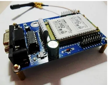
Figure 4. Siemens TC35 GSM/GPRS Modem
Siemens TC35 GSM/GPRS modem supports AT commands set which is the basic language for almost all wireless communication module and system. For an easy access and settings, the GSM modem can be interfaced with standard normal computer with RS232 serial port. By using several AT commands, the user can first test and configure the GSM module’s SIM card number.
The communication path between microcontroller and GSM module is UART. In proposed system the SMS message is send in text format. In order to send SMS, microcontroller must send the following commands:
AT+CMGF=1 OK
AT+CSCS= “GSM” OK
AT+CMGS= “+995---”
(4) SD card
The Secure Digital Card (SD) is the de facto standard memory card for mobile devices. The SD cards have basically a flash memory array and a (micro) controller inside. The flash memory controls (erasing, reading, writing, error controls and wear leveling) are completed inside the memory card. The data is transferred between the memory card and the host controller as data blocks in units of 512 bytes. The currently defined file system for the memory card is FAT16 file system. The system is equipped with a removable sending SD card, which is used for GPS data storage. Saving the acquired data by this type of storage media is appropriate not only because of its large capacity, but also because of the subsequent processing of stored data, which is performed in the service application on a PC of windows.
7 0 0 7 MOSI CLK CS MISO
PIC 18F4520 SD module
MSB LSB MSB LSB M A S T E R S L A V E
Figure 5. SPI Single Master/ Slave Application
In order for the system to read and write from the SD card, the SPI (Serial Peripheral Interface) from PIC microcontroller shown in figure. 5 is used. The number of signals of SPI (three or four wires) is larger than IIC’s two wires, but the transfer rate can rise up to 20 Mbps or higher depending on the device’s ability. The SPI interface permits communication with only four physical connections. The basic configuration consists of a clock signal, a MasterInSlave Out (MISO), a Master Out Slave In (MOSI), and a Slave Select (CS), besides 3.3 V and GND. The SD card is connected to PORTC pins of the microcontroller.
IV.
S
OFTWAREI
MPLEMENTATIONmobile including the position data, driving speed, the UTC time and date of the vehicle as the form of SMS. So, this system is to trace the location of the vehicle. The travel history of the vehicle is stored in a file on SD card in FAT16 file system.
Figure 6. Flowchart for Vehicle Data Logging System
V.
S
OFTWARET
ESTR
ESULTIn the system,MikroC programming and Proteus software are used for PIC 18F4520 microcontroller.PIC microcontroller is a special-purpose integrated circuit designed to perform one or a few dedicated function depending on the program code that has been written on it. Usually, a microcontroller will become the main brain for a complete system with its hardware and mechanical parts. The program code is written in programming language such as MikroC or BASIC that provides a structured mechanism for defining pieces of data and the operations or transformations that to be carried by microcontroller. The proposed system is written in MikroC programming language.MikroC is a powerful, feature rich development tool for PIC microcontrollers. MikroC makes a fast and reliable tool. Proteus software is used to illustrate the virtual circuit diagram. The overall circuit diagram is shown in figure 7. PIC 18F4520 1 2 3 13 14 15 17 18 19 20 38 37 36 35 34 33 30 29 24 23 V S S V D D V E E
RSRWED
0 D 1 D 2 D 3 D 4 D 5 D 6 D 7
1234567891011121314
GSM Modem RXD TXD RTS CTS GPS Input RXD TXD RTS CTS CS DI DO CLK M M C C a r d MCLR RA0 RA1 RA7 RA6 RC0 RC2 RC3 RD0 RD1 RB5 RB4 RB3 RB2 RB1 RB0 RD7 RD6 RC5 RC4 10K 10K 10K 5K R2 R1 R3 R4 1K 22pF 22pF C1 C2 XI CRYSTAL RV1 VI VO GND BAT1 12V 1000µF C3 100µF 0.1µF C4 C5 LM7805
Figure 7. Overall Circuit Diagram of Vehicle Data Logging
System
Software simulation for interfacing with GPS, GSM, SD card and PIC 18F4520 are described in figure 8 and 9. Firstly, the system is not receive the data from GPS receiver. So the initial state of the system will show on LCD. If the data is not in the correct format or before the signal is received from GPS, the LCD will show in initial state of the system as in figure 8.
Figure 8. Initial State of Simulation Test
48
Figure 9. Simulation Test for GPS and GSM Information
VI.
H
ARDWAREI
MPLEMENTATIONFigure 10 and 11 show the practical result with position, date, UTC time and speed information on LCD. In this hardware test, the GPS is configured to transmit at 9600 bits per seconds. GPS pin TX is connected to the microcontroller and GSM pins TX and RX are connected to microcontroller serial ports. In this system, GSM acts as a SMS receiver and sender. LCD is configured to show vehicle information from the microcontroller. The vehicle’s location and speed display on LCD are updated on every second. During the driving, the speed is also changed with the change of distance travel. The unit measured in speed is Kilometre per hour. When the request is sent to the GSM modem, the system automatically sends a return reply to the owner within 10 seconds in the form of SMS shown in figure 12. The following hardware is implemented in Mandalay Township, Myanmar. The latitude and longitude of Mandalay region is between 19 º 20´ to 23 º 45´ North and 94 º 45´ to 97 º 00´ East.
Figure 11. Hardware Test of Automobile Position and Speed
Tracking System
Figure 11. Position and Speed Information on LCD
Figure 12. Vehicle Location (Latitude and Longitude), Date,
Time and Driving Speed Information in the User GSM
The system obtains the vehicle’s data from the SD card, and it then inserts the SD card into the PC to view the trajectory history of a vehicle. This part is shown in figure 13.
Figure 13. Vehicle’s Position Information and Speed on SD
VII.
A
PPLICATION ANDA
DVANTAGEA. Applications
The GPS and GSM based Vehicle Data Logging System is one of the most important system. It is necessary due to the many of applications and wide usage of them bymillions of people throughout the world. Some application areas of the system are:
i. Anti-theft system for cars and bikes
ii. As a vehicle management software for transport
companies
iii. Hand-held device for personal positioning and travel
navigation
B. Advantages
The design of this system offers many advantages.
i. The owner can check the travel history of the vehicle.
ii. It provides more security than other system.
VIII.
C
ONCLUSIONIn this paper, real time vehicle data logging system using GPS and GSM is presented. The system included three main components: a transmitting embedded module to interface in-vehicle GPS, GSM module in order to determine and send the automobile location, driving speed and the UTC time information via SMS and store these information on SD card in the form of FAT file system. The data is precise and is always compatible with real time system as the satellites are continuously monitoring. On the whole system proves to be very successful and can be easily implemented in real time. The experimentation result shows that the system is very efficient and cost effective. So, the use of GSM and GPS technologies allows the system to track vehicle and provides the most up-to-date information about ongoing trips.
A
CKNOWLEDGMENTThe author wishes to extend grateful thanks to her supervisor, U MyoMaungMaung, Lecturer, Department of Electronic Engineering, Mandalay Technological University, for his helpful,instructions and supervision, critical reading of manuscript, and tolerance helped in all the time of this research work. The author specially thanks to all her teachers from Department of Electronics Engineering, Mandalay Technological University and her family for their supports and encouragement and also thanks to all her friends.
REFERENCES
[1] GPSImages[online:]http://www.gpsvehiclenavigation.
com/GPS/images.php
[2] Jr-Jen Huang, Yi-Yu Chu, and Yen-Jen Chen, “The
System Design and Implementation of Vehicle Management” Journal of Advances in Computer Networks, vol. 1, No. 1, March 2013J.
[3] Cui Youjing, “Autonomous vehicle positioning with
GPS in urban canyon environments,” IEEE Trans. Robotics and Automation, vol 19, no.2, pp.15-25, Singapore, Feb.2003.
[4] R. Bajaj, “GPS: location-tracking technology,” in Proc.
IEEE International Conf. on computer, San Francisco, USA , Apr. 2002, vol.35, issue 4, pp. 92-94.
PIC18FXX2 Data Sheet,“High Performance
[5] Dr.Kamal Jain and Rahul Goel”GPS Based Low Cost
Intelligent Vehicle Tracking System(IVTS)”, 2012
International Conference on Traffic and
Transportation Engineering(ICTTE 2012), IPCSIT vol.26.