767
An Arm Based 3d Concrete Printer
Sijila K , Anisha Tomson M, Dr.Aji Joy
Abstract: The construction industry is facing a drastic change in standard processing technologies and many construction automation methods such as 3D concrete printing (3DCP) merged in the construction field. 3DCP can allow flexible construction without the use of much expensive structure and materials. 3D concrete printing is an innovative construction method and has many advantages in the construction field such as reduction in construction time, reduction in cost, flexibility in designing, reduction in errors and environmental factors. Concrete is extruded through a nozzle and layer-by-layer concrete plates are formed to construct the model without the mold. Studies has been done to detect and resolve various design and operational problems faced in 3D concrete printing which would help in future development of the construction process. Goal of this project is to built an efficient and low-cost hardware structure which will print a 3D concrete cube using an algorithm. In this CNC machine, the XYZ movement controlled by an ARM microcontroller (LPC 1769) with software implemented on LPCXpresso using embedded C. The microcontroller converts G-code which was transmitted by UART from PC into machine language instruction which is to be sent to the motor driver of the CNC printer to print the model.
Keywords : ARM LPC 1769, Computer numerical control, Extruder, G-Code, 3D concrete printing, 3D Printer —————————— ——————————
1.
INTRODUCTION
Concrete is the cheapest material used in construction process. The current concrete construction industry faces several challenges. One of them is the high cost. According to a study conducted, it was understood that 80 percent of total cost of construction is due to huge structure and transportation cost. Therefore, the above method problem is an unwanted case and it needs to be reduced. Another problem faced in the construction industry is wastage of materials which is one of the major problems. So, a controlled material usage method should be adopted. Then comes the slow speed in construction process. Even if to construct a brick it took 5 hours. Traditional method of construction of a concrete block needs to undergo various process such as molding, compression, socking…etc. which consumes a lot of time. Three-dimensional (3D) printing techniques in concrete construction will resolve the above-mentioned problems. 3D concrete printing is a construction method that is capable of printing the 3D model by initially printing the bottom 2D layer of the model on to which replication of the 2D layer is printed, hence formed the model. Recently WinSun, a Chinese company, demonstrated a 3D concrete printer printing 10 houses in 24 hours, with each house costing a mere 5000 dollars. Universe Architecture have implemented the largest 3D printer in the world that uses sand and a chemical binding agent to create the model.
2
RELATED
WORKS
Various research works are now going in this area on how to make fully automated 3Dimensional concrete printing technology by keeping stable and thereby reducing complexity in designing and implementing in our daily life. The first attempt made by Pegna[1] who adopt additive manufacturing methods that is layer by layer construction of
the model using cement materials. The material mix was used to glue sand layers together with a Portland cement paste to form a harden and strengthen structure[1]. Unlike the traditional method of casting concrete into a mold, 3DCP will combine digital automated technology and new construction materials technology to allow ease and smooth construction without the use of expensive items. In smooth construction the cost of manufacturing a structure will not dependent of the shape. This would enhance architectural expression. When compared with conventional construction processes, the 3D concrete offers numerous advantages including:
1. By eliminating formwork construction costs can be reduced.
2. Increases the safety level in construction which leads to the reduction injury rates and hazardous works. 3. High-end-technology-based jobs can be created. 4. 3D concrete printer works at a constant rate which
result in reduction in construction time when compared to traditional process.
5. Clear-cut material deposition, leads to reduction in errors.
6. Stability in construction by minimizing the material wastage.
7. 3D concrete printing is capable of printing huge and complex structure with less time at constant rate and less material wastage [2,3].
University of Southern California, USA developed a technology termed as Contour Crafting (CC) technology which uses extrusion-based technique to extrude concrete mixtures to form layers to build a vertical concrete structure. Gosselin et al.[3] reported that CC technology has drawbacks in construction field as mentioned below.
1. CC technology is restricted to upright extrusion, hence uses 2.5D topologies (vertical extension of a planar shape).
2. The printer structure and trowel system are complex in size to implement large size and shaped object. Loughborough University, United Kingdom developed concrete printer based on extrusion technique which is similar to the CC technology. However, the Concrete Printing technology mainly developed to print 3D model[4].
3
SYSTEM
OVERVIEWS
The system prototype has been separated into three parts. First part includes creating the G-Code for the required dimension model. Next, transmitting the G-Code to ARM ————————————————
Sijila K, MTech- VLSI & Embedded Systems, Mar Athanasius
College of Engineering Kothamangalam, India, PH-0919400146677, [email protected],
Anisha Tomson M, MTech- VLSI & Embedded Systems, Mar
Athanasius College of Engineering Kothamangalam, India, PH-0918281176007, E-Mail- [email protected].
Dr.Aji Joy, Associate Professor-Department of Electronics and
Communication, Mar Athanasius College of Engineering
Kothamangalam, India,PH-0919496884413, E-Mail-
768
LPC1769 through UART. Finally, the control signal for stepper motors control received from ARM results in printing.
Fig. 1. System overview
Figure 1 shows the system overview of the 3D concrete printer. Convert the input image to G-Code language within the PC. User interface is implemented using Processing software. Then the corresponding G-Code is transmitted to the ARM microcontroller using UART module. Image can be printed by controlling data from PC. When the Processing software transmit the G-code file of a 3D model and ARM microcontroller receive, hence convert G-Code to machine language, it will give control signals to CNC machine for XYZ motion. Extruder nozzle open and close accordingly. According to that machine will start printing the created G-code. Finally, a 3D model is printed.
4
PROPOSED
SYSTEM
The proposed 3D concrete printer consists of both software control and hardware implementation.
4.1 Software Control
The software control includes three stage of processing. 1. Creating the G-Code of a model
2. Transmitting the G-Code 3. Processing coordinates.
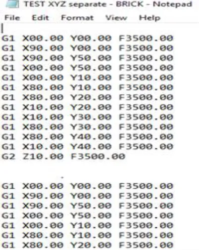
1)Creating the G-Code: G-code language provided to a machine controller that tells the motors where to move, how fast to move, and which path to follow. G-Code instructs X axis of the machine to travel from one point to another points with a specific speed and similarly for Y axis and Z axis[5]. The G-Code of the particular model is writing on the notepad and saved the particular file with an extension .gcode. The file is then loaded to Grbl controller to view the model corresponding to G-Code.
Fig. 2. Creating G-Code
2)Processing the G-Code: User interface was designed using Processing java software. UART communication was chosen for sending G-code file from PC to microcontroller[6]. Bit by bit generated G-Code file is transmitted to ARM. After receiving each bit an acknowledgment signal is given to the PC then only the next bit will be sending otherwise an error signal will indicate.
769
Algorithm -1(a): Algorithm part1
Lines are drawn by CNC printer based on line algorithm. Consider the algorithm part 2 and 3, for the 2D movement consider initial point (x0, y0) and nearest point (x1, y1) in device space. Where x0 and y0 initially set to zero. If dx = x1 – x0 and dy = y1 – y0.
Algorithm -1(b): Algorithm
Extruder will be opened to start extrude on XY plane. If dx>0 and dy>0 the x and y motor rotate in one direction otherwise in opposite direction. If |dx| >|dy| the driving axis is X axis, else if |dy| > |dx| the corresponding driving axis is Y axis. Driving axis is used as the ―axis of control‖ [7]. The particular driving axis is incremented by one unit. At the same time other axis is only incremented when it is needed.
Algorithm -1(c ): Algorithm part3
If G2, make the position of Z axis to its minimum position and then capture the index number of each axis. For the vertical 3D movement consider initial point (z0) and nearest point (z1) in device space. Where z0 initially set to zero. If dz = z2 −z1. The driving axis is incremented by one unit at that moment extruder is closed.
Algorithm -1(d ): Algorithm
770 4.2 Hardware Implementation
Stepper motors are used for 3D movement. This arrangement helps to utilize the entire area. Signals for the motor movement is given by LPC1769. T-Slot aluminum frames are used for the construction of structure. Lead screws were used for linear motion, where the screws are connected to the motor through coupler. Metallic rod has been shaped, which is used to hold the X and Z axis hardware shown in fig 2. The pitch of the lead screw of the X, Y and Z axis is 2mm each. The extruder is mounted on the Z axis which is exactly perpendicular with the XY axis during operation. The extruder is connected in a moving gantry plate. Hardware setup consists of a control unit which is connected to XYZ axis. Three motors are provided for producing the motion in the X, Y and Z axes.
Fig .3. Hardware Implementation
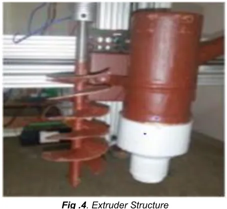
Main element of a 3D concrete printer is an extruder. Where the material is selectively dispensed through a nozzle, this device is called extruder. The 3D extruder is the part of the 3D printer that ejects material in liquid or semiliquid form in order to deposit it in successive layers within the 3D printing volume. In some cases, the extruder serves only to deposit a bonding agent used to solidify a material that is originally in powder form. Here Extruder consist of two elements.
1.Nozzle 2.Rotating element
Fig .4. Extruder Structure
A nozzle is a device designed to control the direction or characteristics of a fluid flow (specially to increase velocity) as it extrudes. Nozzles are used to control the rate of flow, speed, direction. Here Nozzle is used to extrude the concrete mixture from the extruder. Normally nozzle diameter ranging from 1cm to 2cm and the rotating element has a Spiral blade welding on a metal rod and end of this metal rod is connected to NEMA23 stepper motor. Rotating element is used for shaking the concrete mixture during printing time. Purpose of this element is not to set the concrete mixture. After extruding the complete concrete mixture from the extruder, then it will clean up.
5
RESULTS
771
Fig .5. Printing Of 3D Cube
Here shows the final printing of image files. Thus, Gcode given to the printer is of a 3D cube. ARM microcontroller which gives the control signal to XYZ plane and extruder structure. Fig 5 shows the printing of 3D cube.
5
RESULTS
Implemented a 3D concrete printer which fulfill all 3R’s. The printer, which is quick in action, cheaper when compared to conventional approach, ease to operate and economical too. 3D concrete printer presents an inventory revolution in construction fields and highly promising weapon for the future. Even an entire house can be built using 3D concrete printer. The printer can move along all the three direction hence it is capable of printing any type of complex structures. Centrifugal pumping system is used for the concrete extrusion process. The above mention design mix demonstrates to be extrudable, flowable and buildable of an appropriate strength. It can also be used for large buildings construction. This technique can easily be adopted in the case where low cost, flexible and fast building construction method requires.
REFERENCES
[1] Pegna J.‖ Exploratory investigation of solid freeform construction‖, Automation in Construction, 5(5):427– 437, 1997.
[2] Buswell R.A., Soar R., Gibb A.G. and Thorpe A. Freeform construction: ‖mega-scale rapid manufacturing for construction‖, Automation in Construction, 16:224-231, 2007.
[3] Gosselin C., Duballet R., Roux Ph., Gaudillière N., Dirrenberger J. and Morel Ph.‖Large-scale 3D printing of ultra-high-performance concrete – a new processing route for architects and builders.‖Materials and Design, 100:102–109, 2016.
[4] Lim S., Buswell R.A., Le T.T., Austin S.A., Gibb A.G.F and Thorpe T. ―Developments in construction-scale additive manufacturing processes. ―Automation in Construction, 21:262– 268, 2012.
[5] Pritesh Runwal, Anil Shelke, Pankaj Udavant, Sujit Rokade, D.A.Baitule (April 2017), ―Designing and Manufacturing of Mini CNC Plotter‖, International Journal for Research in Applied Science & Engineering Technology (IJRASET), Vol. 5 ,Issue. 4.
[6] K.N.H. Srinivas, Venkata Krishna Pabolu (2010), ‖Design and implementation of a three dimensional
CNC machine‖, International journal on computer science and engineering, Vol. 2, Issue. 8.