Article
1
Weld Magnification Factor Approach in Cruciform
2
Joints Considering Post Welding Cooling Medium
3
and Weld Size
4
Oscar Araque 1,*, Nelson Arzola 2
5
1 Departamento de Ingeniería Mecánica, Facultad de Ingeniería, Universidad de Ibagué, Ibagué 730001,
6
Colombia
7
2 Department of Mechanical and Mechatronics Engineering, National University of Colombia, Bogota,
8
Colombia; narzola@unal.edu.co (N.A.)
9
* Correspondence: oscar.araque@unibague.edu.co; Tel.: +0057-8-2709400
10
Abstract: The objective of this research is to develop an experimental-theoretical analysis about the
11
influence of the cooling medium and the geometry of the welding bead profile in fatigue life and
12
associated parameters with structural integrity of welded joints. A welded joint with cruciform
13
geometry is considered using SMAW, plates in structural steel ASTM A36 HR of 8 mm of
14
thickness and E6013 electrode input. A three-dimensional computational model of the cruciform
15
joint was created using the finite element method. For this model, the surface undulation of the
16
cord and differentiation in the mechanical properties of the fusion zone were considered, the
17
heat-affected zone (HAZ) and base material, respectively. In addition, an initial residual stress
18
field which was established experimentally was considered. The results were a set of analytical
19
expressions for the weld magnification factor Mk. It was found that values for the latter decrease
20
markedly in function of the intensity of the cooling medium used in the post welding cooling
21
phase, mainly due to the effect of the residual compressive stresses. The obtained models of
22
behavior of the weld magnification factor are compared with the results from other researchers
23
with some small differences, mainly due to the inclusion of the cooling effect of the post weld and
24
the variation of the leg of the weld bead. The obtained analytical equations in the present research
25
for Mk can be used in management models of life and structural integrity for this type of welded
26
joint.
27
Keywords: cruciform joint; fatigue; semi-elliptical crack; cooling; weld magnification factor;
28
fracture mechanics
29
30
1. Introduction
31
One of the common failure phenomena in structural engineering materials is fatigue failure. This is
32
associated with certain flaws in the material or any geometric detail which, after a certain number
33
of load cycles, generate the initial discontinuity. Either through manufacturing or created by
34
situations of use, pre-existing flaws create the critical conditions from which the material breakage
35
is developed. Fracture mechanics’ purpose is to analyze and determine the mechanical behavior of
36
structural elements, considering the existence of flaws in the material to define the conditions or
37
criteria of breakage [1].
38
The first theory that explains the fracture of cracked solids, known as elastic linear mechanics
39
fracture (LEFM), was initially proposed by Griffith at the beginning of the last century (Griffith,
40
1920), and subsequently developed by Irwin, in the second half of the same (Irwin, 1957). Up to its
41
appearance, only the failure by plastic collapse, where the material deforms plastically without any
42
fracture, had well-structured physical and mathematical foundations. The LEFM came to fill the
43
gap that existed in the opposite situation of the plastic collapse, when the fracture occurs in
44
conditions of small deformation and in stress levels much lower than those that lead to the start of
45
the material plastic deformation processes [2].
46
Using the principles of the MFEL, it is possible to assess the stable propagation of fatigue cracks in
47
welded joints when using the empirical relationship proposed by Paris and Erdogan [3,4].
48
= C(∆K) = C β∆σ√πa (1)
49
To: ∆K ≤ ∆K ≤ K (2)
50
51
where the C and m parameters are constant of the material for a range of stress stress ∆σ and R
52
(load rate) fixed; ∆K is the range of the stress intensity factor; β is a dimensionless function that
53
depends on the geometry of the component and the crack size (a); ∆K is the range of the stress
54
intensity factor threshold; and finally, ∆K is the fracture toughness of the material for the
55
condition of flat deformation.
56
When the stress intensity factor reaches a critical value, and the ASTM E399 [5] and ASTM D5045
57
[6] requirements are met, the critical value can be regarded as a material property called fracture
58
toughness for flat deformation, KIC. For that value, crack starts its unstable spread, fracturing the
59
component into two parts. In this way, the local fracture approach on Mode I is determined, on the
60
basis of the following expression [7].
61
βσ √πa → K (3)
62
In welded joints, the stress fields in front of the crack are more complex to determine due to the
63
microstructural changes that occur as a result of the thermal cycle of the cooling system [8]. The
64
crack tip in a weld can be described as a semi-elliptical curve with depth (a) and length (2c). In
65
general, using Mode I, the stress intensity factor is given by [9].
66
= √ (4)
67
68
Where σ is the applied stress, and Y is a correction factor dependent on the load and the geometry
69
of the crack size. The Y parameter is influenced by a number of factors that can be represented as
70
follows:
71
Y = ∅ (5)
72
73
Mk is a factor which considers the presence of the weld; MS is a correction factor of the free surface
74
area near the crack tip; Mt is a correction factor of the free surface in the crack tip; and finally, φ0
75
complete is the integral of the ellipse. The latter can be expressed as:
76
77
∅ = / 1 − 1 − sen ∅ / d∅ (6)
79
Where φ is defined as the angle of an ellipse. The values of MS and Mt depend on the joint
80
geometry, and not evaluating them can lead to an error that is normally about 0.13%. This is
81
because the stress field is low-intensity when the distance is greater from the weld of toe; therefore,
82
it can be avoided [10].
83
84
A number of researchers have determined expressions for the calculation of Mk, such as Lie and
85
Zhao [11], and Maddox and Andrews [12], who made a review of the British Standards PD6493 and
86
BS7608, for the steel structures cruciform design subjected to fatigue, establishing a value of Mk
87
between 0.83 and 1.00 for cracks located at the weld of toe. The Hobbacher researcher [13], found an
88
expression for Mk, for the case of a cruciform welded joint and 0.02 mm-sized crack, finding that
89
the effect of the weld of toe produces a variation of 5% for various relationships of assessed aspects.
90
The obtained equation by Hobbacher is described below:
91
92
M = C para M ≥ 1 (7)
93
94
The magnitudes of C and k are dependent on the aspect and the geometry of the joint. Maddox [12]
95
presented a dimensionless factor M which allows estimation of the influence of stresses generated
96
by the geometric profile of the welded joints on the stress intensity factor.
97
=
√ (8)
98
The researcher [9, 14] carries out a comparative analysis between the estimated models by Maddox,
99
Andrews and Hobbacher for the determination of the weld magnification factor Mk. In this work, it
100
is determined that the crack depth is a parameter that affects between 15% to 65% of the parametric
101
equation for the calculation of Mk. Concomitant researcher Brennan [15] developed a comparative
102
parametric equation for the determination of the weld magnification factor, in a cruciform welded
103
joint. In addition, the results were compared with those previously developed by the researchers
104
[10, 16, 17], establishing a good level of correspondence between the magnitudes encountered and
105
the previous research. In the case of welded joints in test tubes with cruciform geometry, Zhao and
106
Lie [11] include a set of equations for estimating the effect of misalignment on different types of
107
welded joints with a semi-elliptical surface crack. The Takeshi study [18] shows that failures start at
108
the root of the weld being the stress hub that defense the propagation of the crack and its life.
109
110
The study using numerical methods of the transient thermal behavior of the welding process goes
111
back to the 1980s, highlighting the work done by Friedman [19]. Among the numerical methods
112
used to carry out the study of transitional period thermal behavior, the finite element method is one
113
of the most popular. This technique has gained special importance mainly when it includes a mesh
114
refinement around the tip of the crack, besides the effect crack of the thermal cycle in the stress
115
intensity factors KI assessment and the weld magnification factor Mk. Although conceptually the
116
factors are obtained in a direct way, finite element analysis, with conventional elements near the
117
smaller elements, size 1/√r, some researchers [20,21] introduced a direct method, by moving the
119
composed node of 8-noded quadrilateral elements up to a quarter of the node in the crack tip and
120
relocating the nodes of the mid-point to a fourth at the end of the crack. In the case of linear elastic
121
deformation, the elements Plane2 (2-D, 6-noded triangle), Plane82 (2-D, 8-noded quadrilateral), and
122
Solid95 (3-D, 20-noded brick), are used in ANSYS to stabilize the residual stress field by moving the
123
nodes to a fourth of the tip of the crack. Once the field of stress is established the parameters of
124
fracture are obtained [22]. Certain configurations of elements and nodes produce unique
125
displacements. While this type of behavior is undesirable for the majority of the analyzes, it is ideal
126
for elasticity problems in cracks. By forcing elements in the crack tip to have a unique deformation,
127
1/√x can improve the accuracy and reduce the need for a high degree of refinement of mesh in the
128
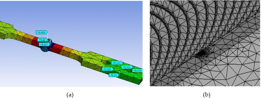
crack tip. This singular deformation is only applied in the crack tip.
129
130
Some contributions of this research is the three-dimensional computational modeling of a welded
131
joint, using the finite element method, where the surface ripple on the surface of the weld bead and
132
differentiation in the mechanical properties of the fusion zone, the heat-affected zone (HAZ) and
133
base material, respectively. In addition, the use of an initial residual stress field for the welded joint
134
and adjacent region that emulated was determined by the experimental path. The fundamentals of
135
Fracture Mechanics were employed in the numerical modeling of the welded joint with the
136
presence of a surface crack semi-elliptical type discontinuity at the weld toe. The latter is defined as
137
a semi-elliptical surface crack with a small aspect. Because of this study, a set of mathematical
138
models for the weld magnification factor were obtained for cruciform welded joints, which can be
139
used in the prediction of the fatigue life of this type of welded joint.
140
141
2. Materials and methods
142
For the definition of the experimental and analytical procedures, previous studies were used as
143
reference in cruciform test tubes subjected to biaxial cycles of stress to analyze fatigue. In these
144
studies, the thicknesses, welding dimensions, and size and penetration depth of the weld were
145
observed. For the experimental development of the present work, a carbon steel ASTM A36 HR
146
Commercial 8 mm thickness and material of the electrode E6013 were used. The Shielded Metal
147
ArcWelding (SMAW) process is a simple, low cost and suitable way of joining most metals and
148
alloys commonly used in industry [23]. The electrical characteristics of the process (SMAW) used in
149
the joint are shown in Table 1, for each weld size (leg).
150
151
152
Table 1. Main characteristics of the welding procedures used.
153
154
Weld size (leg) Diameter of
the electrode
E-6013
Electrical parameters Forward
Speed
155
For the purpose of generating a pilot input to the computational runs and comparison of the
156
residual stress from the thermal cycle [24], the measurement of the temperature of the test piece
157
during the post welding cooling for the two means of cooling (air and water) using two
158
thermocouples type K, were located laterally on each edge of the bead welded. The thermocouples
159
were connected to a data acquisition card or-9211, mounted on the NI CDAQ-9172, and then to the
160
PC. The layout of the thermocouples in the measuring cylinder is shown in Figure 1. LabView
161
Signal Express 2011 software was used to acquire and process data from the thermocouples and
162
obtain the cooling curves.
163
164
165
Figure 1. Connection of the thermocouples.
166
167
For the process of plate-cutting, the technique of high-density plasma was used. Due to the cutting
168
technique used, the heat affected zone (HAZ), with a thickness of 8 mm, reached a millimeter of
169
depth of the surface that results from the cut. After this preliminary cut, the central area of the test
170
piece went into a mechanical process through milling to remove the endings of the weld bead,
171
prone to higher density of defects product at the beginning and breakdown of the electric arc. The
172
geometry of the fixture to be used in the tests after final machining is presented in Figure 2.
173
174
175
Figure 2. Geometric fixture test (mm scale).
176
The variables used for the manufacture of the test specimens are indicated below in Table 2.
178
179
Table 2. Variables for manufacturing
180
181
weld size (leg)
C Cooling means
3 mm Air calm
5 mm Agua
182
Fatigue tests were performed by axial load on cruciform geometry specimens, for different load
183
ratios (R), defined as:
184
R=Pmin/Pmax, where; Pmin: Minimum load and Pmax: Maximum load
185
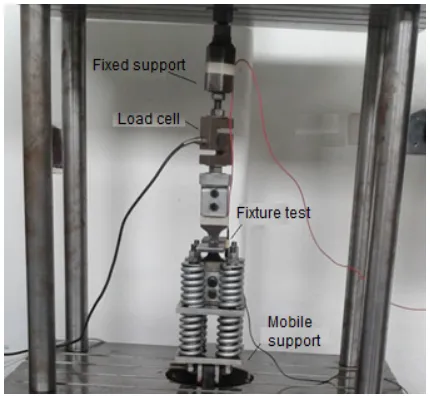
The assembly made for the test is shown in Figure 3.
186
187
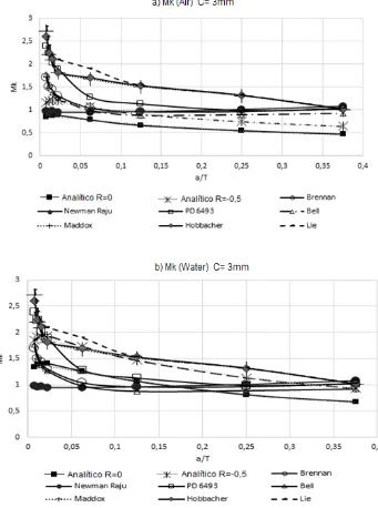
188
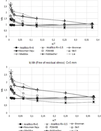
189
Figure 3. Assembly for the axial fatigue test
190
191
The operating parameters of the equipment used are indicated in Table 3.
192
193
Table 3. Parameters of the equipment.
194
195
Parameters Magnitude Unit
Maximum load 900 kgf
Frequency of operation 12 Hz
Engine power 3 hp
Nominal Motor Amperage 8,6 A
Supply voltage 206 (v)
Amperage at the Operation point 8,3 A
Load application cycles per Hour 8200 cycles
Diameter Pulley Driven [in] 12 in
Transmission Ratio 0,5
Motor Speed rpm @ 60Hz 3445 rpm
196
To begin the simulations by the finite element method, the software ANSYS was used. The
197
determination of stress intensity factors for geometries and application modes of simple loads can
198
be carried out through easily implemented analytical solutions. But when the geometries and loads
199
are more complicated, these induce complex stress and strain fields on the structural component;
200
therefore, it is recommended to use the Finite Element Method to determine said factors [25]. Also,
201
the displacement correlation technique (DCT) is relatively simple to perform and offers sufficiently
202
precise solutions for the purpose of this work. Thus, the DCT method is employed in the modeling
203
of the cracks in the weld joint analyzed.
204
205
To describe the stress field intensity in the region near to the crack vertex, it is necessary to use
206
singular elements, with an additional node at a distance of a quarter of the size of the fissure vertex.
207
With these singular elements, the stress intensity factors can be calculated in the following way.
208
209
K = ∙ ∙ 4(v − v ) + (v − v ) (9)
210
K = ∙ ∙ 4(u − u ) + (u − u ) (10)
211
212
With: μ = ( ) k = 3 − 4ν (plane strain) (plane stress) (11)
213
Where:
214
KI, KII: Stress intensity factors for load modes I and II, respectively (MPa √m).
215
E: Elasticity modulus of the material (MPa).
216
ν: Poisson’s ratio of the material.
217
L: Characteristic length of the singular element (mm).
218
(ui; vi): Displacements of the nodes of the singular elements (mm).
219
220
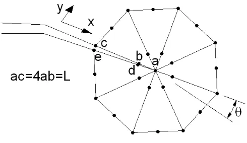
The Figure 4 shows the singular elements, the disposition of the nodes and the displacements
221
employed in calculating the stress intensity factors.
222
224
225
Figure 4. Disposition of control nodes on the crack vertex
226
227
The tip of the crack must be meshed with small singular concentric elements and should not vary in
228
size as the crack extends. The rest of the component is meshed with quadrangular elements that
229
provide good precision.
230
231
Various methods are available to establish the orientation of the crack as it extends, although all
232
basically lead to similar results. This work uses the strain energy density method on the crack
233
vertex (ψ), which is expressed according to (12). The relative local minimum of ψ corresponds to a
234
large volume change and is identified with the region dominated by macro dilatation leading to
235
crack growth. Accordingly, this method establishes that the crack propagates in the direction of
236
minimum strain energy released [26].
237
238
ψ = A K + 2A K K + A K (12)
239
Where:
240
Aij: Coefficients that depend on the material’s elastic properties.
241
242
A 3D computer model of the cruciform test tubes for each of the two legs of welding considered
243
included the temperature profiles obtained experimentally and the determination of the profile of
244
stress for the residual cooling conditions in calm air and water, as shown in Figure 5 (a). At a later
245
stage in the modeling, surface semi-elliptical, a crack was included at the weld toe, as shown in
246
Figure 5 (b). The interest in this second model focused on studying the stress-strain field near the
247
front of the semi-elliptical crack under various conditions of cyclic loading (changing the load ratio
248
R). Crack sizes used in this work for the computer simulations are shown in Table 4, naming c, the
249
size of the semi-major axis, and a, the dimension of the semi-minor axis of the semielliptical crack.
250
(a) (b)
Figure 5. (a) The temperature profile for the cooling cycle post welding and residual stress, (b)
252
semi-elliptical crack on welding and plain generated for the finite element model.
253
254
Table 4. Crack sizes of semielliptical section.
255
256
Semi-major axis (c)
(mm)
Semi-minor axis (a)
(mm)
0.15 0.06 0.23 0.09 0.30 0.12 0.45 0.18 1.25 0.50 2.50 1.00 5.00 2.00 7.50 3.00
257
With the FEM model implemented, the values of the weld magnification factor are determined for
258
crack sizes that appear in Table 2. The weld magnification factor is calculated by:
259
260
M = ( )
√ (13)
261
Where:
262
K ( ): Stress intensity factor obtained by FEM (MPa √m).
263
σ : Nominal stress (MPa).
264
265
The magnitudes of the nominal and alternant stress of operation appear in Table 3. It is calculated
266
using the following equation:
267
σ = (14)
268
Being:
269
F: Load operation (N).
270
L: Length of the weld bead (mm).
272
σ = (15)
273
Being:
274
C: weld size leg (mm).
275
276
The values of the nominal and alternant stresses of the axial fatigue test are shown in table 5.
277
278
Table 5. Nominal and alternant stresses for the fatigue test.
279
280
Load rate
(R=Pmin/Pmax)
Nominal stress
(MPa)
Alternant stress
(MPa) C=3 mm
Alternant stress
(MPa) C=5 mm
0 55.2 71.3 100.9 -0.5 36.8 35.5 64.6
281
3.
Discussion and Results282
As a product of computational modeling, the residual stress profile was obtained for each of the
283
legs of welding and cooling means analyzed. In Figure 6, the residual stress profile is shown for a
284
vessel with a leg of five millimeters, where the zero position indicates the location of the weld of
285
toe. It is found that the modeled residual compressive stresses were compressive typed and its
286
magnitude is directly related to the intensity of the cooling medium and the size of the bead. The
287
mean of cooling water turned out to be the most intense, introducing a rate of cooling in the initial
288
range analyzed of -112 °C/s and a residual stress at the weld of toe for a leg of 5 mm equal to -119
289
MPa. On the other hand, it was found that large legs induce higher residual stresses, prompted by
290
the need for a greater heat input to the board and to the greater three-dimensional restriction to
291
thermal contraction.
292
293
Figure 6. Residual stress obtained from the theoretical model MEF for a leg of 5 mm.
294
-140.000 -120.000 -100.000 -80.000 -60.000 -40.000 -20.000 0.000
0 11 22
Residual stress
(MPa)
295
Using the axial fatigue machine, the stress - life tests were carried out for the specimens under
296
study. The experimental results for the different means of cooling and welding legs are shown
297
below, in Figure 7 (a). It is observed that more severe cooling means reduce life to fatigue. In
298
Figure 7 (b) it is observed that the size of the leg did not affect the life of the specimens
299
considerably. In Figure 7 (c), it is observed that the more tensile load ratios minimize the life of the
300
specimens.
301
302
303
304
0 20 40 60 80 100 120
0.00E+00 2.00E+05 4.00E+05 6.00E+05 8.00E+05 1.00E+06 1.20E+06
Alternant
stress
(MPa)
Load Cycles (N)
Water • Air ♦
a. Diagram S - N
0 20 40 60 80 100 120
0.00E+00 2.00E+05 4.00E+05 6.00E+05 8.00E+05 1.00E+06 1.20E+06
Alternant
stress
(MPa)
Load Cycles (N)
C= 3mm • C= 5mm ♦
305
Figure 7. Diagrams Stress – Number of Cycles
306
307
The behavior of the weld magnification factor Mk in the presence of residual stresses was evaluated
308
analytically. Weld magnification factors Mk obtained with the presence of a residual stress field has
309
been appointed in the present research. This allows a distinction on this factor in the sense that it
310
involves the effect of the residual stress field in the calculation of the stress intensity factor. The
311
expression (9) is used in the calculation of Mk in function of the dimensionless crack depth (a/T)
312
and the possible combinations between weld size (leg) and the cooling medium used.
313
314
In the Table 6 the values obtained for Mk are shown for the different relationships of load rate, type
315
of cooling, and weld size of the object of study. The behavior of the modified Mk factors, in function
316
of the dimensionless size of crack, is shown in Figure 8 for the two sizes of legs analyzed.
317
318
Table 6. Modified weld magnification factor Mk to crack at the weld toe:
319
(a) weld size (leg) of 3 mm and (b) weld size (leg) of 5 mm.
320
321
a) Modified weld magnification factor Mk for weld size (leg) of 3 mm.
322
Load
rate (R) a/T
Cooling
air
Cooling
water
Free of
residual stress
0 0.008 0.848 1.345 1.449
0.011 0.884 1.389 1.384
0.015 0.878 1.399 1.404
0.023 0.884 1.408 1.357
0.063 0.783 1.260 1.077
0.125 0.662 1.067 0.853
0.250 0.547 0.811 0.746
0 20 40 60 80 100 120
0.00E+00 2.00E+05 4.00E+05 6.00E+05 8.00E+05 1.00E+06 1.20E+06
Alternant
stress (MPa)
Load Cycles (N)
R=0 • R= -0,5 ♦
0.375 0.472 0.676 0.758
-0.5 0.008 1.159 1.851 1.428
0.011 1.206 1.911 1.384
0.015 1.199 1.925 1.404
0.023 1.207 1.937 1.357
0.063 1.069 1.733 1.077
0.125 0.904 1.469 0.854
0.250 0.746 1.135 0.746
0.375 0.644 0.930 0.750
323
324
b) Modified weld magnification factor Mk for weld size (leg) of 5 mm.
Load
rate (R) a/T
Cooling
air
Cooling
water
Free of
residual stress
0 0.008 0.551 0.333 1.575
0.011 0.534 0.359 1.531
0.015 0.522 0.352 1.471
0.023 0.522 0.378 1.307
0.063 0.454 0.393 0.969
0.125 0.440 0.422 0.803
0.250 0.398 0.422 0.668
0.375 0.373 0.413 0.717
-0.5 0.008 0.719 0.455 1.575
0.011 0.697 0.491 1.538
0.015 0.681 0.494 1.472
0.023 0.682 0.529 1.307
0.063 0.593 0.536 0.969
0.125 0.574 0.576 0.804
0.250 0.520 0.576 0.674
0.375 0.509 0.564 0.717
332
a) Modified weld magnification factor Mk for weld size (leg) of 3 mm.
333
334
335
b) Modified weld magnification factor Mk for weld size (leg) of 5 mm.
336
337
Figure 8. Modified weld magnification factor Mk to crack at the weld of toe: (a) weld size (leg) of 3
338
mm and (b) weld size (leg) of 5 mm.
339
340
0 0.5 1 1.5 2 2.5 0. 00 75 0. 01 125 0. 01 5 0. 02 25 0. 06 25 0. 12 5 0. 25 0. 37 5 0. 00 75 0. 01 125 0. 01 5 0. 02 25 0. 06 25 0. 12 5 0. 25 0. 37 5 MkR=0 R=-0,5 Relación a/T 0 0.2 0.4 0.6 0.8 1 1.2 1.4 1.6 1.8 0. 00 75 0. 01 125 0. 01 5 0. 02 25 0. 06 25 0. 12 5 0. 25 0. 37 5 0. 00 75 0. 01 125 0. 01 5 0. 02 25 0. 06 25 0. 12 5 0. 25 0. 37 5 Mk
The theoretical obtained results in the present work for the modified weld magnification factor
341
Mk, for condition of free stresses, were compared with the results achieved by other researchers
342
[9-13, 15-17]. In Figure 9, the results for the weld magnification factor are shown, for the case of a
343
crack at the weld of toe and without residual stress, and verifies the correspondence of the
344
developed numerical model with the results obtained by other researchers. The analytical results
345
obtained involve several weld sizes and load rates.
346
347
348
349
Figure 9. Weld magnification factor Mk without residual stress vs. results of other researchers: (a)
350
weld size of 3 mm and (b) weld size of 5 mm.
351
352
In Figures 9 (a) and (b) it can be noted that the weld magnification factor Mk is independent from
353
information in Table 6 for the modified weld magnification factor Mk, including the effect of the
355
residual stress reached by the air and water cooling medium, it is possible to make a comparison
356
with the results obtained by other researchers. This comparison of results is shown in Figures 10
357
and 11. The observed trend with the modified weld magnification factor is to markedly diminish in
358
function of the post weld cooling medium intensity, for the range of relative size of crack a/T<0.1.
359
This behavior is related to the coupled benefits of the residual compressive stresses that arise
360
during the post-welding cooling for the region where the modeled crack occurs in the present work.
361
362
363
Figure 10. Modified weld magnification factor Mk with the presence of residual stress vs. other
364
researchers: (a) air and weld size of 3 mm and (b) water and weld size of 3 mm.
365
367
368
Figure 11. Modified weld magnification factor Mk with the presence of residual stress vs other
369
researchers: (a) air and weld size of 5 mm and (b) water and weld size of 5 mm.
370
371
With the results obtained for the weld magnification factor, a regression analysis is carried out to
372
obtain analytical equations that relate to the dimensionless size of the crack. Table 7 shows the
373
expressions of Mk(a/T) for the free condition of residual stresses. In Table 8, the expressions of Mk(a/T)
374
are shown for the condition of post-weld cooling in calm air. Finally, Table 9 shows the expressions
375
of Mk(a/T) for the condition of post-weld cooling in water (in the equations Ω=a/T). These analytical
376
expressions are particularly useful to establish models for the prediction of fatigue crack
377
propagation and the design of a life management program for welded structures of the studied
378
type.
379
380
0 0.5 1 1.5 2 2.5 3
0 0.05 0.1 0.15 0.2 0.25 0.3 0.35 0.4
Mk
a/T a) Mk (Air) C= 5mm
Analitico R=0 Analitico R=0,5 Brennan
Newman Raju PD6493 Bell
Maddox Hobbacher Lie
0 0.5 1 1.5 2 2.5 3
0 0.05 0.1 0.15 0.2 0.25 0.3 0.35 0.4
Mk
a/T
b) Mk (water) C= 5mm
Analitico R=0 Analitico R=0,5 Brennan
Newman Raju PD 6493 Bell
381
Table 7. Adjusted expressions for the weld magnification factor for the free condition of residual
382
stresses.
383
Weld size (leg)
3 mm 5 mm
Mk = 0,0077Ω3 - 0,1121Ω2 + 0,351Ω + 1,1592
Mk = 0,0101Ω3 - 0,1361Ω2 + 0,3671Ω + 1,3123
Valid for: 0.02 ≤Ω≤ 0.33.
384
Table 8. Adjusted expressions for the modified weld magnification factor Mk for the condition of
385
post weld cooling in calm air.
386
387
Load rate (R)
Weld size
3 mm 5 mm
0 Mk = 2.5098Ω2 – 2.0772Ω + 0.9002 Mk = 1.5822Ω2 – 1.0261Ω + 0.5416
-0.5 Mk = 4.5708Ω2 – 3.7817Ω + 1.6383 Mk = 3.2069Ω2 – 1.8877Ω + 0.9443
388
Table 9. Adjusted expressions for the modified weld magnification factor Mk for the condition of
389
post weld cooling in water.
390
Load rate (R)
Weld size
3 mm 5 mm
0 Mk = 3.2442Ω2 – 3.2442Ω + 1.4311 Mk = 7.0363Ω3 – 5.4379Ω2 + 1.2513Ω + 0.338
-0.5 Mk = 5.5871Ω2 – 5.7921Ω + 2.6206 Mk = -117.47Ω4 + 97.992Ω3 – 28.427Ω2 + 3.4545Ω + 0.6097
391
4. Conclusions
392
We conducted a theoretical experimental study about the behavior of fatigue in welded joints with
393
cruciform geometry. A 3D computer model of the welded joint was used throughout the finite
394
element method where several features were introduced, such as the superficial natural undulation
395
of the weld bead and established a distinction between the mechanical properties of the fusion
396
zone, the heat affected zone and the base material, respectively. In addition, a residual stress field
397
was introduced for the welded joint and the surrounding region, which emulates set one by
398
experimental manner. In the computational simulation of the superficial semi-elliptical crack at the
399
weld of toe, a convergence of the model for 405 428 nodes, with a computational cost in CPU time
400
of 2680 s for each iteration, was reached.
401
It was determined that the residual stresses are of compression higher for the more intense cooling
403
medium (water). In addition, it can be noted that larger weld size induces greater residual stresses,
404
prompted by the need for a greater heat input to the joints and to the greater three-dimensional
405
restriction to a thermal contraction of the weld joint. Fatigue tests indicate that more severe cooling
406
means minimizing the life of the welding specimens in the same way as the more tensile load ratios.
407
It is observed that the specimens failed mainly in the weld toe.
408
409
A unique finding of the present work is the reaching of analytical expressions obtained by the weld
410
magnification factor Mk for two sizes of the weld and two post welding cooling media. The
411
analytical equations obtained consider the residual stresses induced by these two post welding
412
cooling mediums. The analytical expressions for Mk in the present research have good
413
correspondence with the obtained results by other authors, in the case of welded joints without
414
residual stresses. These expressions can improve the calculation codes, testing standards and the
415
structural integrity of welded joints verification. It can be noted that the observed trend with the
416
modified weld magnification factor is to markedly diminish, in function of the intensity of post
417
welding cooling medium for a dimensionless crack size below a/T<0.1. This behavior is related to
418
the coupled benefits of the residual compressive stresses that arise during the post-welding cooling
419
for the assessment region of the type of crack studied.
420
421
Acknowledgments: The authors would like to thank at the research direction of the Universidad de Ibagué
422
project number 15-364-INT and the Universidad Nacional de Colombia .
423
Author Contributions: In this work Oscar Araque and Nelson Arzola conceived and designed the experiments
424
and analyzed the results obtained.
425
Conflicts of Interest: The authors declare no conflict of interest.
426
References
427
[1] Cicero Gonzalez, S., Evaluación de la integridad estructural de componentes sometidos a
428
condiciones de bajo confinamiento, Tesis doctoral, Universidad de Cantabria, Santander. 2007.
429
[2] Flores Le Roux, R. M., Estudio de la propagación de grietas en Materiales dúctiles, Tesis
430
doctoral, Universidad Politécnica de Madrid. 2002; Madrid.
431
[3] Anderson, T.L., Fracture Mechanics, Fundamentals and Applications. 2000, 2nd Edition, CRC
432
Press.
433
[4] Paris, P.C., Erdogan, F, A., Critical analysis of crack propagation laws, J. Basic Eng. 1961, vol. 85,
434
pp. 528– 534.
435
[5] ASTM E399. Standard Test Method for Linear-Elastic Plane-Strain Fracture Toughness KIc of
436
Metallic Materials, Active Standard ASTM E399, 2008.
437
[6] ASTM D5045. Standard Test Methods for Plane-Strain Fracture Toughness and Strain Energy
438
Release Rate of Plastic Materials, Active Standard ASTM D5045, 1999.
439
[7] Hernandez, H., Espejo, E., Mecánica de fractura y análisis de falla, Colección Universidad
440
Nacional de Colombia, Bogotá. 2002
441
[8] Guo, J., Zhou, Y., Liu, C., Wu, Q., Chen, X., & Lu, J. Wire arc additive manufacturing of AZ31
442
magnesium alloy: Grain refinement by adjusting pulse frequency. Materials. J. 2016, 9(10), 823.
443
[9] Lie ST, Zhao HS, Vipin SP. New weld toe magnification factors for semi-elliptical cracks in
444
[10] Raju, I.S., Newman, J.C., Stress-intensity factors for a wide range of semi-elliptical surface
446
cracks in nite-thickness plates’’, Engng Fracture Mech. 1979, vol. 11:8, pp. 17-29.
447
[11] Zhao H.S, Lie S.T. Determination of dimensionless stress intensity factor of plate-to-plate butt
448
welds between axially aligned members of different thickness. Engineering Fracture Mechanics.
449
2017, 172; 90–105.
450
[12] Maddox, S.J., Applying Fitness-for Purpose Concepts to the Fatigue Assessment of Welded
451
Joints, The International Conference on Fatigue, Toronto, Ontario Canada. 1994, 72-81.
452
[13] Hobbacher, A. Stress intensity factors of welded joints. Engineering fracture mechanics. 1993,
453
46(2), 173-182.
454
[14] Bowness D, Lee MMK. Prediction of weld toe magnification factors for semi-elliptical cracks in
455
T-butt joints. Int J Fatigue 2000, 22:369–87
456
[15] Brennan, F.P., Dover, W.D., Kare, R.F., Hellier, A.K. Parametric equations for T-butt weld
457
toe stress intensity factors, International Journal of Fatigue, 1999, vol. 21, pp. 1051–1062.
458
[16] Frise, P. R., & Bell, R. Fatigue crack growth and coalescence at notches. International journal of
459
fatigue,1992, 14(1), 51-56.
460
[17] Standard, B. (1991). PD6493. Guidance on methods for assessing the acceptability level of flaws
461
in fusion welded structures (1991) Published Document, 2nd edn. Welding Standards Poilicy
462
Committee, Technical Committee WEE/37 (Draft for Approval 90/7813). London: British Standards
463
Institution.
464
[18] Takeshi, M., Evaluation Formula for Fatigue Strength of Cruciform Welded Joints Failing
465
from Weld Roots under Bi-Axial Loading, Department of Civil and Environmental
466
Engineering, Hosei University, Kajino-cho, Koganei-shi, Tokyo. 1984, 184-185.
467
[19] Friedman, E., Finite Element Analysis of Arc Welding. Report WAPD-TM-1438. Department
468
of Energy, USA. 1980, 1-7.
469
[20] Henshell, R.D., Shaw, K.G., Crack Tip Finite Elements are Unnecessary, International Journal
470
for Numerical Methods in Engineering. 1975, vol. 9, pp. 495–507.
471
[21] Barsoum, R. S. Triangular quarter-point elements as elastic and perfectly-plastic crack tip
472
elements. International Journal for numerical Methods in engineering. 1977, 11(1), 85-98.
473
[22] Erdogan, M., Ibrahim, G., The finite element method and applications in engineering using
474
ANSYS, Springer. 2006
475
[23] Naves, J.A.; Carvalho, G.; Rodrigues, A.; Fernandes, M.S.; Santos, F.; Medeiros, G. Discontinuity
476
Detection in the Shield Metal Arc Welding Process. Sensors. J. 2017, 17, 1082; doi:10.3390/s17051082
477
[24] Araque de los Ríos, Oscar Javier, & Arzola de la Peña, Nelson. Estudio teórico experimental
478
sobre el fenómeno de enfriamiento postsoldadura en una unión soldada cruciforme. Ingeniare.
479
Revista chilena de ingeniería. 2016, 24(2), 228-238.
480
https://dx.doi.org/10.4067/S0718-33052016000200006
481
[25] Tada, H. Paris, P.C. and Irwin, G.R. The stress analysis of cracks handbook, St. Louis (MO):
482
Del Research Corporation, 1973, 452-620.
483
[26] Lie, S.T., Zhao, Z., Yan, S.H., Two-dimensional and three-dimensional magnication factors, Mk,
484
for non-load-carrying fillet welds cruciform joint, Engineering Fracture Mechanics. 2000, vol. 65, pp.
485
435-453.
486